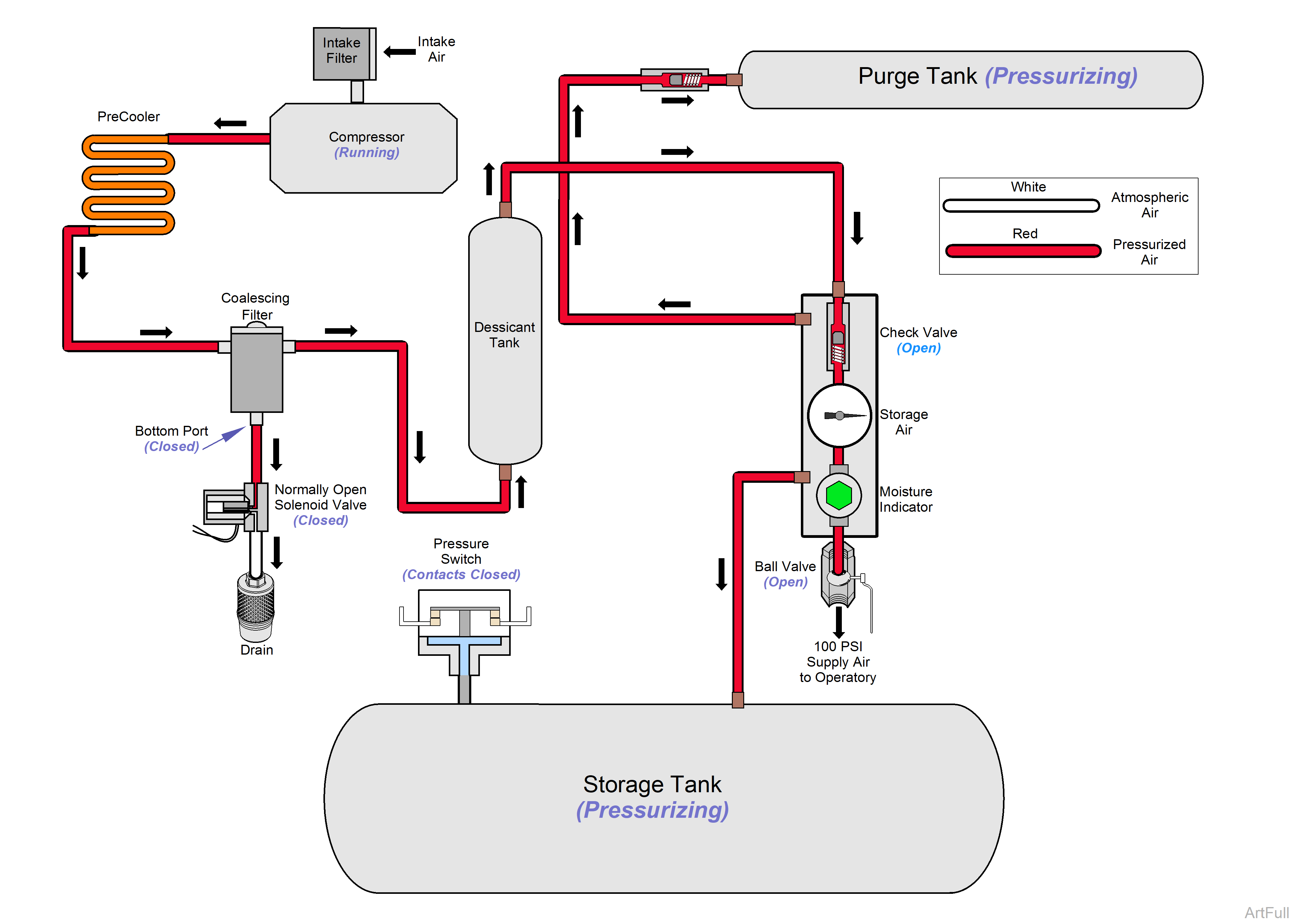
PowerAir Compression Cycle Theory of Operation
Atmospheric air is drawn in through intake filters to the compressor head(s) where air is compressed and exhausted. Air travels through the pre-cooler where it is cooled 10 to 15° F (-12.2 to -9.4 Celsius) within ambient room temperature. Cool air enters the coalescent filter, which removes 99.9997% of all particulate matter.
As the clean air travels through the desiccant tank it is dried to -25°F (-31.7 Celsius) dew point. The clean dry air flows into the main storage tank through a check valve. Some air is directed to the purge tank. As both tanks fill, the pressure switch opens at 100 PSI Max +/- 5 PSI and stops the compressor.
Room temperature should be between 40° and 100°F (4°C to 38°C). Lack of proper ventilation is the main reason for premature compressors failures. Whenever possible, use exhaust fan to bring cool air from dental office to the equipment room, or run fresh air intake lines to the outside so the compressor can breathe in fresh, outside air. Exhaust the stale, hot air out through the roof or side wall.
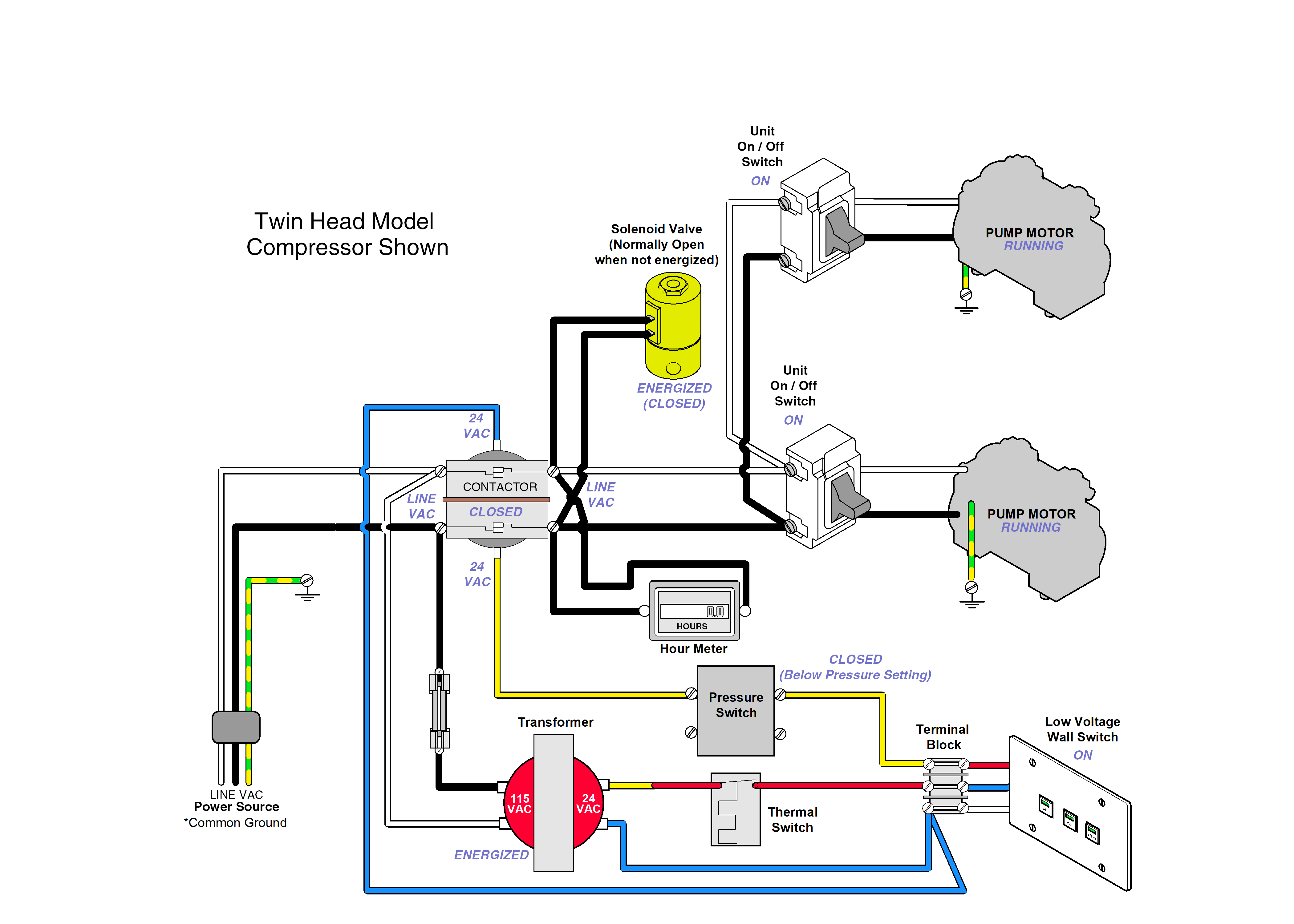
Early units routed 24v from the transformer through the low voltage wall switch and pressure switch contacts to energize the contactor.
•Line voltage from the power source is always present on one side of the contactor contacts.
•Line voltage is also being supplied to the 24 VAC transformer energizing it.
•The transformer supplies 24 VAC to the low voltage wall switch and to one side of the 24 VAC contactor coil. When the low voltage wall switch is in the on position and the pressure switch is closed, the contactor coil is energized closing the contacts.
•With the contacts closed, line voltage is supplied to one side on the unit on/off switches.
•When the unit on/off switches are turned on, line voltage is supplied to the motors.
•The pressure switch will regulate tank pressure by closing it's contacts when the tank pressure drops to 80 PSI + / - 5 PSI or below and will open the contacts when tank pressure reaches 100 PSI max. + / - 5 PSI shutting off compressor.
• Line voltage is also supplied to the normally open solenoid valve closing the valve when the compressor is running preventing compressed air from being discharged through the solenoid valve. When the compressor is not running the solenoid valve is open allowing the compressor to purge.
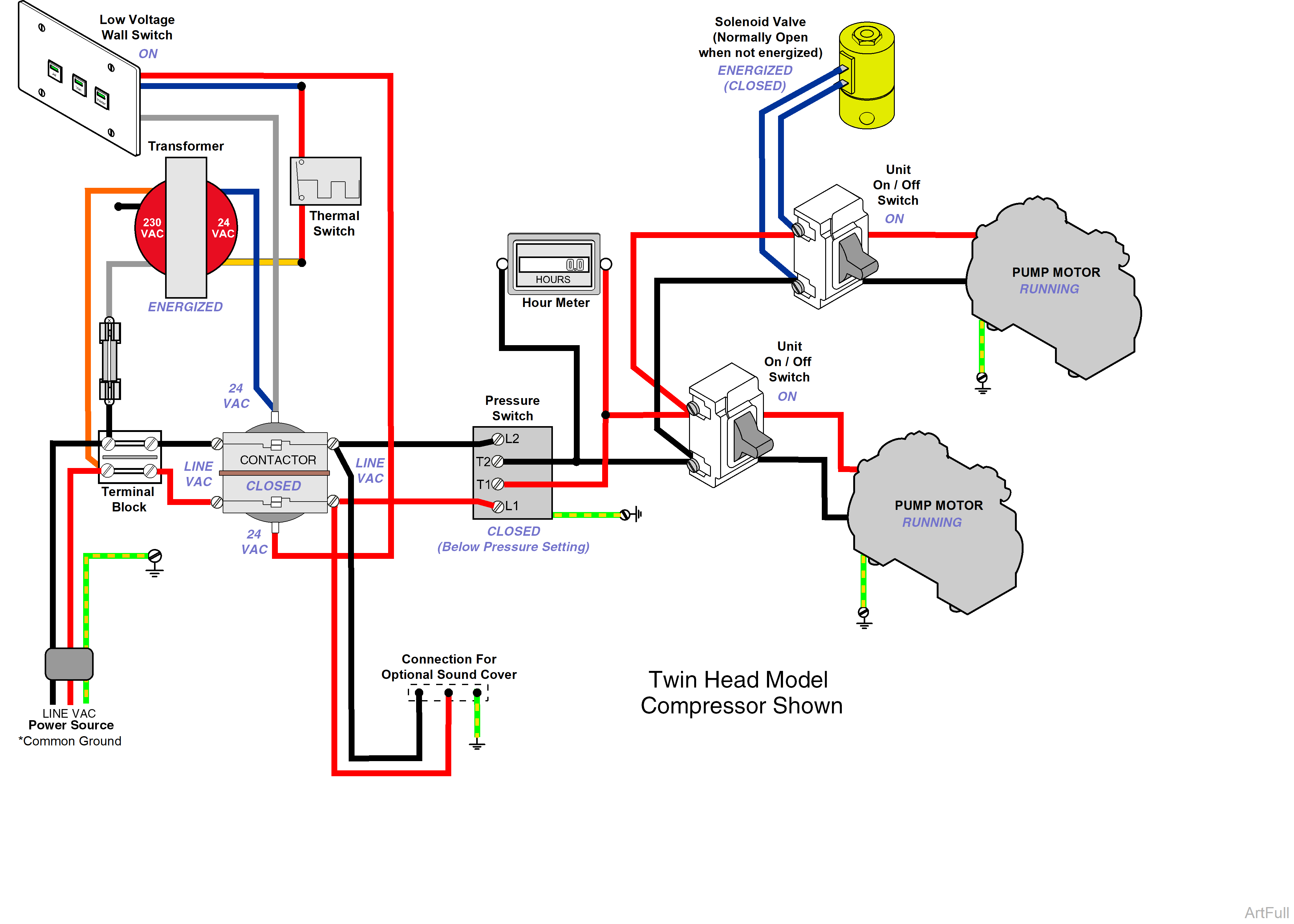
•Line voltage from the power source is always present on one side of the contactor contacts.
•Line voltage is also being supplied to the 240 / 24 VAC transformer energizing it.
•Transformer supplies 24 VAC to the low voltage wall switch and to one side of the 24 VAC contactor coil. When the low voltage wall switch is on it completes the 24 VAC circuit to the contactor coil energizing it and closing the contacts.
•With the contacts closed, line voltage is supplied to the pressure switch.
•Pressure switch contacts open and close to regulate tank pressure by closing it's contacts when the tank pressure drops to 80 PSI + / - 5 PSI or below and will open the contacts when tank pressure reaches 100 PSI max. + / - 5 PSI shutting off compressor.
•Line voltage then supplied to the unit on/off switches when turned on, line voltage is supplied to the motors.
• Line voltage is also supplied to the normally open solenoid valve closing the valve when the compressor is running preventing compressed air from being discharged through the solenoid valve. When the compressor is not running the solenoid valve is open allowing the compressor to purge.
