PowerAir Purge Cycle Theory of Operation
Under normal operation conditions, a small amount of moisture may be under the unloader exhaust muffler. This is not a malfunction. It is evidence of what the filter on the Desiccant Drying System captured the moisture, and did not permit it to enter the operatory air supply.
The pressure switch will open at 100 PSI max +/_ 5 PSI, shutting off electrical current to compressor head(s) and the solenoid/purge valve.
At the same time the normally open solenoid/purge valve mechanically opens, starting the purge cycle.
Air from the purge tank flows back through the metered orifice inside the purge check valve.
The clean dry air drives out the moisture from the desiccant beads through the coalescing filter housing, normally open solenoid valve and out the drain/exhaust muffler.
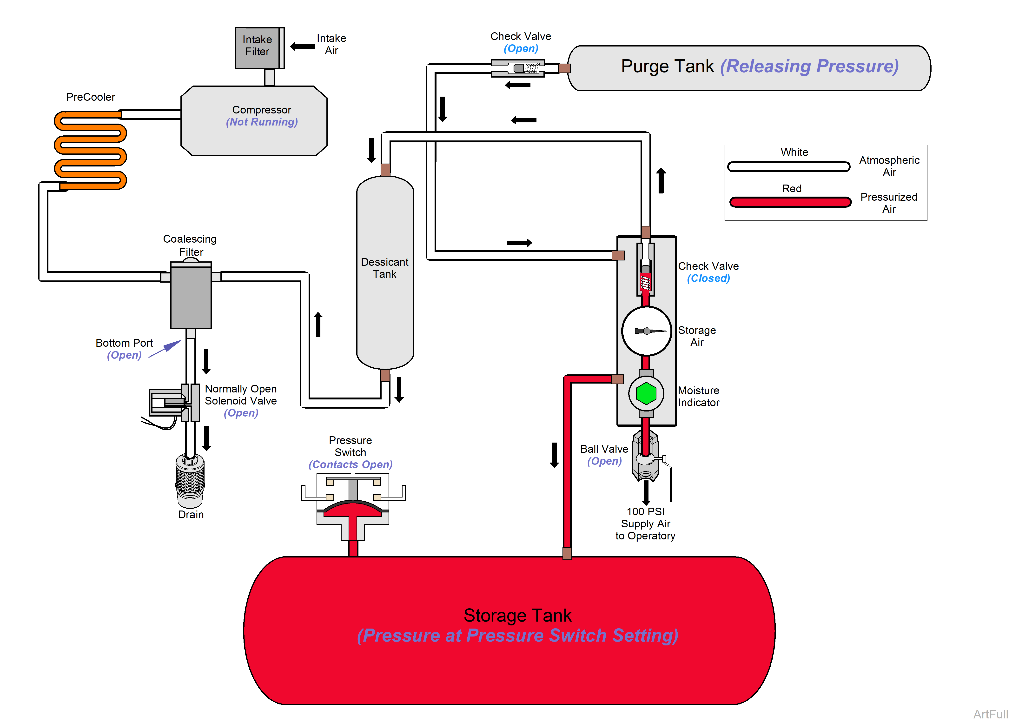
The compression and purge cycles will continue as the pressure inside the system fluctuates between the 80 PSI and 100 PSI pressure settings.
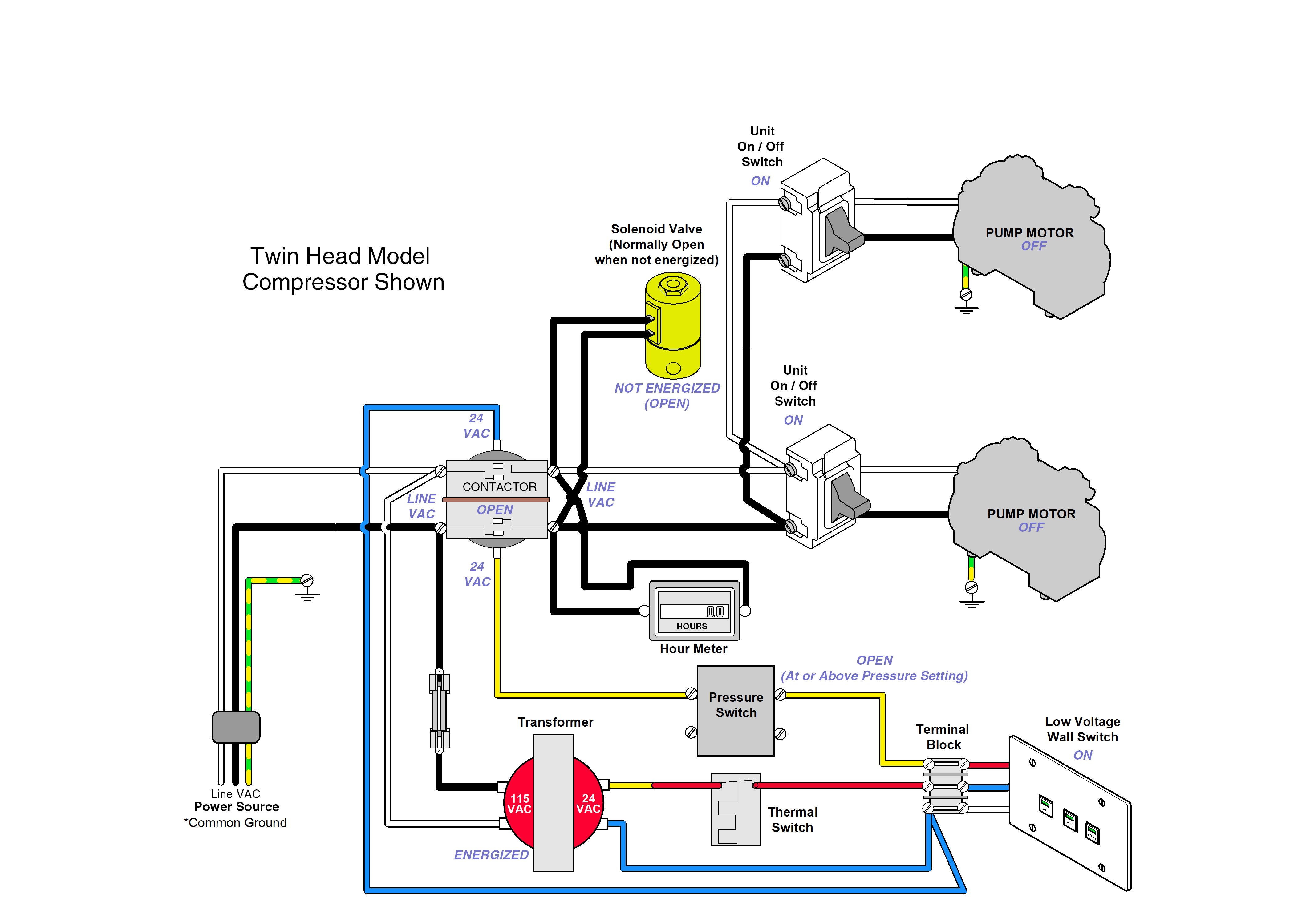
•Pressure inside the system reaches 100 PSI (+ / - 5 PSI) causing pressure switch contacts to open.
•Power is removed from the coil of the contactor which opens the contactor tips, opening the power circuit stopping the motor.
•At the same time, power is removed from the normally open solenoid valve, opening the valve. This allows pressure to be released from the top of the compressor head and purge tank through the desiccant tank out the exhaust muffler.
The compression and purge cycles will continue as the pressure inside the system fluctuates between the 80 PSI and 100 PSI pressure settings.
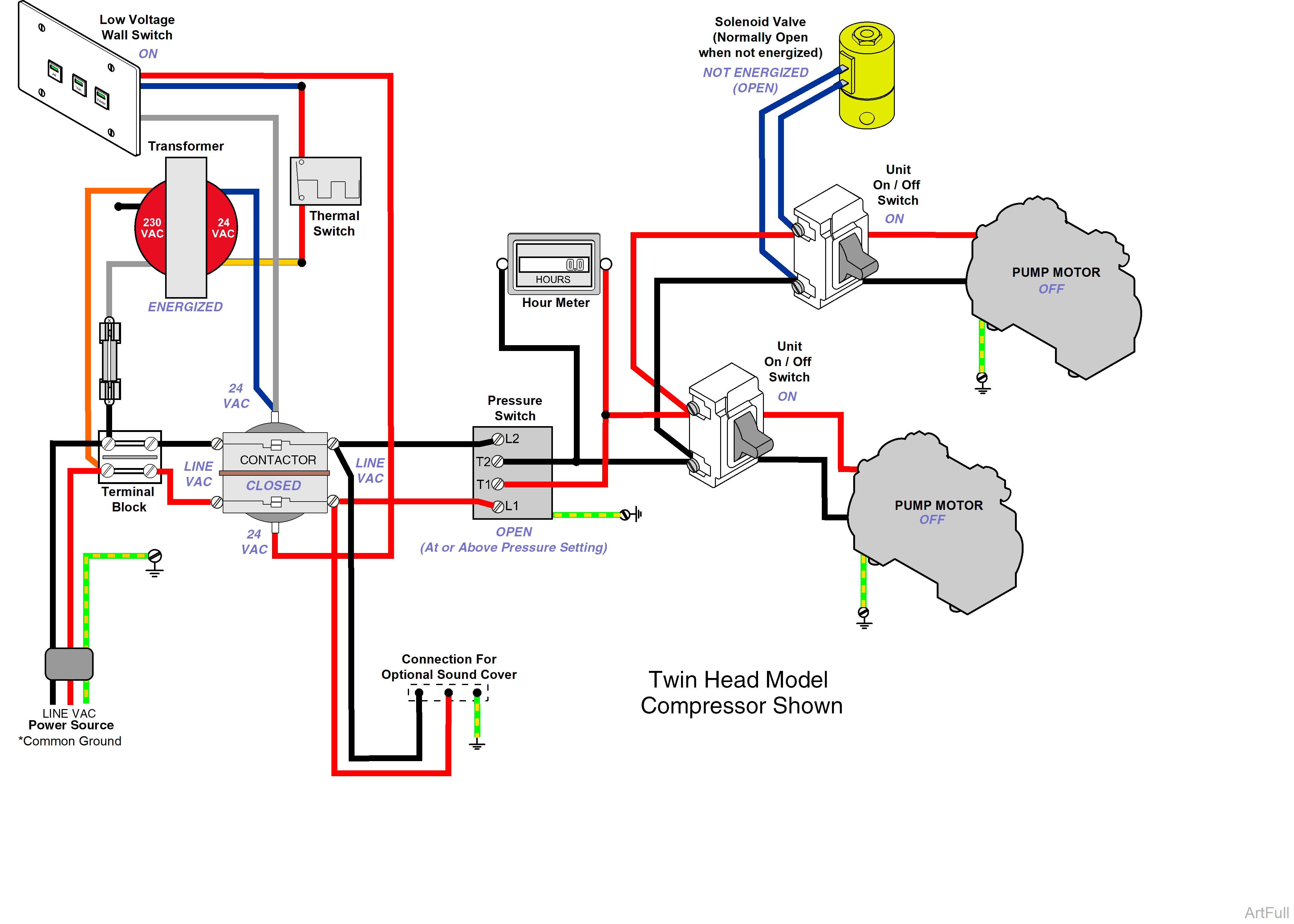
•Pressure inside the system reaches 100 PSI (+ / - 5 PSI) causing the pressure switch contacts to open.
•Open contacts of the pressure switch removes line voltage from the hour meter, unit on/off switches stopping the motors.
•At the same time, power is removed from the normally open solenoid valve, opening the valve. This allows pressure to be released from the top of the compressor head and purge tank through the desiccant tank out the exhaust muffler.
