PowerVac G Float Assembly Test and Repair
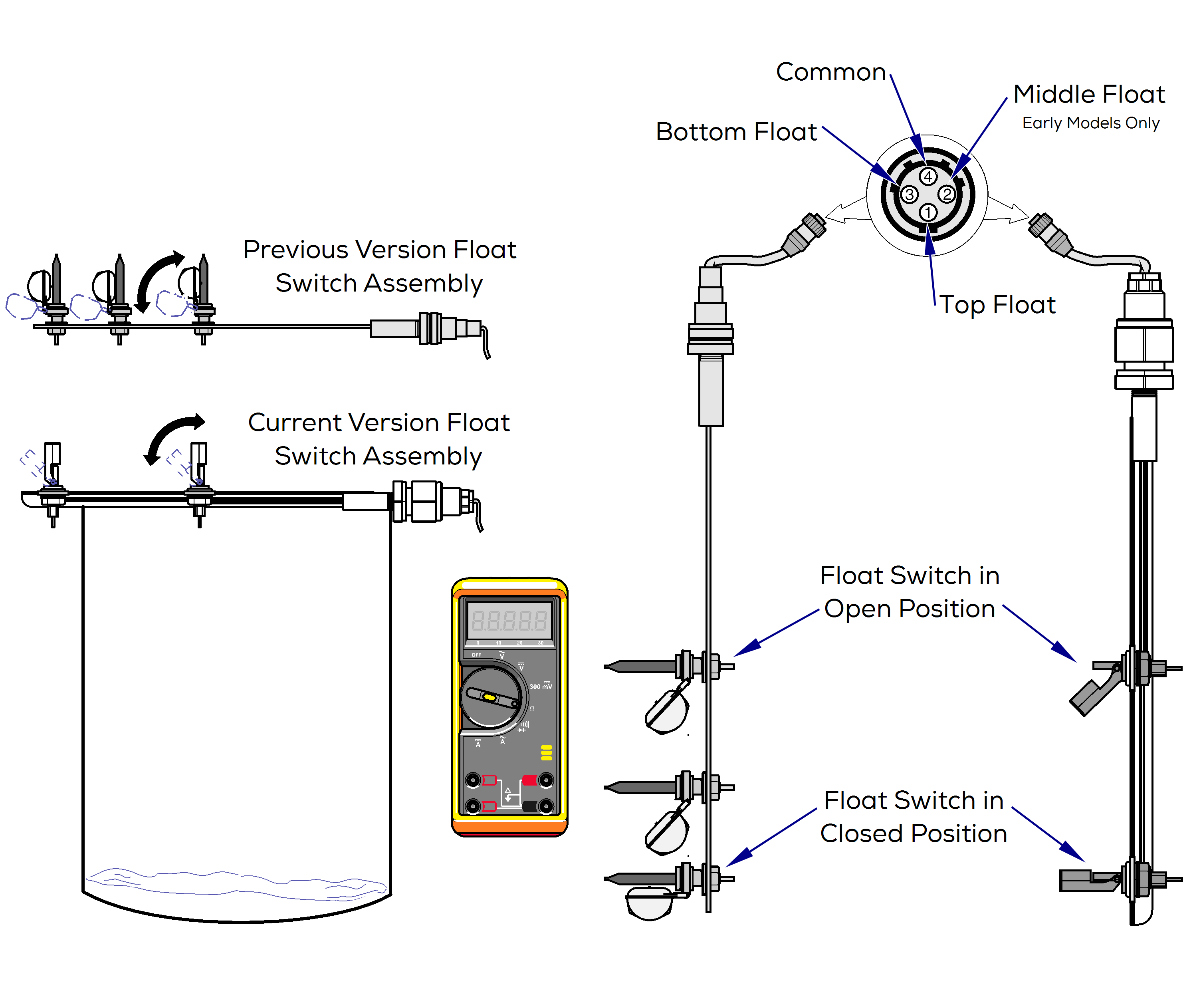
Earlier production units had three reed switch floats. The middle float was not used and is not installed in current production units.
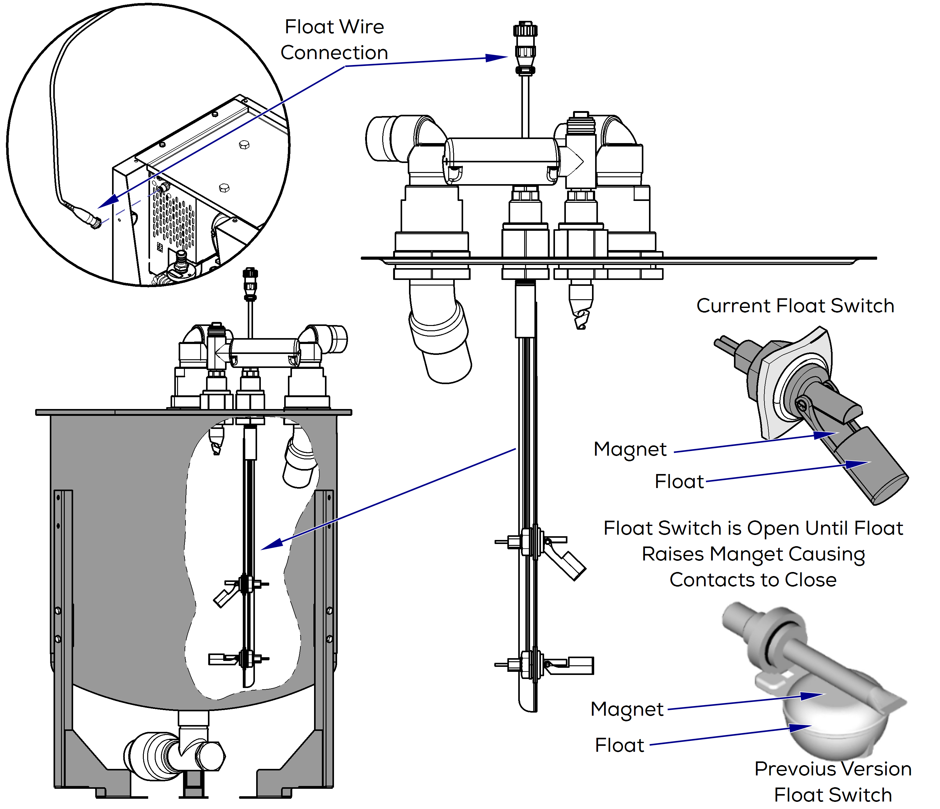
On earlier production units, the float assembly contained three float (reed) switches mounted on a bracket at different intervals. Current units only have two float switches.
The reed switch has contacts that remain open until the liquid in the separator rises, causing the float to rise until the magnet contacts the reed switch.
When the magnet contacts the reed switch, the open contacts inside the reed closes.
When the top float switch closes, the vacuum pump stop running until the bottom float opens and the cycle starts again.
The upper and lower floats interact as a latching circuit with the internal relay to release upon drain below the bottom float. The magnet in the float is to activate the reed switch within the stem.
Running pump with float wire connection removed from base other than to briefly troubleshoot can cause damage to the pump.
When working on Twin units, unplug parallel harness.
1.Turn power off at on/off switch.
2.Remove float wire connection from rear of base by un-threading connector and removing.
3.Turn power back on at on/off switch.
4.If pump runs, the tank is either full (not draining) or there is a issue with the floats. Proceed to next section.
5.If the pump doesn’t run, proceed with troubleshooting the pump base.
| Check | Results | Required Action |
|---|---|---|
| Float connection removed from base | Pump starts running | Troubleshoot floats |
| Pump still not running | Troubleshoot Pump |
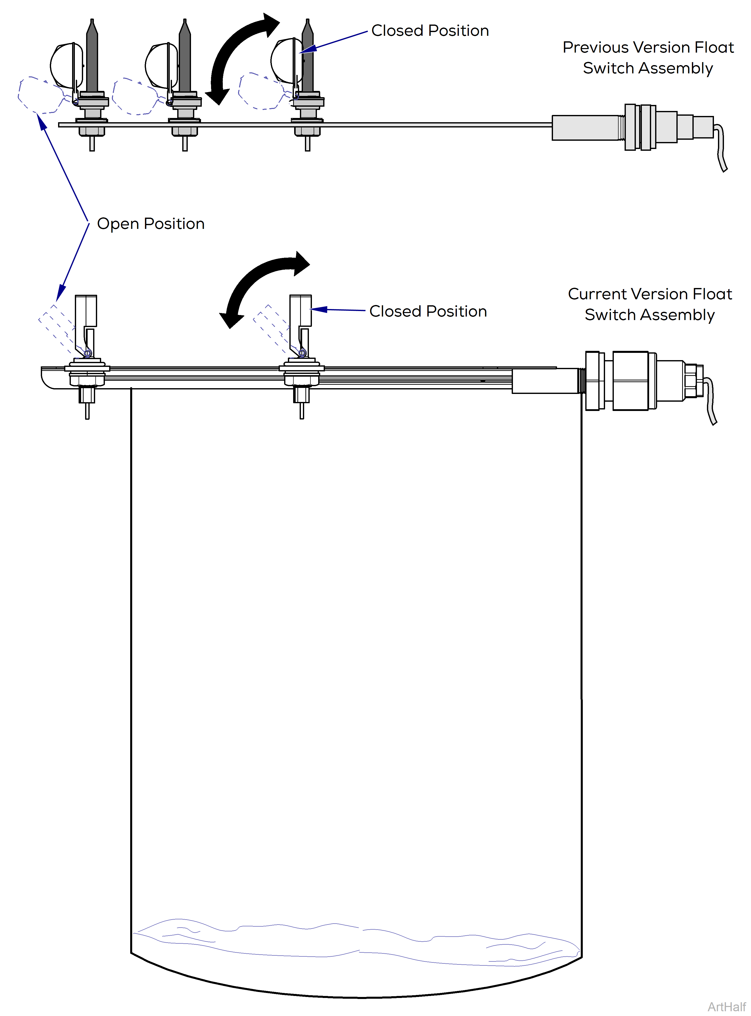
Earlier production units had three reed switch floats. The middle float was not used and is not installed in current production units.
A quick test to see if the floats are preventing the pump from running (full tank) is to unplug the float switch assembly from the front of the vacuum base. The pump will run if the issue is with the floats or tank is full. This is for testing purposes only! Continuing to run the vacuum with this connector unplugged can cause damage to the pump.
1.Turn power off at on/off switch and main power supply box.
2.Remove gasket on separator lid.
3.Lift lid/float assembly out of tank and lay across top of tank, put floats in down position.
4.Remove electrical panel cover.
5.Turn supply power and unit ON.
6.Set meter to Ω.
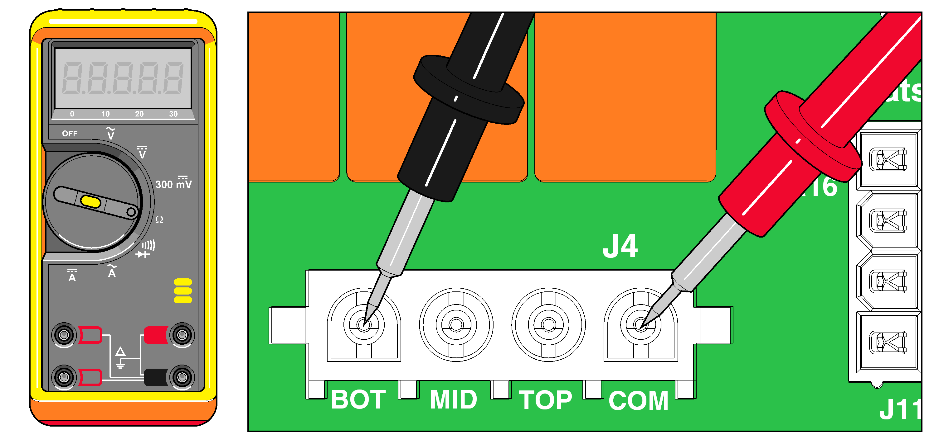
7.Lift bottom float to closed position. Measure resistance from COM to BOT, MID, and TOP at J4 on PC board. Verify bottom float LED light is “On”, on the PC board while float is closed. Repeat for the middle and top floats.
8.With all floats closed, lower the top float to the down position, then middle float, and finally the bottom . The motor should not start until the bottom float is down.
Verify readings are within range. If not, check float harness continuity.
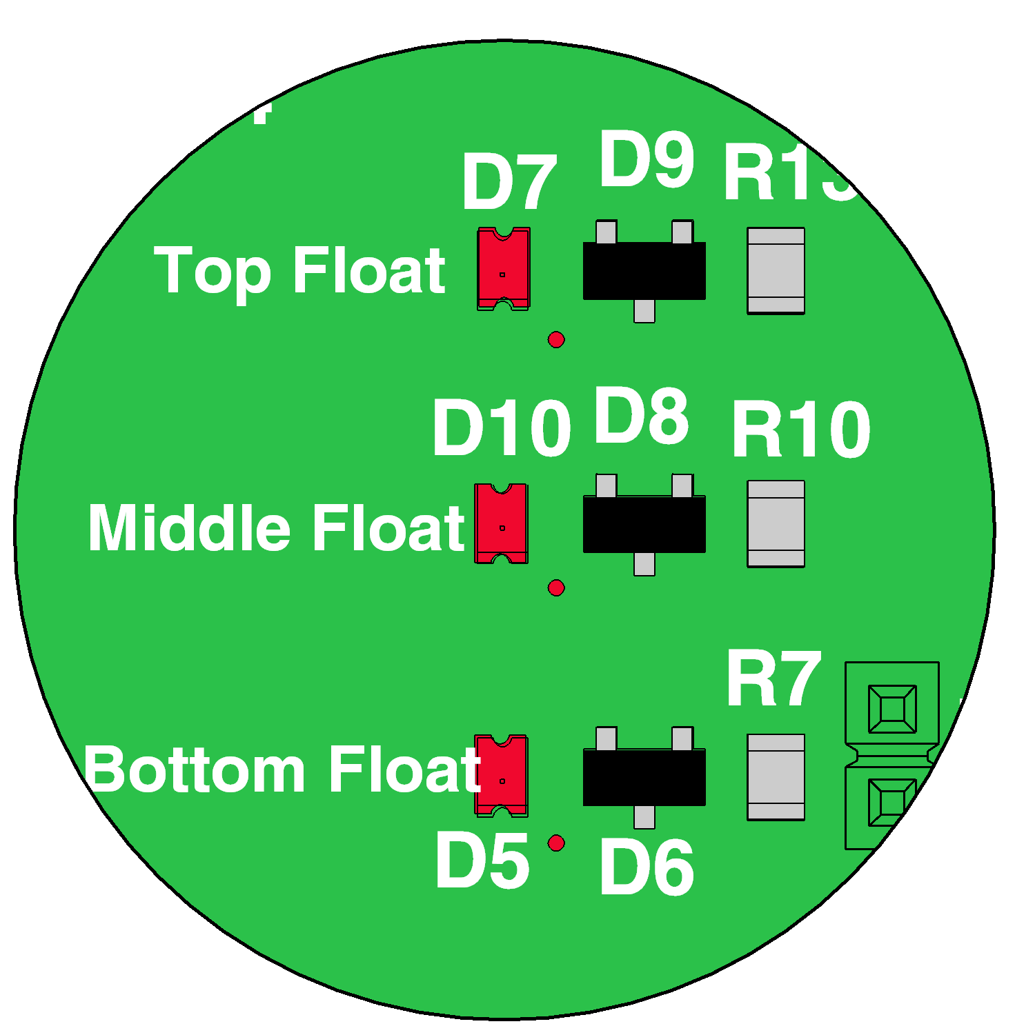
LEDs on PC board
Earlier production units had three reed switch floats. The middle float was not used and is not installed in current production units.
| LED’s on PC board | Indicate |
|---|---|
| D5 – Bottom Float | Bottom float switch is closed |
| D10 – Middle Float | Middle float switch is closed |
| D7 – Top Float | Top float switch is closed |
| Check | Meter Reading | Required Action |
|---|---|---|
| With float up | < 5 ohms | Ok |
| With float down | OL |
Ok |
| Float up or down | Out of range | Check float harness continuity |
1.Turn power off and unplug float harness from base unit.
2.Lift lid/float assembly out of tank and lay across top of tank.
3.Move floats to down position.
4.Set meter to Ω. Probe end of float harness, each pin 1, 2, and 3 to pin #4. When checking each float perform steps D thru F.
5.Lift bottom float to closed position.
6.Measure at the harness between pin #4 and the pin of the raised float #3. Verify readings are within range. If not, replace float assembly.
Motor should stop after top float switch is raised.
| Check | Meter Reading | Required Action |
|---|---|---|
| With float in closed position | < 5 ohms | Ok |
| With float in down position | OL |
Ok |
| Float up or down | Out of range | Replace float harness |
