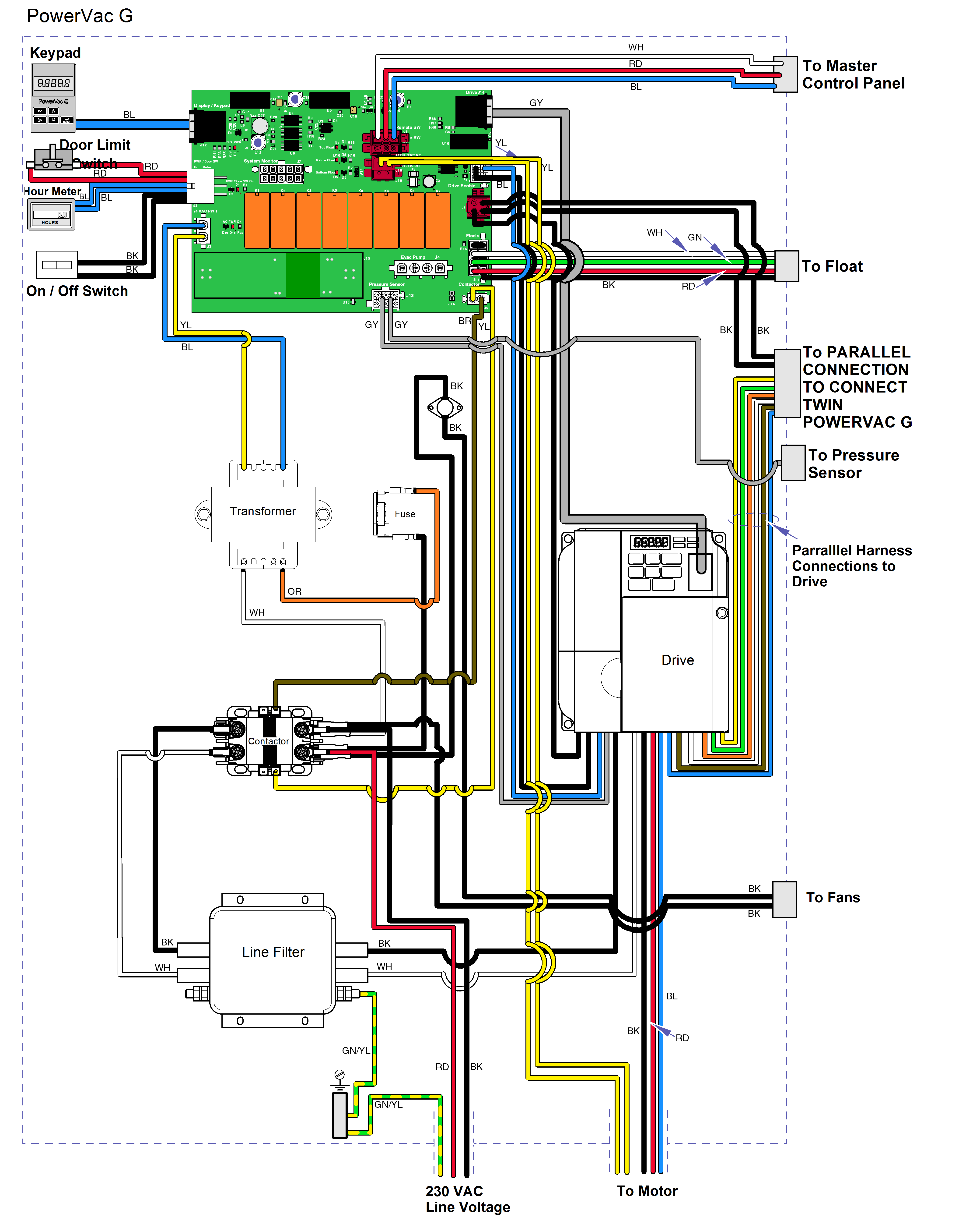
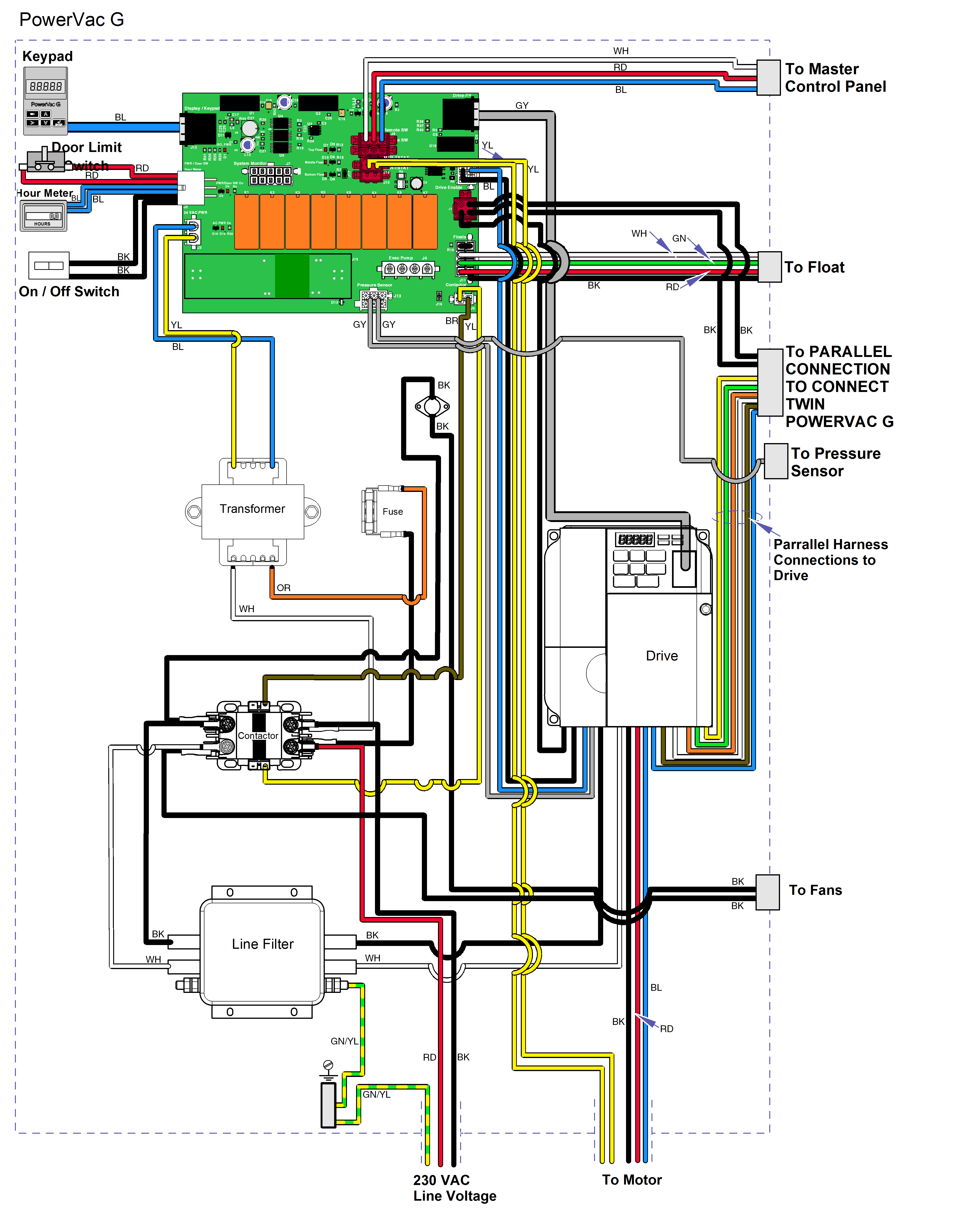
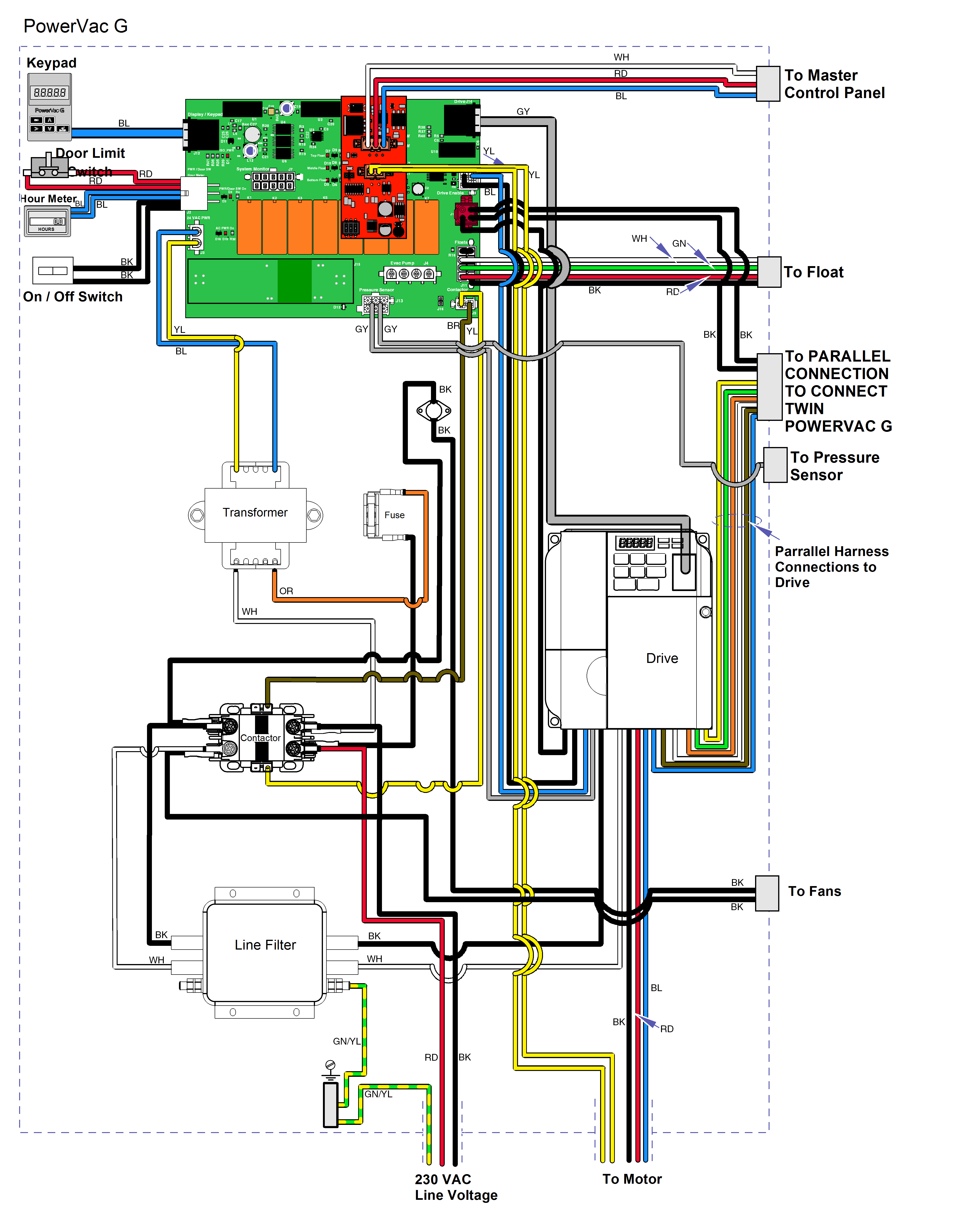
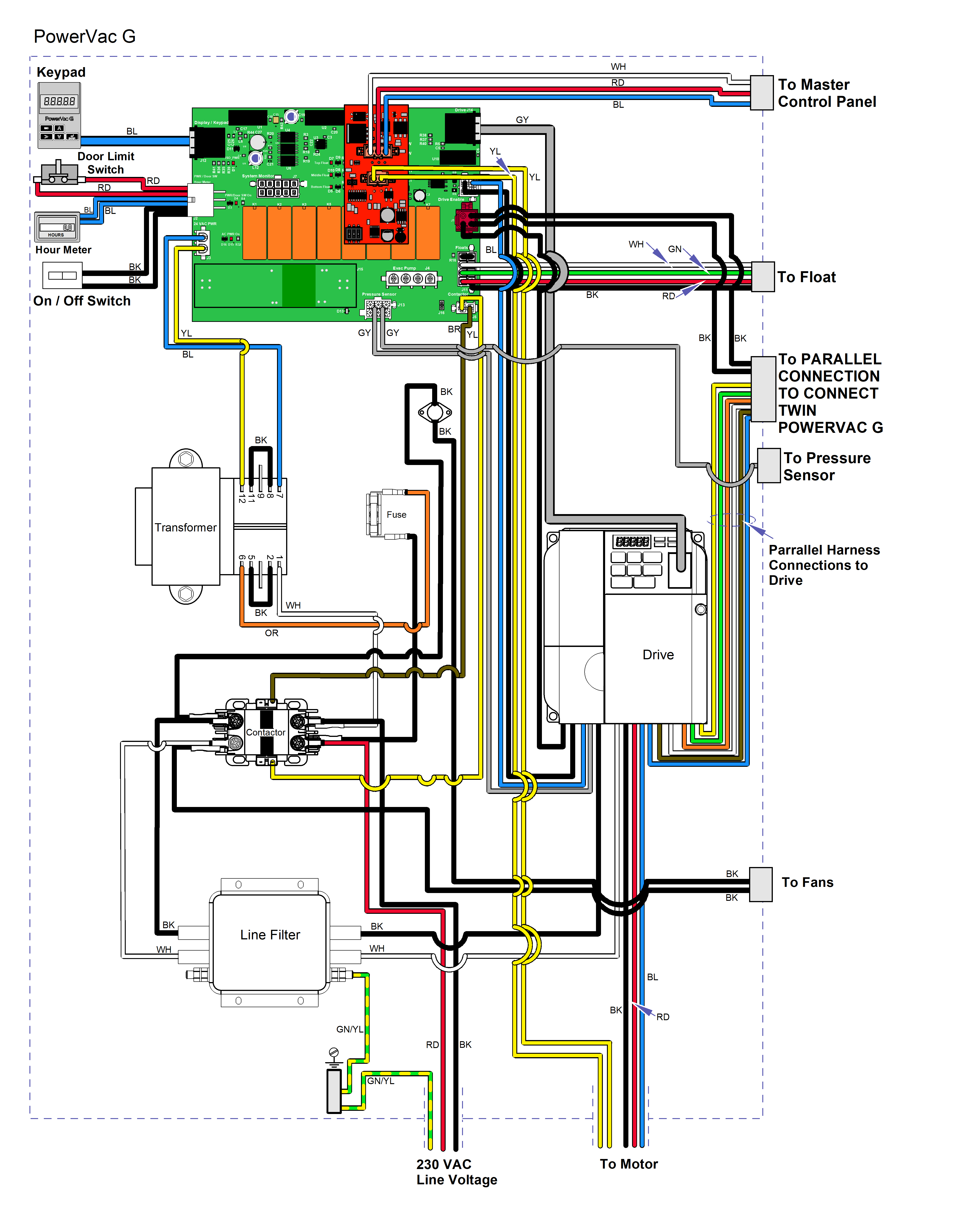
PowerVac G Wiring Diagram
|
Model |
All |
| Serial Number | V998996 to V1093822 |
|
Model |
All |
| Serial Number | V1093823 to V1648734 |
|
Model |
All |
| Serial Number | V1648735W to V2726346 |
|
Model |
All |
| Serial Number | V2726347 to Present |
|
Model |
All |
| Serial Number | All |
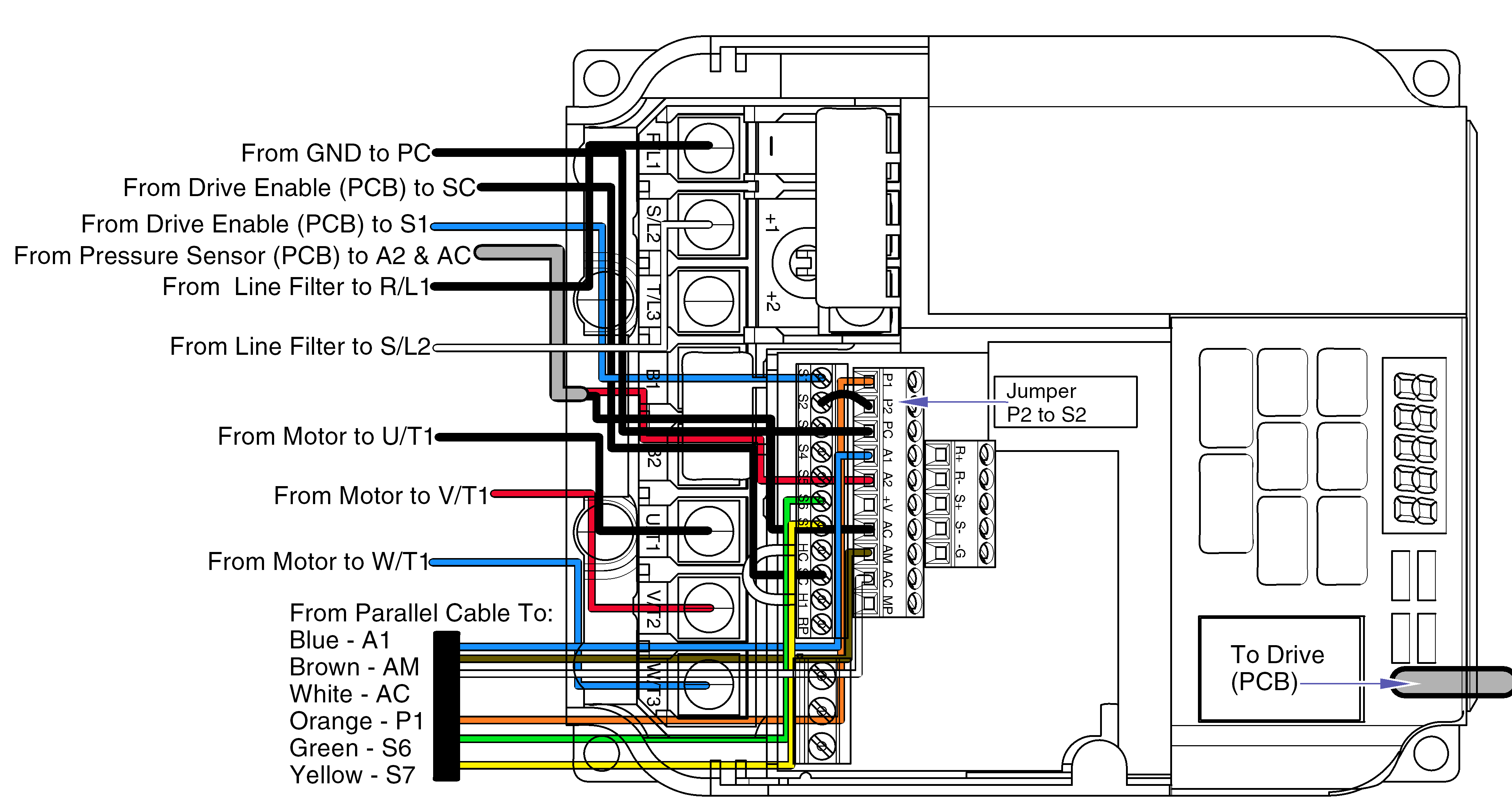
|
Model |
All |
| Serial Number | V998996 to V2347937 |
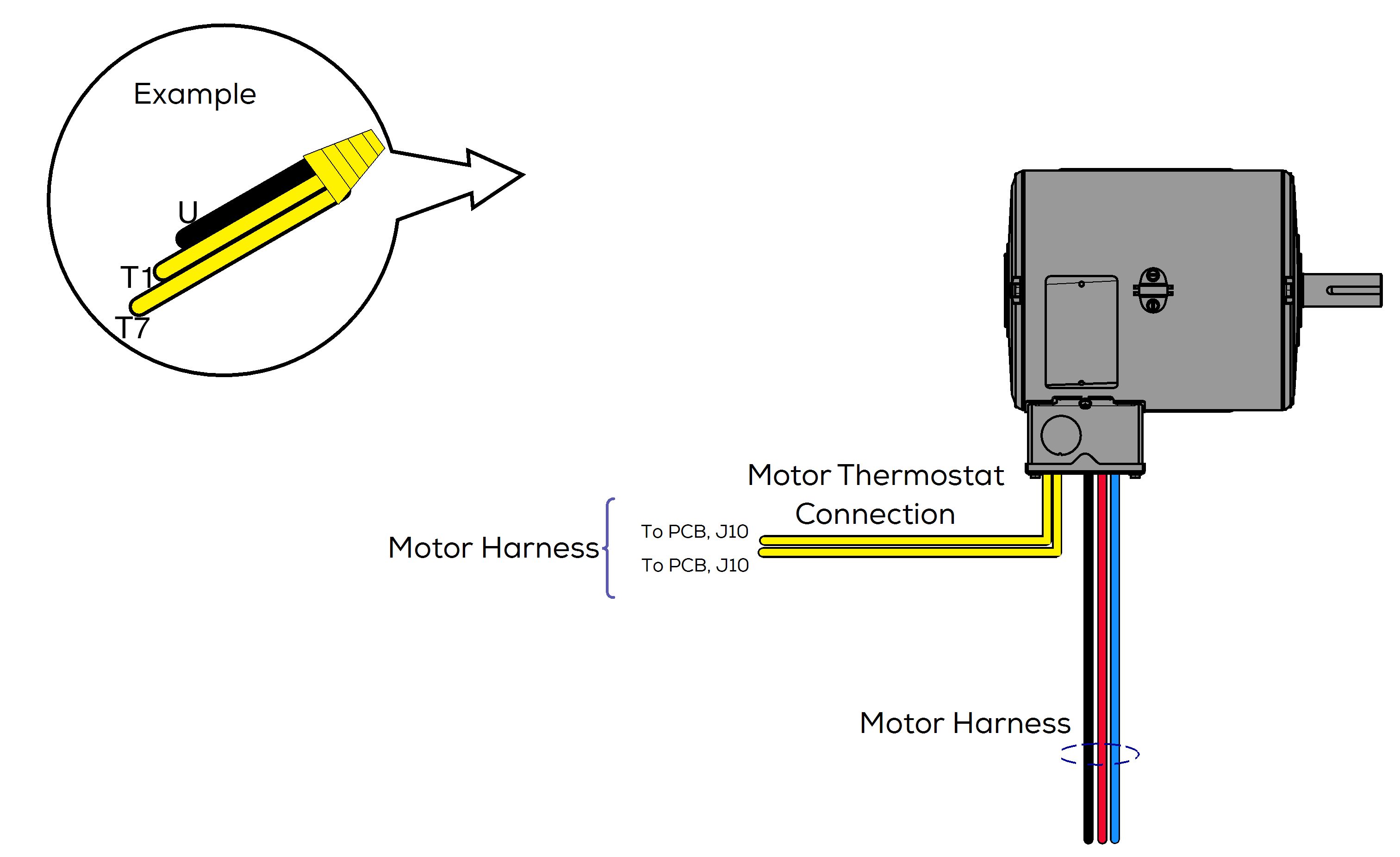
| Motor Harness To Controller | Motor Wires |
|---|---|
| U (Black) | T1 / T7 (Yellow) |
| V (Red) | T2 / T8 (Yellow) |
| W (Blue) | T3 / T9 (Yellow) |
| -- | T4 / T5 / R6 (Yellow) |
| 1 Yellow | 1 Red |
| 1 Yellow | 1 Red |
|
Model |
All |
| Serial Number | V2347938 to Present |
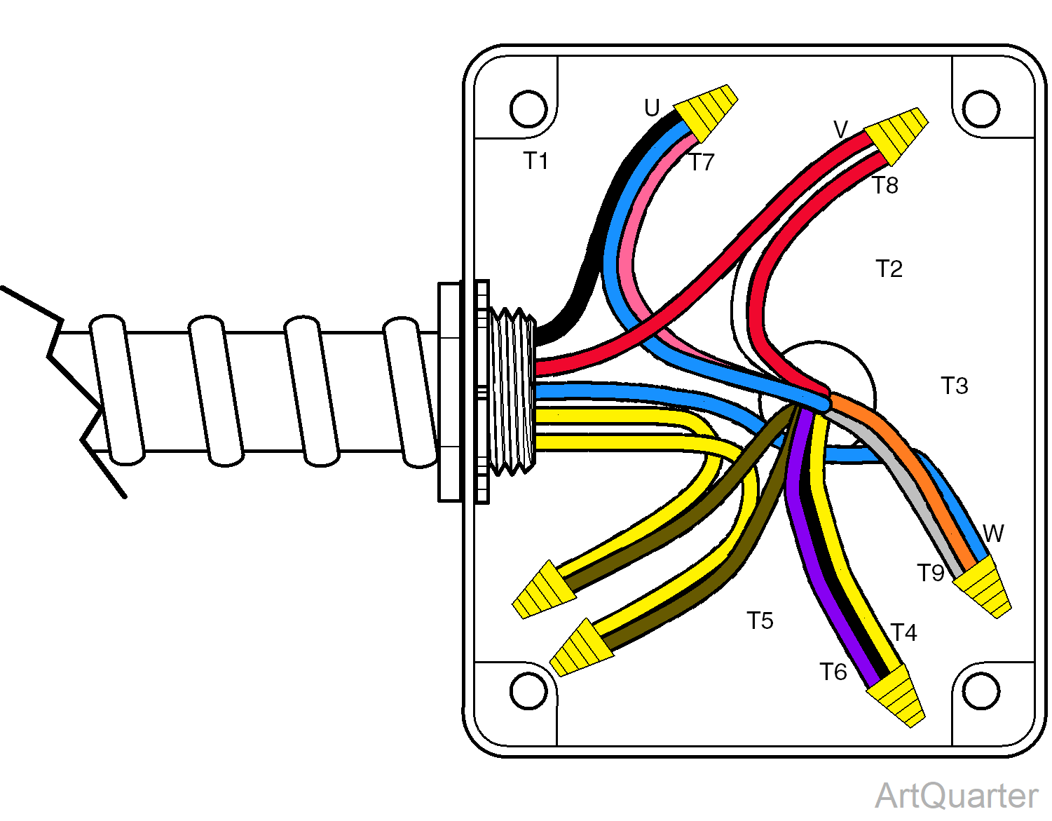
| Motor Harness To Controller | Motor Wires |
|---|---|
| U (Black) | T1 / T7 (Blue /Pink) |
| V (Red) | T2 / T8 (White /Red) |
| W (Blue) | T3 / T9 (Orange /Grey) |
| -- | T4 / T5 / T6 (Yellow / Black / Purple) |
| 1 Yellow | 1 Brown |
| 1 Yellow | 1 Brown |
|
Model |
All |
| Serial Number | V1093823 to Present |
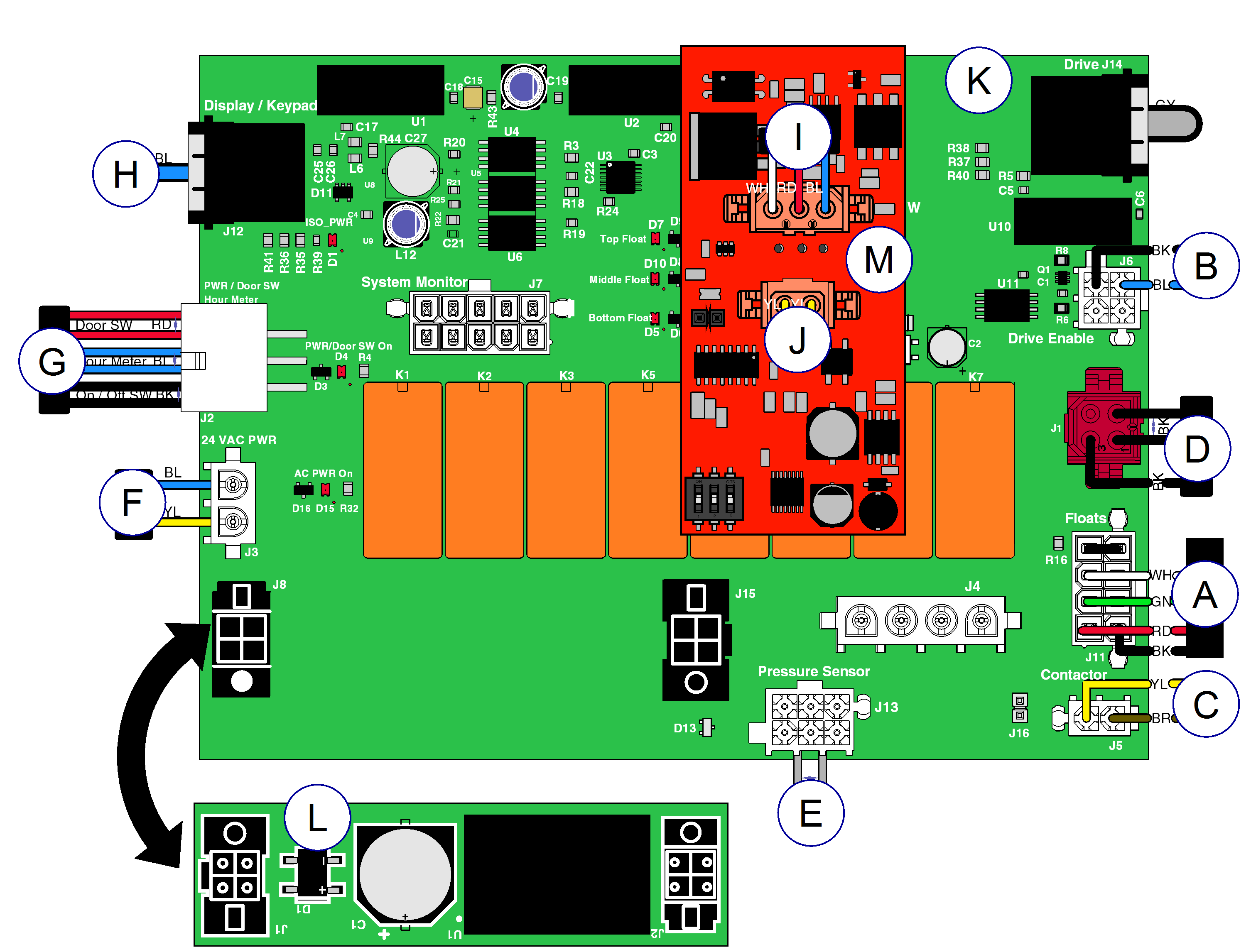
| Item | Part Number | Description |
|---|---|---|
|
A |
015-2736-00 | Float Harness - Inside, Float Cord is part of the Float Assembly |
|
B |
015-2740-00 | Drive Harness |
|
C |
015-2725-00 | Contactor Harness |
|
D |
Harness Options | |
|
|
015-2749-00 | Paralleling Harness - Inside Box |
| 002-1443-00 | Paralleling Harness - Between Vacuums, Lead Vacuum End has 4 pins and Controlled Vacuum End has 6 pins | |
|
E |
015-2724-00 | Pressure Sensor Wire Harness |
|
F |
002-1442-00 | 24 VAC Harness |
|
G |
015-2741-00 | Switch and Hour Meter Harness |
|
H |
015-2756-00 | Keypad CAT5 Cable |
|
I |
015-2743-00 | Remote Harness |
|
J |
015-2742-00 | Motor Thermostat Harness |
|
K |
015-2700-00 | PC Board |
|
L |
015-2815-00 | Power Supply Assembly |
|
M |
002-1910-03 | PVAC Timer |
|
N |
002-1492-00 | Fan Harness - Inside - Not Shown |
|
O |
015-2746-00 | Cord, Daisy Chain, Fan - Outside - Not Shown |
|
P |
015-1896-00 | 6 footElectrical Conduit - Base Unit to Disconnect Switch Box - Not Shown |
| Color Abbreviation Chart | ||
|
NSS = Not Sold Separately | AR = As Required | NLA = No Longer Available | CFN = Call for Number Always Specify Model and Serial Number |
||

