PowerVac® P Door Limit Switch and Circuit Breaker On/Off Switch Test and Repair
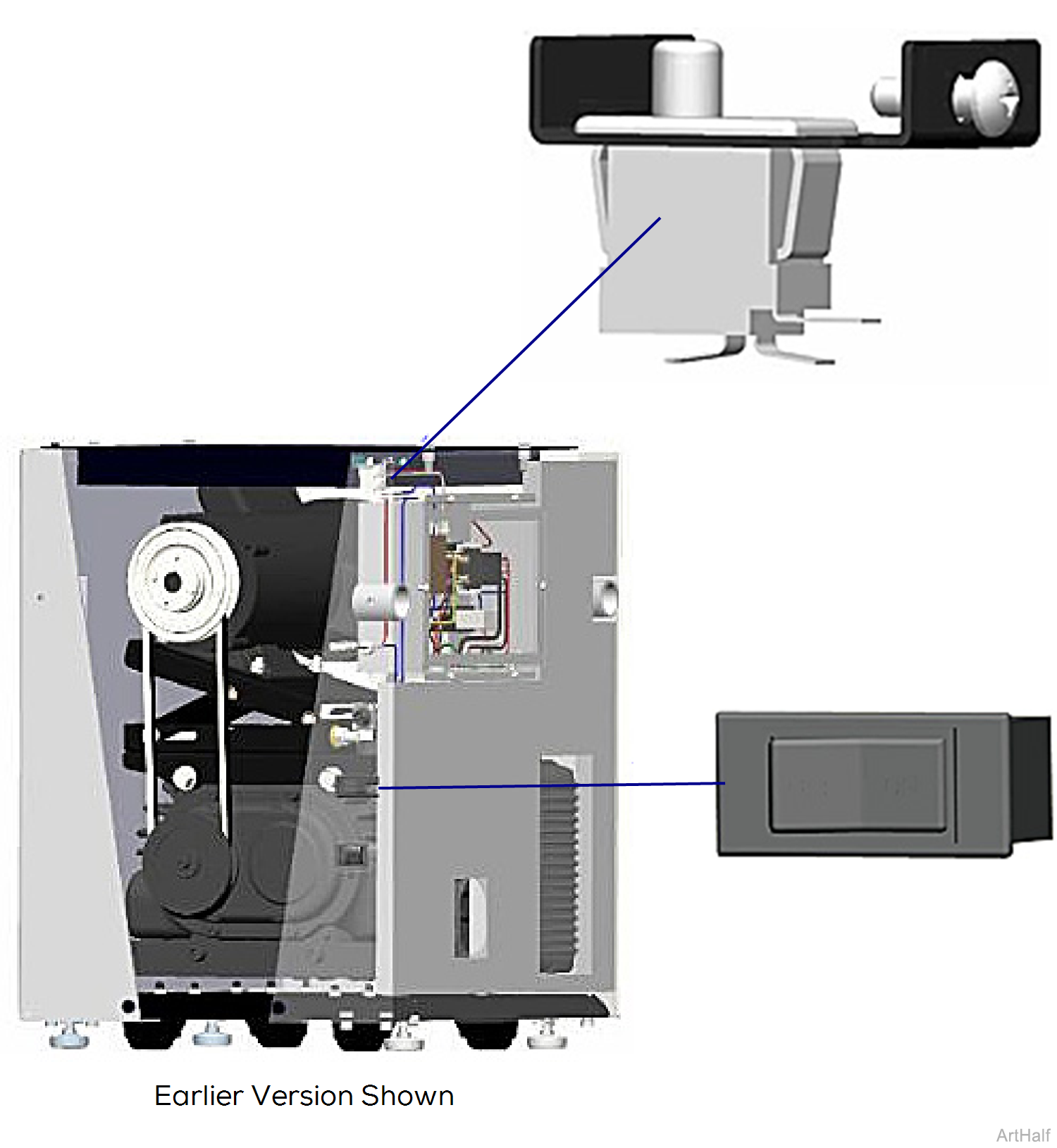
With facility power (230 VAC) supplied to the system, the transformer continuously supplies 24 VAC to the normally-open door limit switch.
With the front access cover in place, the plastic bumper on the top right side of the access cover, trips the door limit switch causing it to close.
When the limit switch is closed, 24 VAC flows through the switch to the PowerVac® circuit breaker (ON / OFF Switch). With the circuit breaker switch ON, current is supplied to the remote wall switch (if applicable).
If the facility does not have a remote wall switch, the PowerVac® circuit breaker serves as the ON/OFF switch for the system.
When the front access cover is removed, the door limit switch opens and stops current flow to the PowerVac® circuit breaker. This is a safety feature that prevents the system from operating with the cover removed.
When testing components with power on, use care to prevent electrical shock.
Door limit switch is a safety device. If switch is not working, do not bypass. Warranty will be void if switch is bypassed. If both tests fail, it must be replaced!
1.Turn power off.
2.Remove front cover. Refer to: Front Cover
During step 3, the motor belt and pulley may spin with front cover off. Stay clear and keep everything out of the vacuum base!
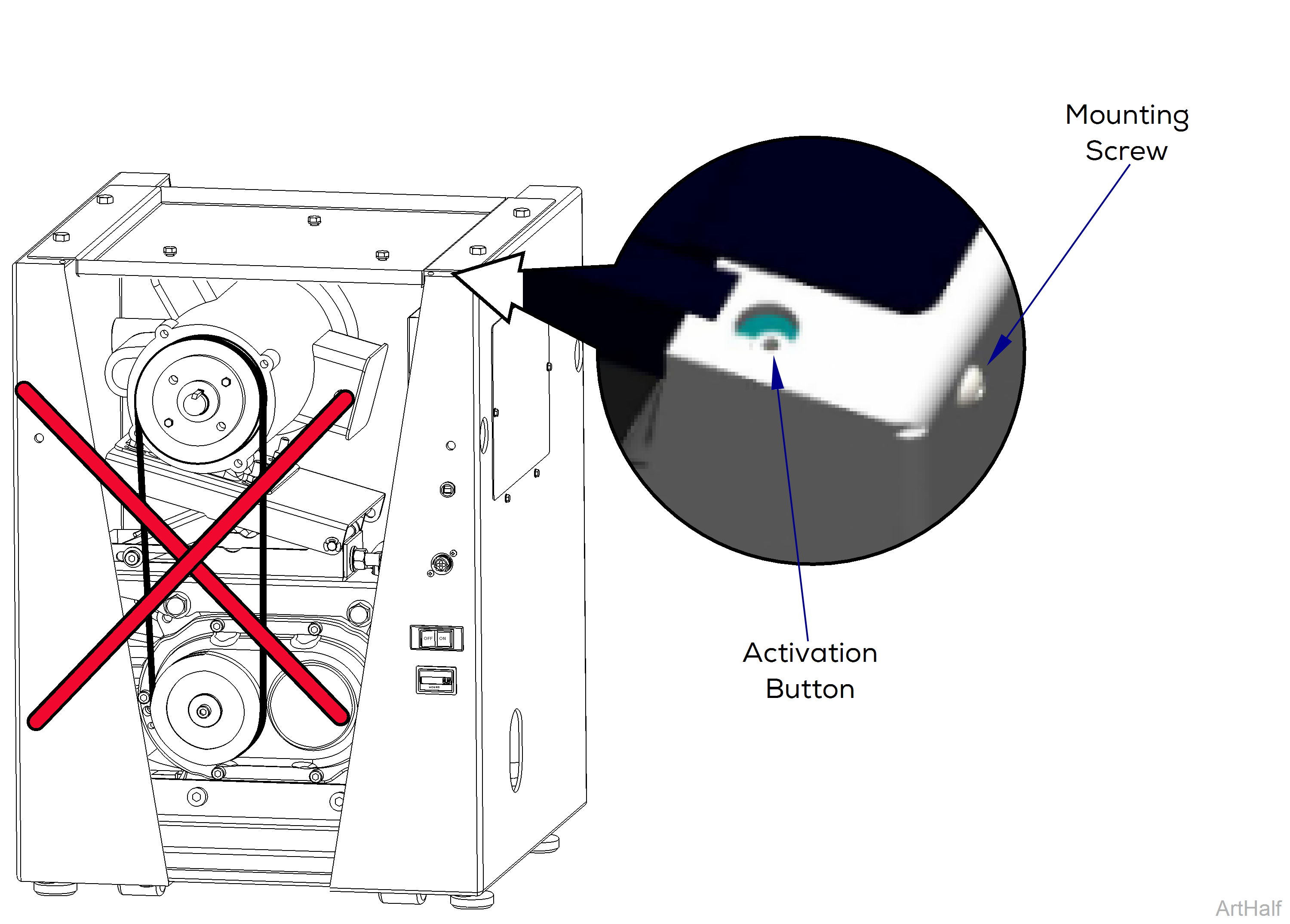
3.Turn power on and depress activation button with a screwdriver.
If motor starts up, quickly take pressure off switch. Plastic bumper may be obstructed or damaged. Check plastic bumper on door for damage. If it is damaged, switch it with plastic bumper on opposite side of door until a replacement can be ordered. If motor doesn't start, continue with step 4.
4.Turn power off.
5.Remove mounting screw for door limit switch. Disconnect electrical leads.
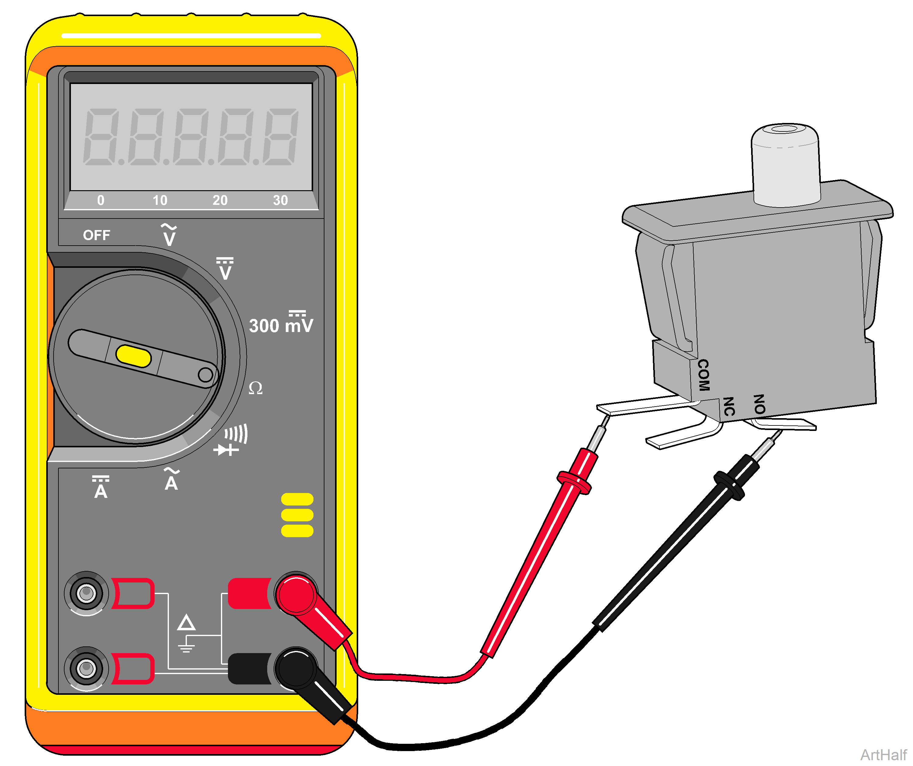
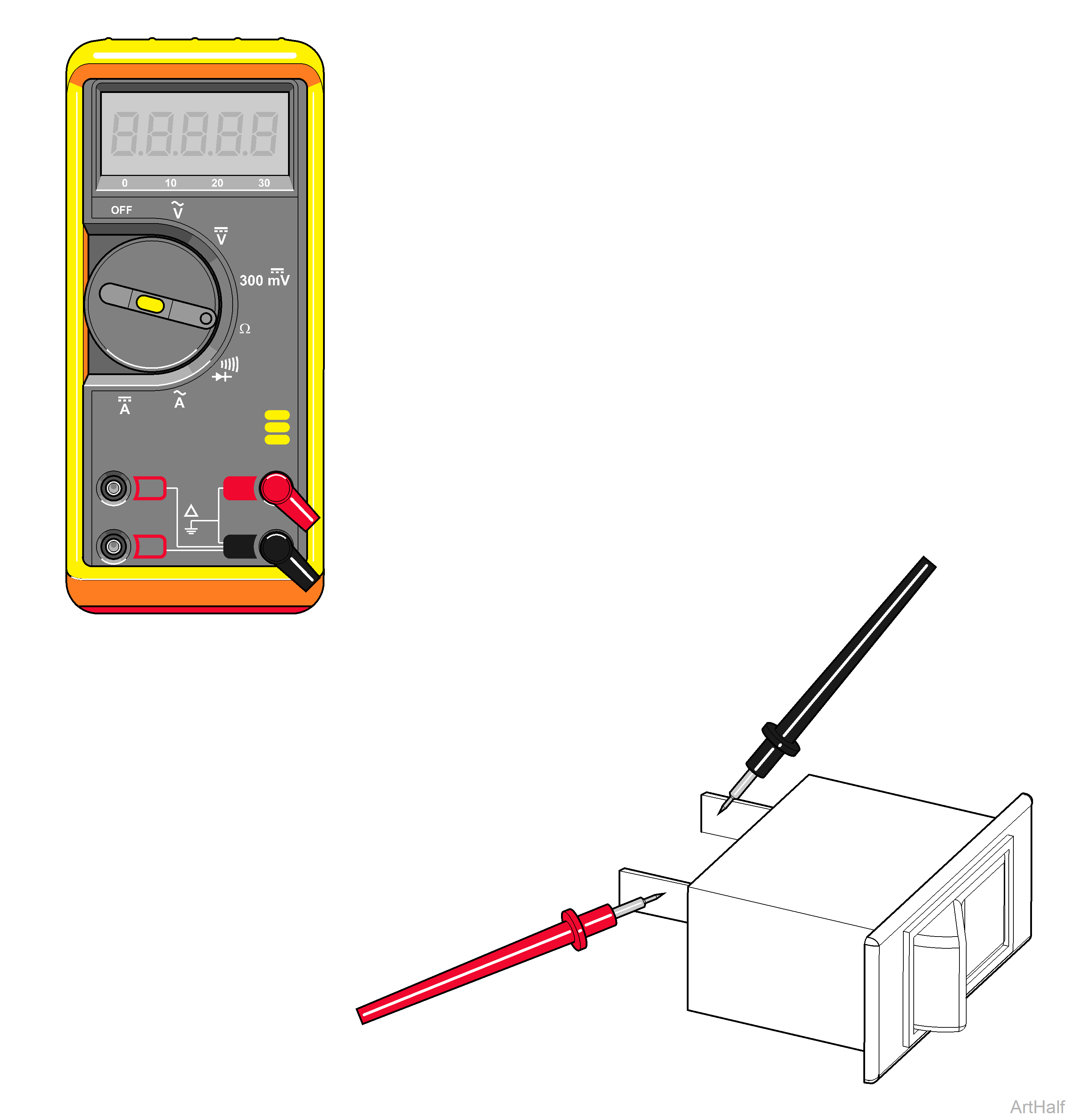
6.Test continuity. Set meter to Ω. Place meter probes on COM and NO terminals.
Check switch tripped and untripped below.
7.Install front cover.
| With Switch Untripped | ||
|---|---|---|
| Meter Reading | Status | Required Action |
| OL |

|
Limit switch okay. |
| Less than 5 Ω |

|
Replace switch. |
| With Switch Tripped | ||
|---|---|---|
| Meter Reading | Status | Required Action |
| OL |
|
Replace switch. |
| Less than 5 Ω |
|
Limit switch okay. |
Motors installed after 12/08 are thermally protected with automatic reset. Unit may start without warning.
The On/Off switch controls only the secondary circuit power. The main power source must be turned off to remove all power in the control box. Vacuum system must not have power when front cover is off base unit.
1.Disconnect power at on/off switch and main power supply box.
2.Remove front cover. Refer to: Front Cover
3.Disconnect wires from limit switch.
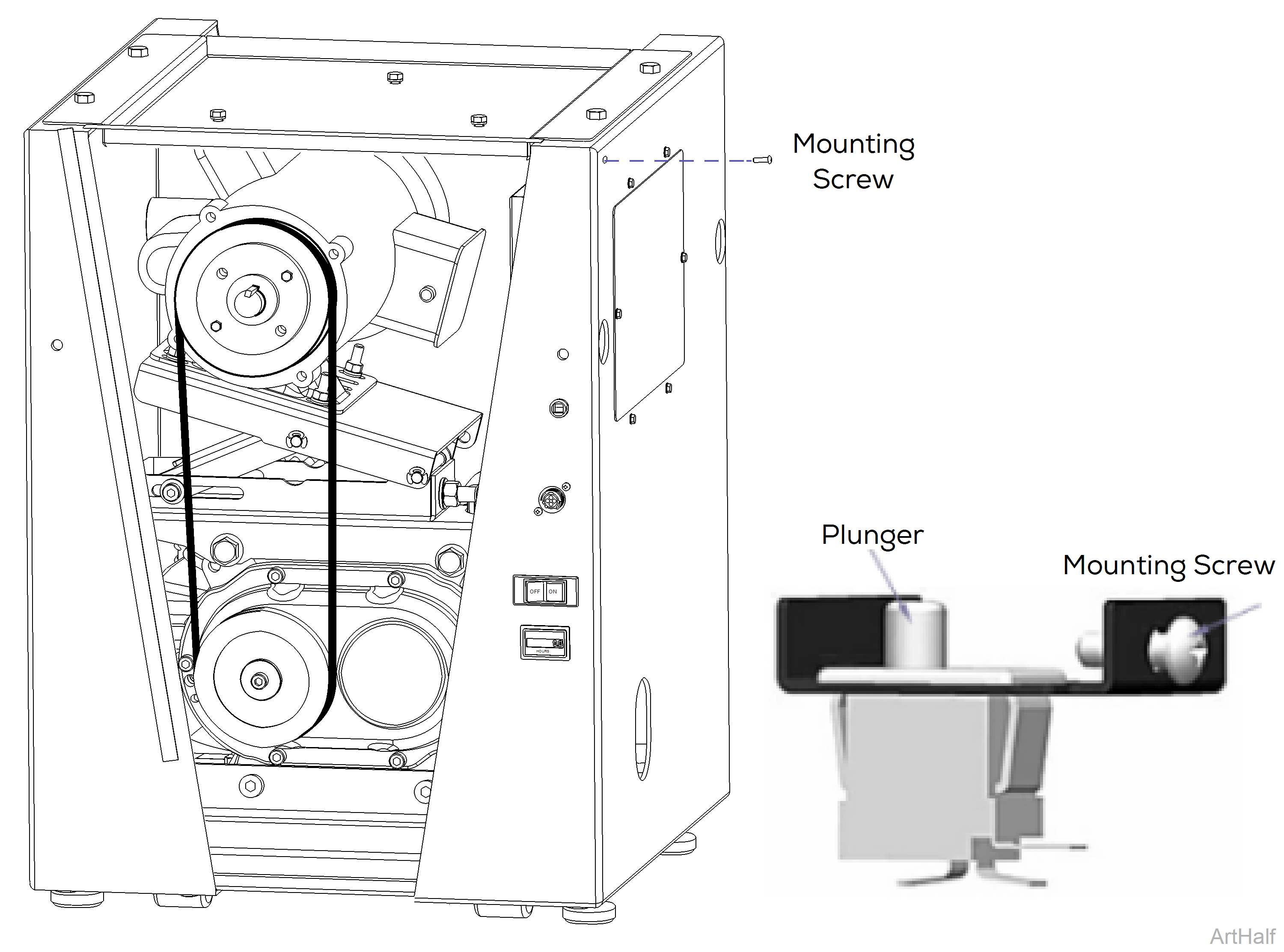
4.Remove mounting screw and pull out limit switch and bracket. Remove switch from bracket.
5.Align limit switch with hole in side panel and plunger away from mounting screws. Install mounting screw as shown.
6.Connect wiring to limit switch.
7.Install front cover.
8.Turn power source on.
When testing components with power on, use care to prevent electrical shock.
1.Turn power off.
2.Remove front cover. Refer to: Front Cover
3.Test continuity. Set meter to Ω. Disconnect leads from switch terminals. Place meter probes on COM and NO terminals.
Check switch tripped and untripped below.
4.Connect switch leads. Install front cover.
| With Switch Untripped | ||
|---|---|---|
| Meter Reading | Status | Required Action |
| OL |
|
Circuit breaker is good. |
| Less than 5 Ω |
|
Replace circuit breaker. |
| With Switch Tripped | ||
|---|---|---|
| Meter Reading | Status | Required Action |
| OL |
|
Replace circuit breaker. |
| Less than 5 Ω |
|
Circuit breaker is good. |
1.Disconnect power at on/off switch and main power supply box.
2.Remove front cover. Refer to: Front Cover
3.Disconnect wires from back of breaker.
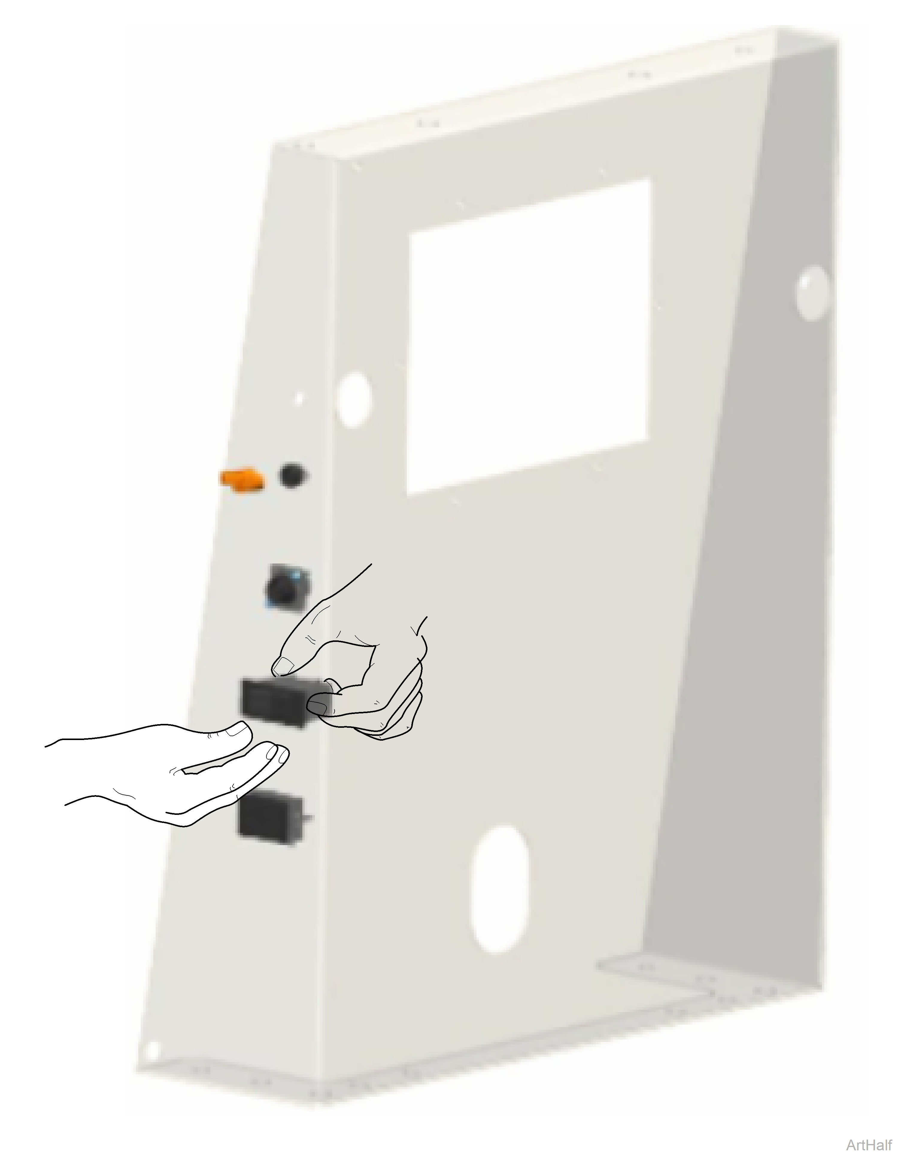
4.Push in on both side of breaker and push forward to pull out of panel.
5.Push in on both sides of breaker. Push breaker into panel and release sides to snap it in to place.
6.Install front cover and restore power.
