PowerVac® P Liquid Evacuation Pump Test and Repair
The PowerVac® Liquid Evacuation Pump Accessory provides additional security for an extremely busy practice. Easily installed as OEM or as a later accessory, the Liquid Evacuation Pump ensures that the PowerVac® operates without interruption by automatically draining the separation tank periodically throughout the day.
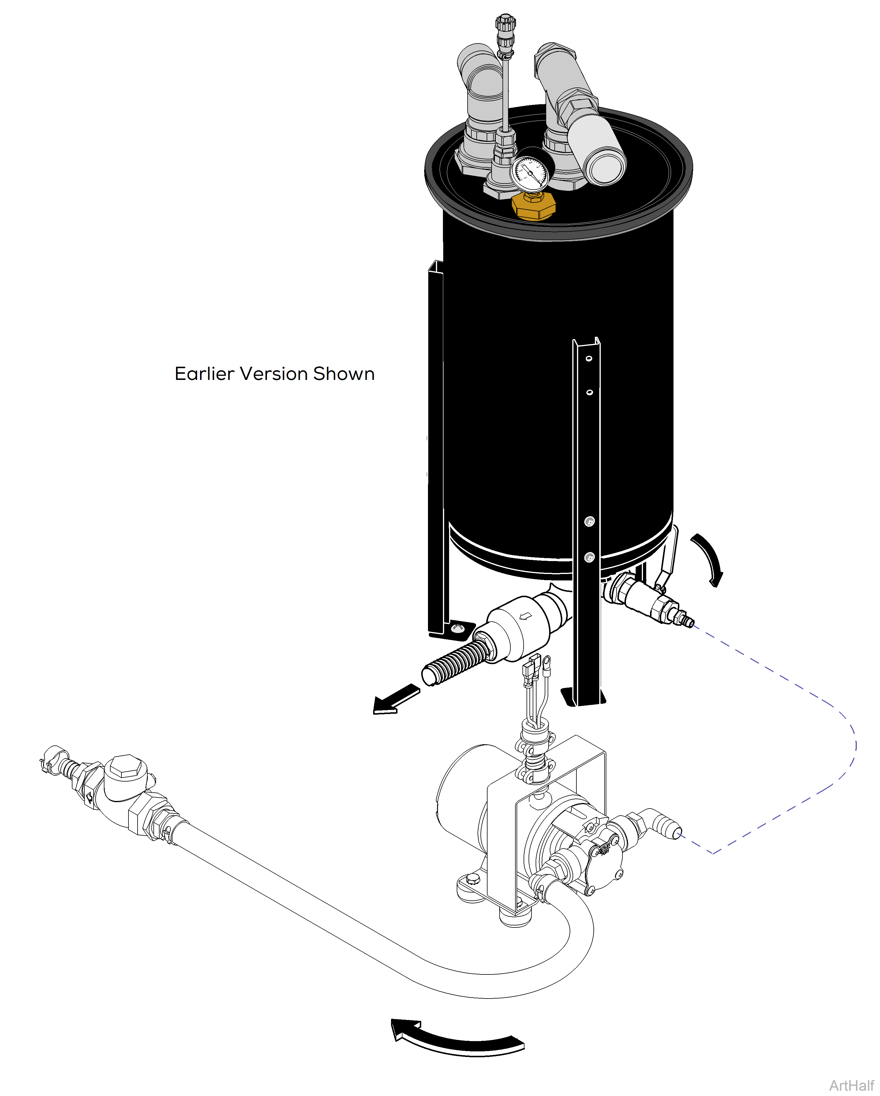
Earlier versions had Three Reed Switch Floats. The middle float was for the Liquid Evac Pump Option. If you have a Liquid Evac Pump connected to the PowerVac® you must replace float with a Three Reed Switch Float Assembly. If there is no Evac Pump Connected to the PowerVac®, you can replace the float with a Two Reed Switch Float Assembly.
When testing components with power on, use care to prevent electrical shock.
All Electrical leads are not shown for the purpose of clarity.
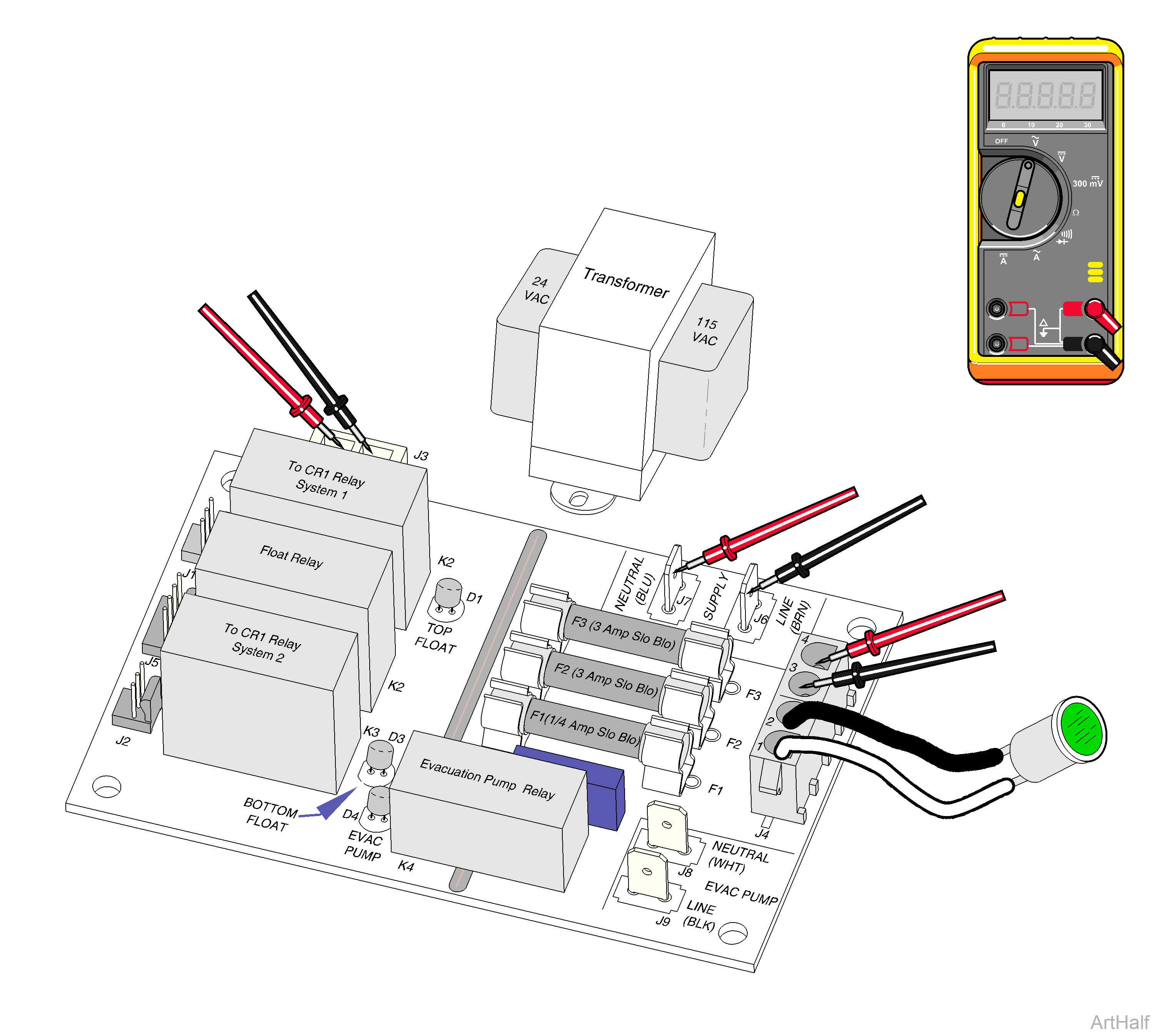
1.With power on, 115 VAC is present at J6 and J7.
If 115 VAC is not present, check main supply power.
2.115 VAC should be present at plug connector 4 (Blk wire) and 3 (white wire) to Transformer.
If 115 VAC is not present, check fuse F1 and F3 and replace if necessary. If F1 and F3 fuses are good, replace PC Board.
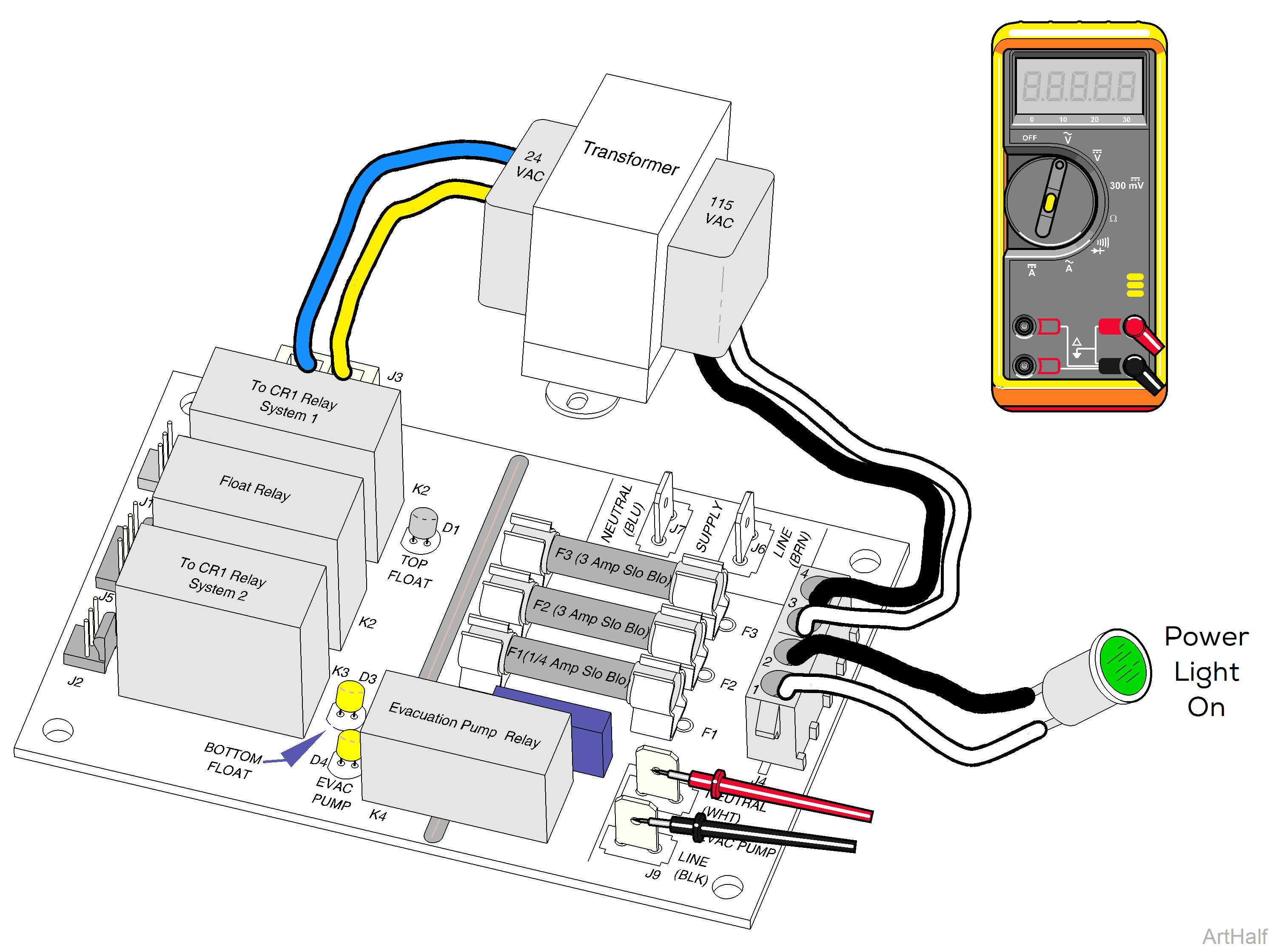
3.115 VAC should be present at plug connector 1 (Blk wire) and 2 (white wire) to Power On Light. Light should be on.
If 115 VAC is not present, check fuse F1 and F3 and replace if necessary. If 115 VAC is present but light is not on, replace light. If F1 and F3 fuses and light are good, replace PC Board.
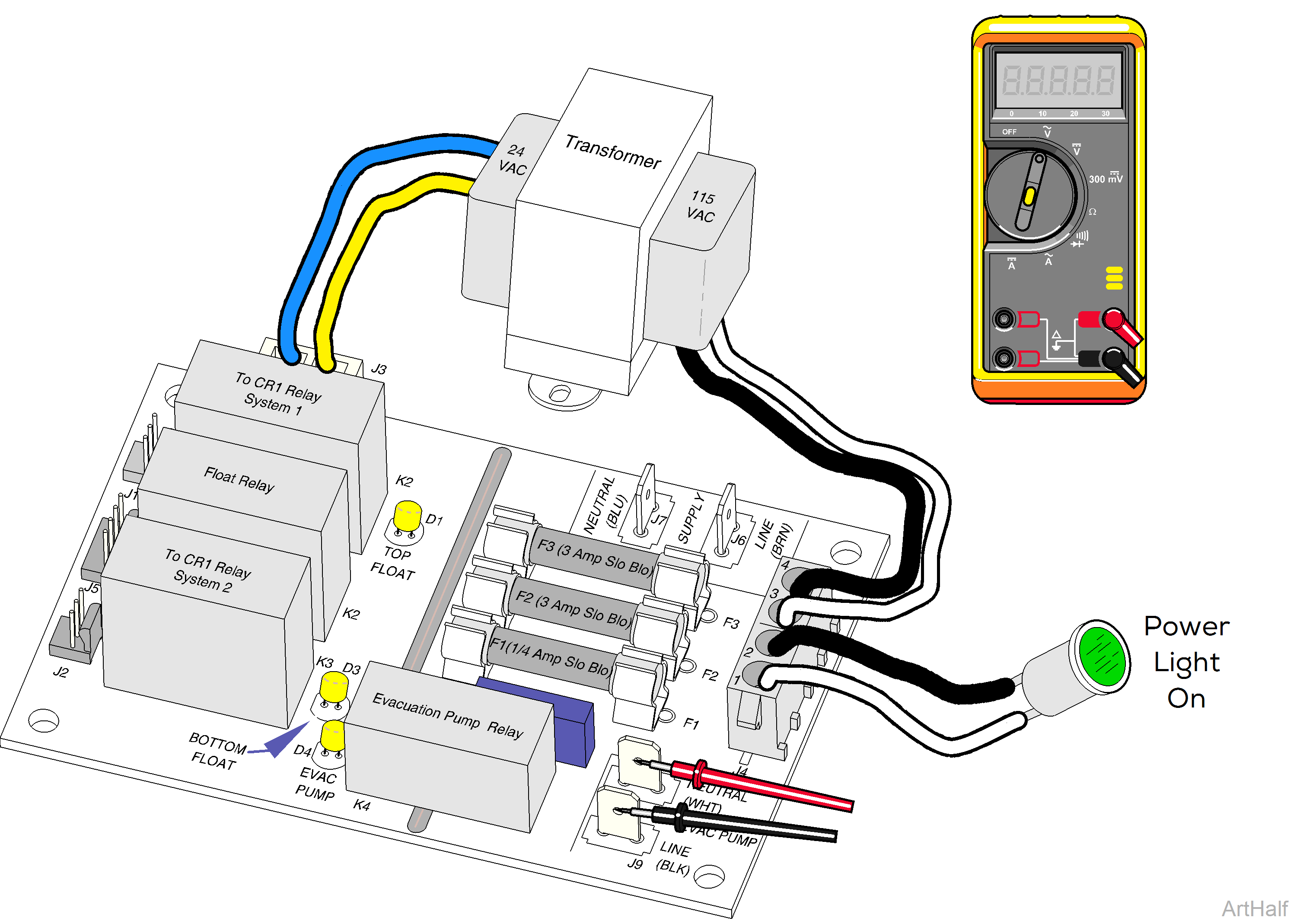
4.24 VAC should be present at J3 plug connector 1 (yellow wire) and 2 (blue wire) from Transformer.
If 24 VAC is not present replace Transformer.
LED's D3 and D4 will cycle On and Off as the Bottom and Middle Float Controls open and close with the level of the fluid.
When D4 is On, the contacts in the Evac. Relay (K4) close and power will be present at J8 and J9 to run the Evac. pump.
1.When D3 and D4 LED's are On 115 VAC should be present at J8 and J9. If 115 VAC is not present, check Fuse F2. If F2 Fuse is good, replace PC Board.
When all three LED's (D1, D3, D4) are on, it indicates the Separator Tank is full of liquid.
D4 indicates the Evacuation Pump Relay coil (K4) is energized, closing its contacts and supplying 115 VAC to terminals J8 and J9 to the Evac. Pump.
The Vacuum Pump shuts off when the contacts (K1) in the Top Float (D1) are closed.
1.115 VAC should be present at J8 and J9. If 115 VAC is not present, check Fuse F2. If F2 Fuse is good, replace PC Board. If 115 VAC is present, check Evacuation Pump.
A full Separator Tank may be due to an obstruction in the outlet side of the system. Assure nothing is obstructing the flow of the discharge from the tank and Evac. Pump during operation.
The motor has a thermal protection that will open, removing power to the motor should it overheat. Ambient temperature around the pump should not exceed 104°F (40°C).
1. If pump motor is running but not pumping fluid:
a. Turn power off to Evac. Pump.
b.Check for restrictions / obstruction in the lines connected to the pump and remove obstacles.
c.Remove cover plate (four screws) and check impeller for obstructions or wear. Replace if necessary.
2.If pump motor is not running, but has 115 VAC supplied to it (PC Board, J8 and J9), check thermal protector.
a.Turn power Off and wait 15 minutes to allow motor to cool and thermal protector to reset.
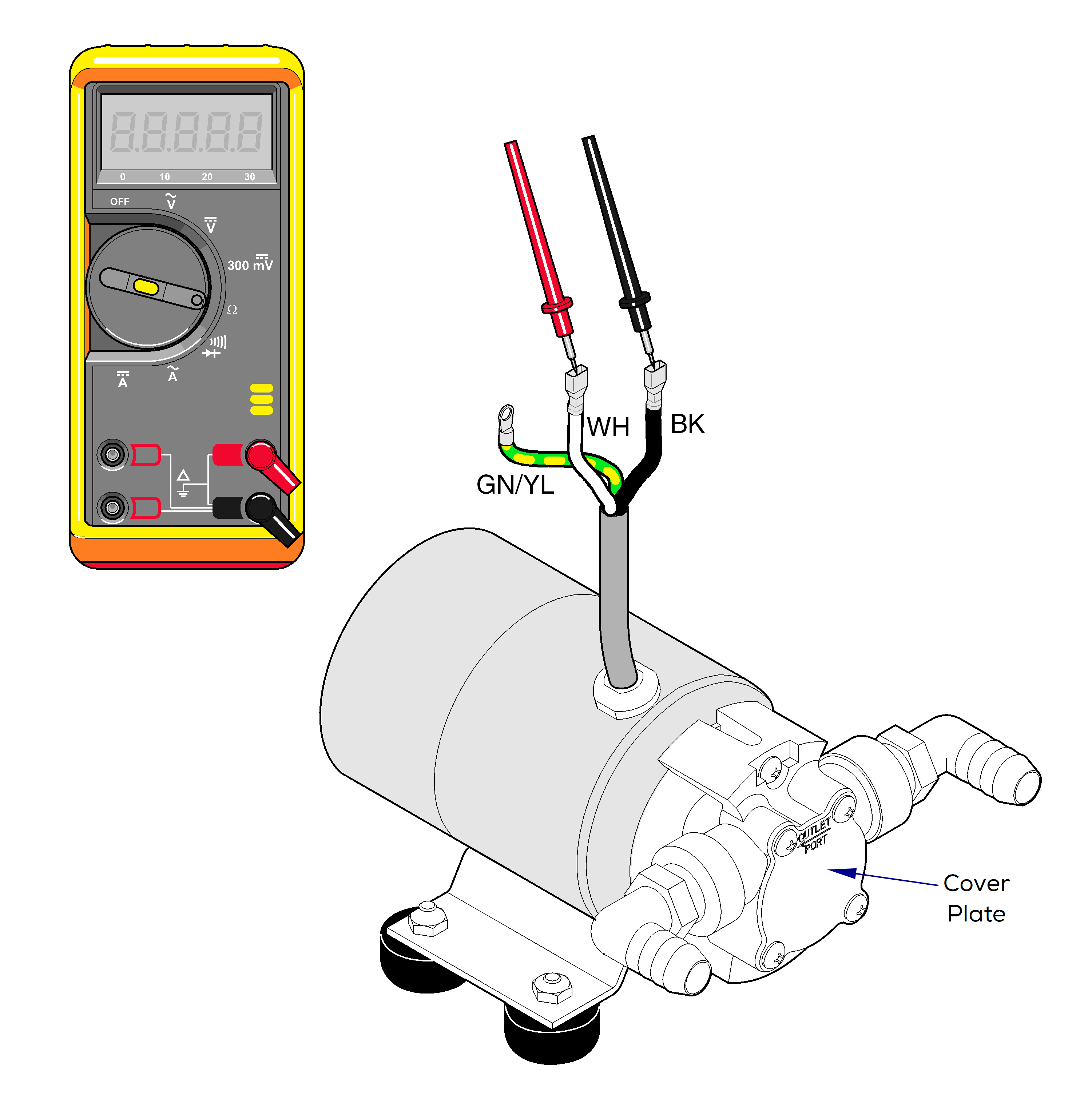
b.Disconnect Black and White motor leads from terminals J8 and J9 on the Evac. Pump PC Board.
c.Set VOM to Ohms Ω. Place meter probes on the White and Black motor leads and check continuity.
| Meter Reading | Status | Required Action |
|---|---|---|
| OL |

|
Winding or Thermal Protector (TP) stays open. Replace Motor Pump |
| Continuity checks OK (20 to 30 ohms, cold reading) |

|
Thermal protector is closed. Winding is within ohms range. Motor is ok. |
