Midmark® Smart Air Compressor Low Voltage - Control Circuit Test and Repair
When testing components with power on, use care to prevent electrical shock.
 Serial Number Range: V2200 thru V2947503
|
Model |
P21-050 | P22-050 | P32-050 | P52-050 | P72-050 |
| Serial Number | V2200 thru V2947503 | V2200 thru V2947503 | V2200 thru V2947503 | V2200 thru V2947503 | V2200 thru V2947503 |
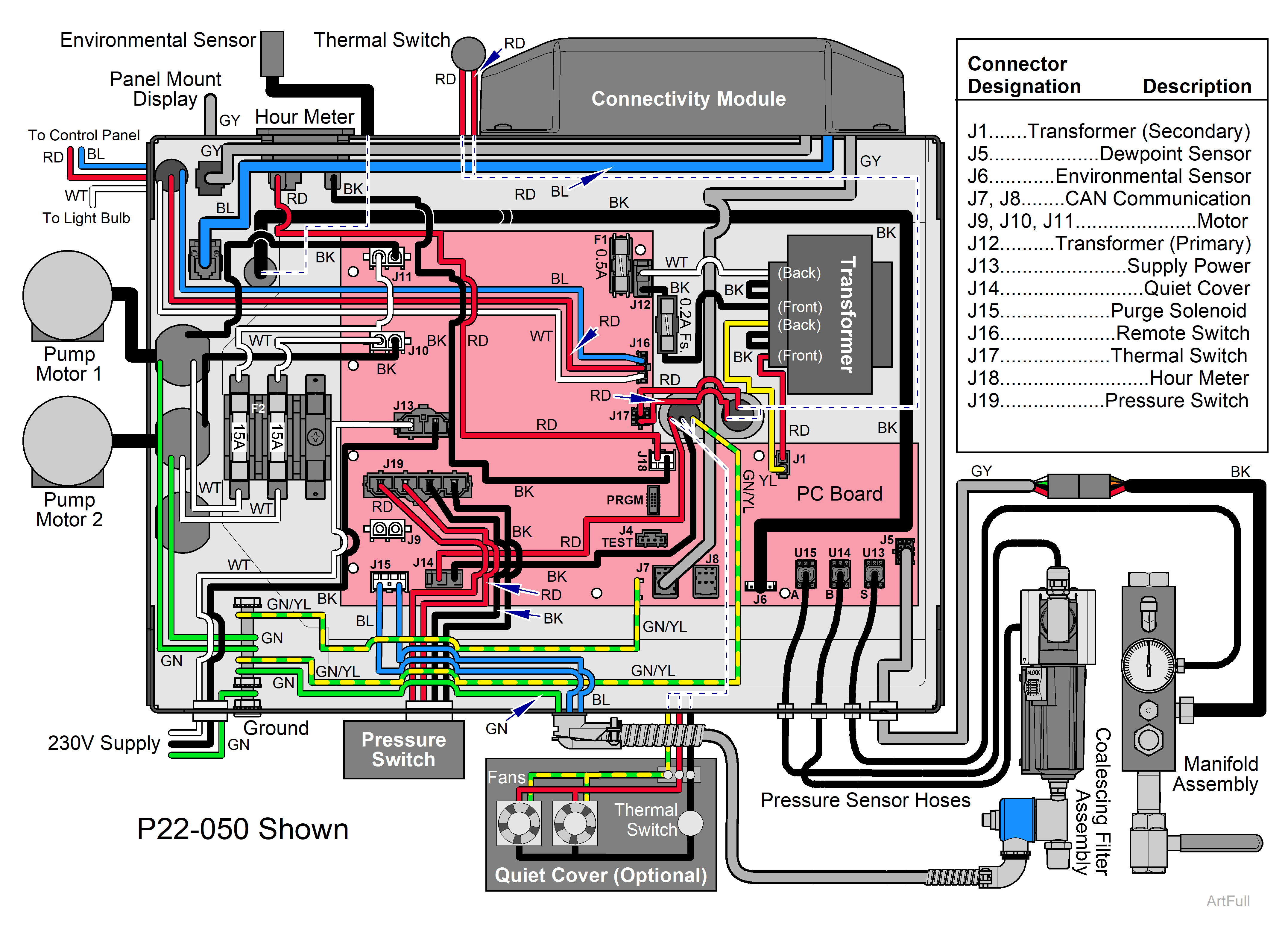
1.Remove electrical box cover. Check for broken or loose wiring. Refer to: Electrical Box Cover
2.Check high voltage on J12. Set meter to V. Place meter probes on black and white wires. Verify reading is 230V (115V for P21 models).
3.Check Low Voltage from transformer to low voltage wires on J1. Place meter probes on Yellow and Red wires. Verify reading is 24 volts.
4.Check high voltage incoming to box at J13.
5.Check Fuse F1 on board and in-line transformer fuse. Replace if needed & see if system starts. Refer to: Fuse
6.Bypass the remote switch to verify it is not defective. Disconnect the Red, White, and Blue wires from the remote switch. Connect the Blue and Red wires together. If the compressor runs (18 second delay), then replace remote wall switch or wiring.
|
Meter Required |
Status |
Required Action |
|---|---|---|
|
High Voltage ≤ Line Voltage |

|
Check incoming power |
|
Low Voltage ≤ 24 Volts |
|
Replace Transformer |
|
High Voltage = Line Voltage |

|
Check Fuse F1 |
|
Low Voltage = 24 Volts |
|
Transformer OK |
Serial Number Range: V2947504 thru Present
|
Model |
P21-050 | P22-050 | P32-050 | P52-050 | P72-050 |
| Serial Number | V2947504 thru Present | V2947504 thru Present | V2947504 thru Present | V2947504 thru Present | V2947504 thru Present |
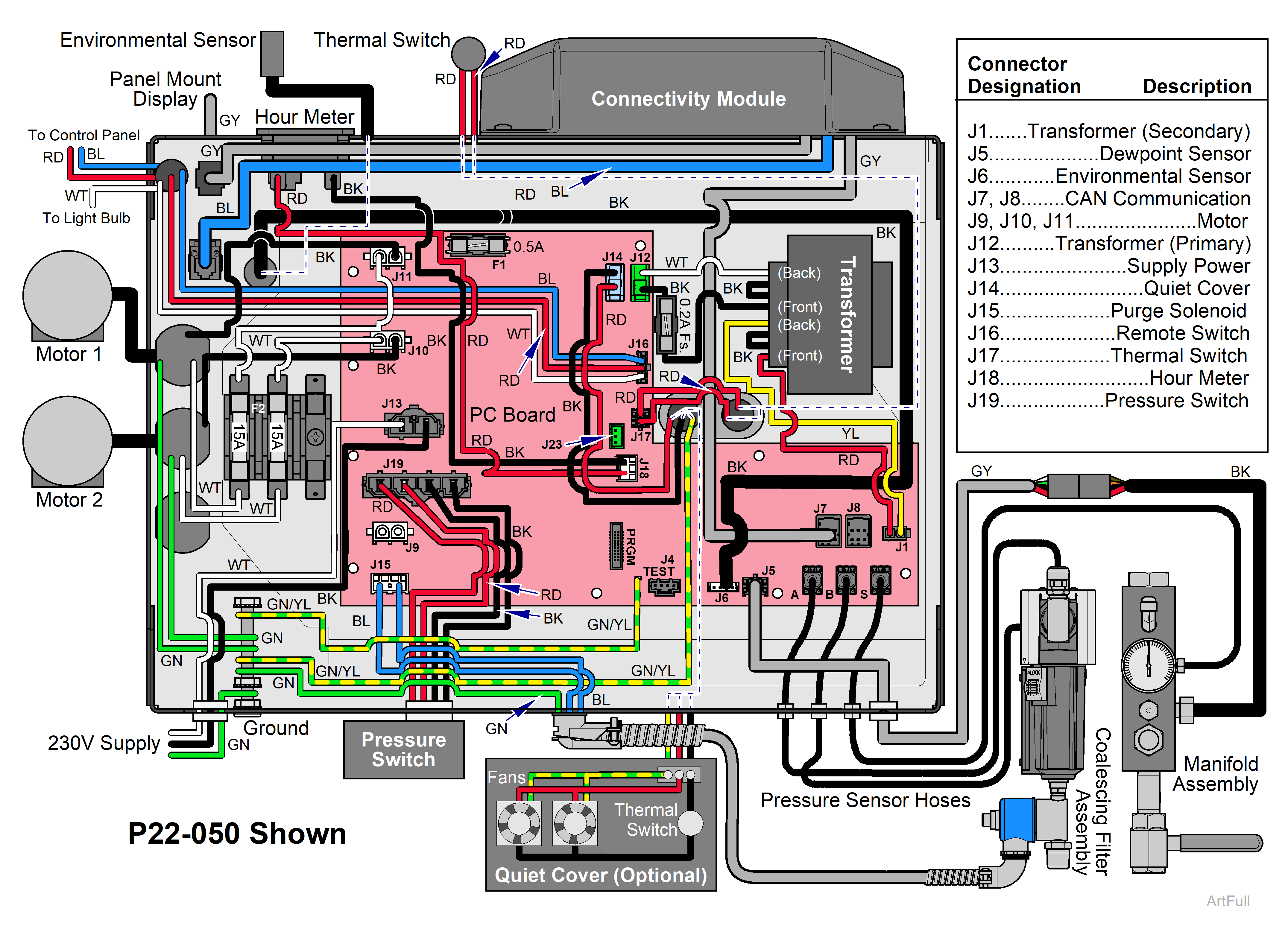
1.Remove electrical box cover. Inspect for loose, broken, or disconnected wiring. Refer to: Electrical Box Cover
2.Check mains voltage at J13 (power into PCB). Set meter to AC volts. Place probes on black and white wires at J13. Verify proper input voltage: 230V (P22-050, P32-050, P52-050, P72-050) or 115 VAC (P21-050). If incorrect, stop troubleshooting.
3.Check transformer primary voltage at J12. J12 should output the same mains voltage found at J13. Confirms the transformer is being powered. If no power, check fuse F1.
4.Check transformer secondary voltage at J1. Place meter probes on yellow and red wires at J1. Verify 24 Volts. If missing, transformer or wiring is faulty.
5.Check PCB DC power LEDs.
Verify internal supply LEDs are solid green:
- DS950 = 24 VDC
- DS450 = 15 VDC
- DS470 = 3.3 VDC
If any LED is off, the PCB cannot operate correctly. Replace PCB.
6.Verify controller status LEDs.
- DS20 OK LED should be blinking green (microcontroller running).
- DS21 Error LED should NOT be blinking red (no error condition).
If DS20 is not blinking or DS21 is flashing red, resolve before continuing.
7.Verify safety inputs (remote and thermal). DS720 REMOTE/THERMAL LED should be off. Solid red indicates the remote switch is OFF or the thermal switch is open. If DS720 is red, the compressor will not run. Bypass remote switch if needed.
8.Check pressure logic. If system pressure is below 80 PSI, DS200 PS_SW_EN STATUS LED should be solid green. This indicates the board is issuing the RUN command. If pressure is low but DS200 is not green, check pressure switch or logic input.
9.Verify motor enable output. If all conditions above are satisfied and the motor should be turning on, DS400 MOTOR_STATUS ENABLE LED should be solid green. This indicates output triacs/drivers are energized. If DS200 is green but DS400 is not, there is an output stage or motor safety issue. After a delay of 18 seconds from power up, DS200 should turn green. If DS200 does not turn green, replace PCB.
10.Check motor fuses.
| LED Light | Label | Indicates |
|---|---|---|
| DS20 | OK | Blinking green when operating normally. |
| DS21 | ERROR | Continuous red flashing when there is an error in the system. |
| DS720 | REMOTE/THERMAL ERROR | Solid RED when remote switch open or thermal switch closed. |
| DS200 | PS_SW_EN STATUS | LED turns solid green when sending run command to motor. |
| DS400 | MOTOR_STATUS ENABLE | Triacs are Enabled (Motors should be running). |
| DS450 | 15 VDC | Solid green when 15VDC circuit is functional. |
| DS470 | 3.3 VDC | Solid green when 3.3VDC circuit is functional. |
| DS950 | 24 VDC | Solid green when 24VDC circuit is functional. |
|
Meter Required |
Status |
Required Action |
|---|---|---|
|
High Voltage ≤ Line Voltage |
|
Check incoming power |
|
Low Voltage ≤ 24 Volts |
|
Replace Transformer |
|
High Voltage = Line Voltage |
|
Check Fuse F1 |
|
Low Voltage = 24 Volts |
|
Transformer OK |