224 Exam Chair Diagnostic LEDs and Error Code Troubleshooting
The 224 has five LEDs and a diagnostic switch (S1) located on the Motor Control PC board for diagnostic purposes. There are three modes that use these LEDs; Run Mode, Switch Check Mode, and Error Display Mode. You can switch between these modes by pressing and holding the S1 switch for three seconds.
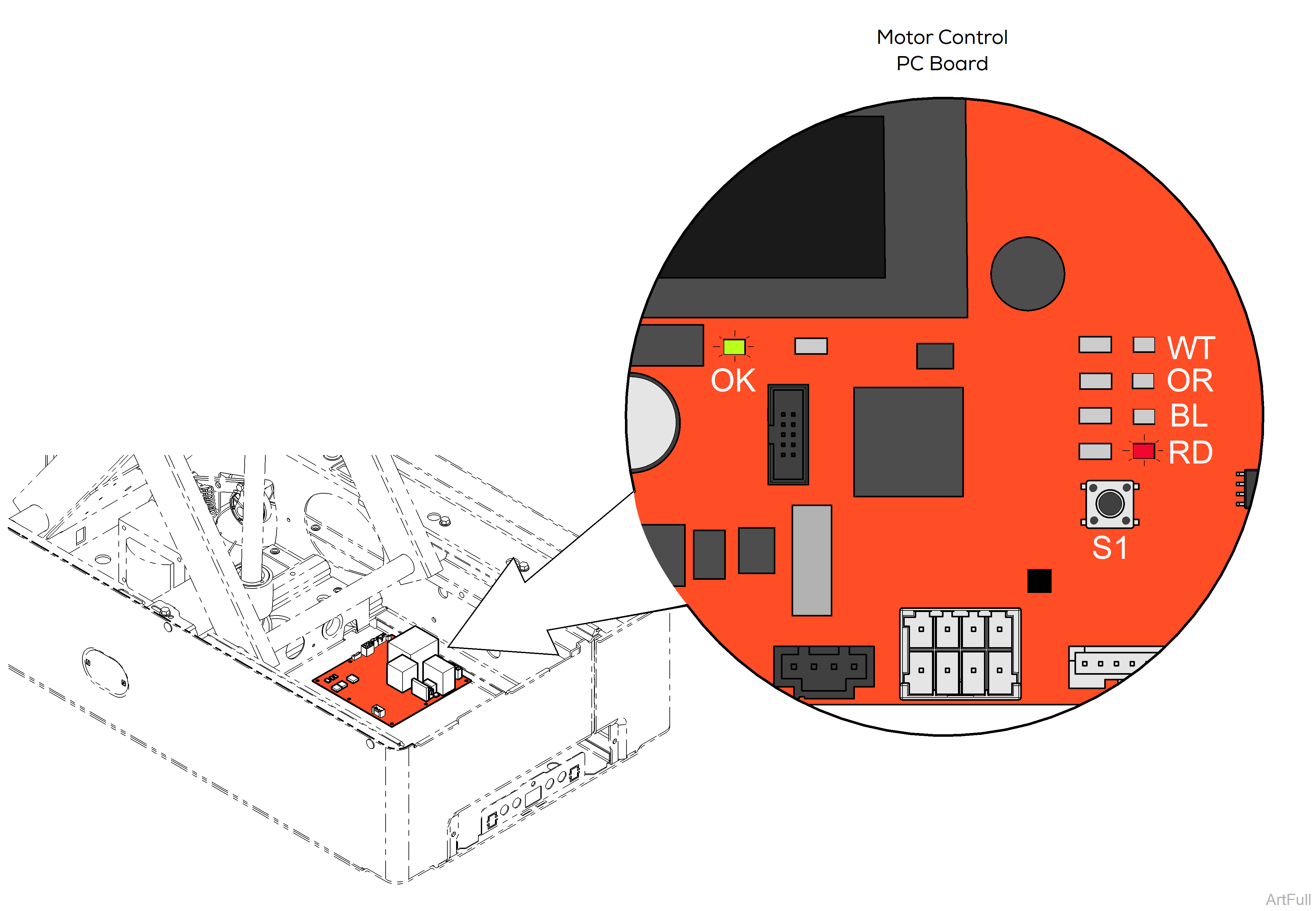
The Run Mode is the default configuration of the system. It is where the other modes revert to if the S1 switch is not pressed for fifteen minutes.
| Activity | Definition |
|---|---|
| Green (OK) LED Flashing | System operating normally. |
| Red (RD) LED Flashing | System has an error. |
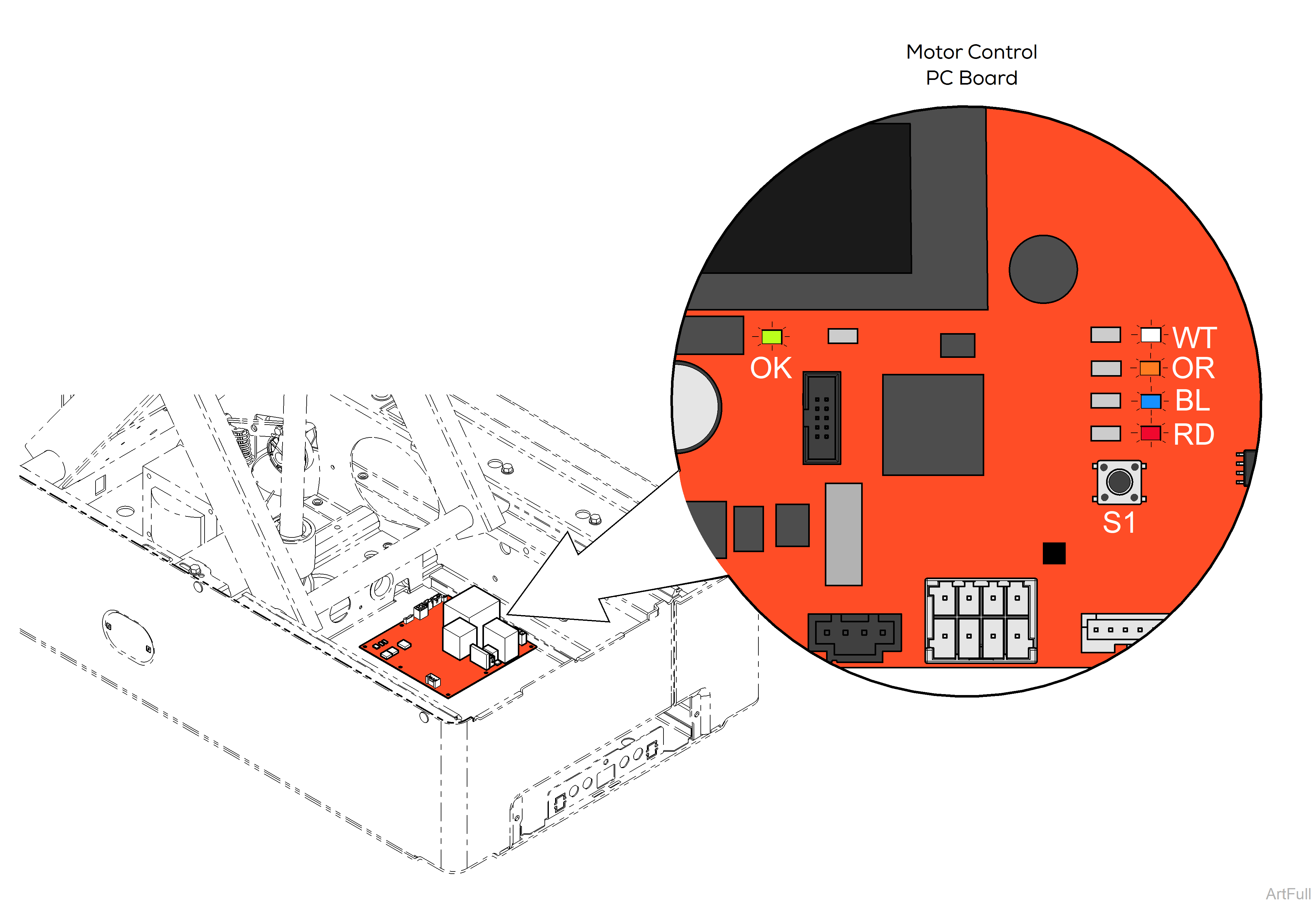
The Switch Check Mode allows for checking the switches without the use of special equipment. To enter the Switch Check Mode, press and hold the diagnostic switch (S1) for three seconds. The Motor Control PC Board will give two short beeps and the majority of the diagnostic LEDs will turn on.
In the Switch Check Mode, activating a limit switch turns off a LED, see table below. Pressing a control switch on the Foot control will elicit a single beep from the Motor Control PC Board. This mode will time out and revert to the Run Mode after fifteen minutes.
| Activity | Definition |
|---|---|
| Green (OK) LED Flashing | System running. |
| White (WT) LED | Not applicable in this mode. |
| Orange (OR) LED Off | Active Sensing Technology™ switch(es) open. |
| Blue (BL) LED Off | Base Up limit switch open. |
| Red (RD) LED Off | Base Down limit switch open. |
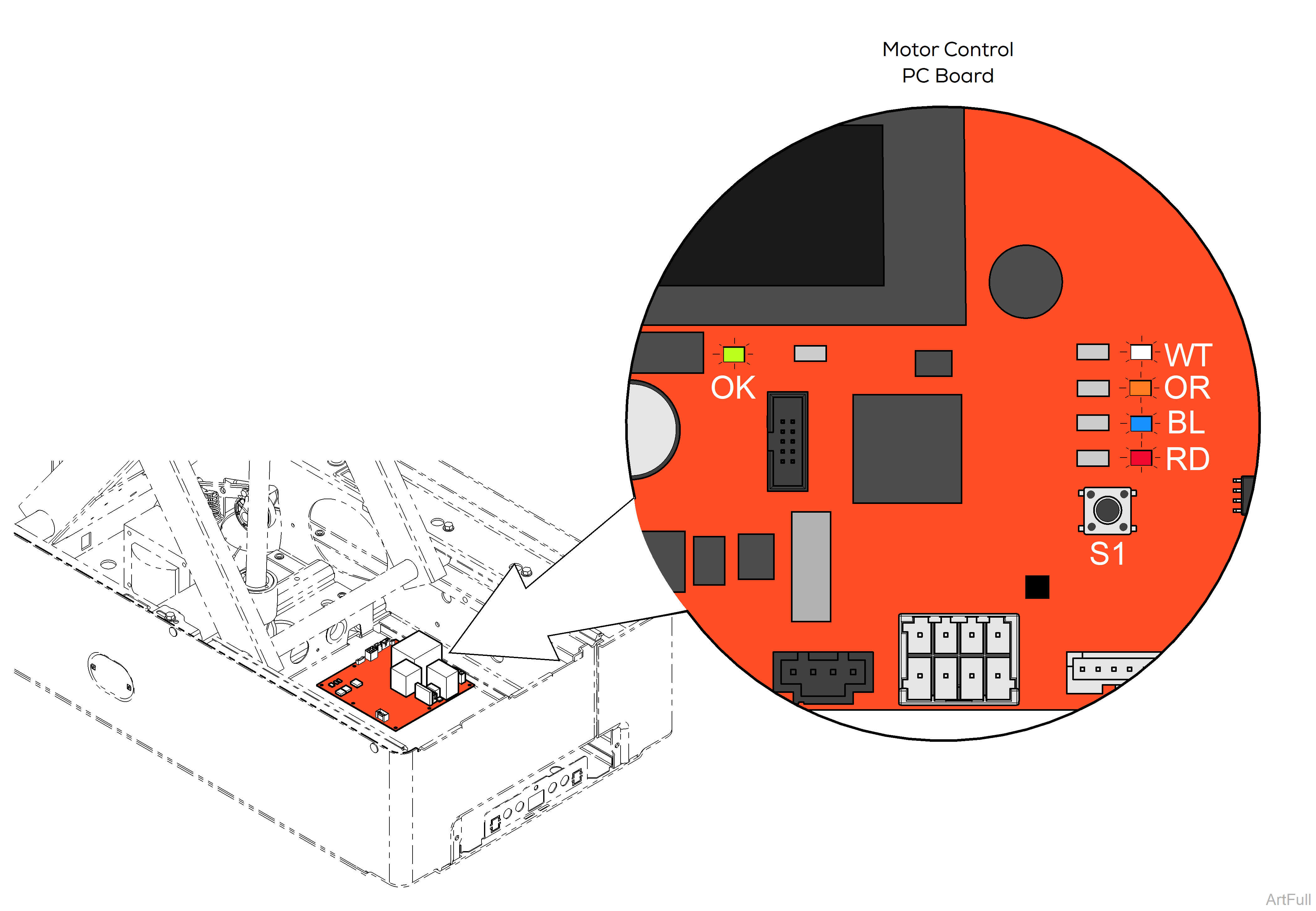
The Error Display mode allows for viewing of both current and past errors detected by the Motor Control PC Board. Errors are detectable by the Motor Control PC Board and these are indicated by the use of LEDs with a last LED (Red) to indicate if the error being displayed is current.
To show the errors: From the Run Mode, press the diagnostic switch (S1) once for three seconds and then press it again for three seconds. The most recent error will be displayed by the LEDs. If no errors have been detected, no LEDs will turn on. Pressing the S1 switch again will display the next most recent error. Repeating switch presses will continue displaying subsequent errors until the error list is complete and the LEDs will all be off. Pressing the S1 switch again will repeat this process.
The LED pattern for each error is in the table below. The LEDs will turn off if a switch is not pressed for fifteen minutes.
Pressing and holding the S1 switch for ten seconds will clear all errors. Two Beeps will occur, one after three seconds and one after ten seconds.
| Activity | Code | Definition |
|---|---|---|
| Green (OK) LED Flashing | N/A | System running. |
| Green (OK) LED Off | N/A | Error Condition |
| Red (RD) LED On | N/A | Current Error |
| White (WT) LED On | 01 | Active Sensing Technology™ and Base Up limit switches open. |
| Orange (OR) LED On | 02 | Base Up and Down limit switches open. |
| White (WT), Orange (OR) LEDs On | 03 | Base Over Current |
| Blue (BL) LED On | 04 | Base Over Voltage |
| White (WT), Blue (BL) LED’s On | 05 | Motor Bus Voltage Low |
| White (WT), Blue (BL) LED’s On | 06 | Motor Bus Voltage High |
| Orange (OR), Blue (BL) LED’s On | 07 | Switches Pressed at Startup |
| White (WT), Orange (OR), Blue (BL) LEDs On | 08 | Motor Bus Fuse (F1) Blown or Overtravel limit switch open. |
| Error Code | Error Definition | Cause | Check | Action |
|---|---|---|---|---|
| 01 | Active Sensing Technology™ and Base Up switch(es) open. | Active Sensing Technology™ activated. | Check if chair came in contact with another object. | Remove object from beneath drawer. |
| Active Sensing Technology™ switch(es). | On Motor Control PC board J1 connection jump white wires for AST switches. Refer to: Base Function Fuses and Connections | Replace defective switch(es). Refer to: Active Sensing Technology™ Switches | ||
| Loose or faulty Active Sensing Technology™ switch wire connections. | Check wires connections between Motor Control PC board and AST switches. Refer to: Base Function Fuses and Connections | Secure or replace loose wire connections. Refer to: Active Sensing Technology™ Switches | ||
| 02 | Base Up and Down limit switch(es) open. | Base up limit switch. | On Motor Control PC board J1 connection jump white wires for Base up limit switch. Refer to: Base Function Fuses and Connections | Replace defective limit switch. Refer to: Base Function Components |
| Loose or faulty Base up limit switch wire connections. | Check wires connections between Motor Control PC board and limit switch. Refer to: Base Function Fuses and Connections | Secure or replace loose wire connections. | ||
| Base down limit switch. | On Motor Control PC board J1 connection jump black wires for Base down limit switch. Refer to: Base Function Fuses and Connections | Replace defective limit switch. Refer to: Base Function Components | ||
| Loose or faulty Base down limit switch wire connections. | Check wires connections between Motor Control PC board and limit switch. Refer to: Base Function Fuses and Connections | Secure or replace loose wire connections. | ||
| 03 | Base Over Current | Patient weight exceeded 500 lbs. | Check if patient weight exceeded the 500 lb. weight limit. | Inform staff that maximum patient weight is 500 lbs. |
| Mechanical binding. | Check actuator mounts and scissors / slides for damage. | Report any damage to Midmark Technical Service. | ||
| 04 | Base Over Voltage | Hardware sensed too much voltage across Base actuator motor. | Base actuator motor. | Replace Base actuator motor. If the issue persist, replace Motor Control PC board. |
| Motor Control PC board. | ||||
| 05 | Motor Bus Voltage Low | Low supply voltage. | Check facility supply voltage. | Contact electrician to modify voltage if necessary. |
| 06 | Motor Bus Voltage High | High supply voltage. | Check facility supply voltage. | Contact electrician to modify voltage if necessary. |
| 07 | Switches Pressed at Startup | User input activated at power-up. | A control button was pressed during power-up. | Assure push-button is not pressed during power-up. |
| Damage to Control cord. | Check Foot control cord for damage. Perform Foot control cord test. Refer to: Foot Control Cord Test | Replace faulty Foot control cord. | ||
| Faulty Control. | If possible, use known working Foot control from another like chair. | Replace faulty Foot control. | ||
| 08 | Motor Bus Fuse (F1) Blown | Motor Control PC board fuse blown. | Test F1 fuse. Refer to: Base Function Fuses and Connections | Replace blown fuse. |
| Overtravel limit switch. | Overtravel limit switch could be activated. Verify Overtravel limit switch is clear of debris. | Inspect Overtravel limit switch. Refer to: Base Function Components | ||
| On Motor Control PC board J3 connection jump orange wires for overtravel limit switch. Refer to: Base Function Fuses and Connections | Replace defective limit switch. Refer to: Base Function Components | |||
| Loose or faulty overtravel limit switch wire connections. | Check wires connections between Motor Control PC board and limit switch. Refer to: Base Function Fuses and Connections | Secure or replace loose wire connections. |
