224 Exam Chair Access Procedures
Always disconnect power to chair before removing covers or performing any service procedures.
Risk of electrical shock. Always disconnect chair power for three minutes, allowing capacitance to dissipate prior to servicing the Motor Control PC board.
Some steps may not apply if chair is in a position where PC board cover can be removed.
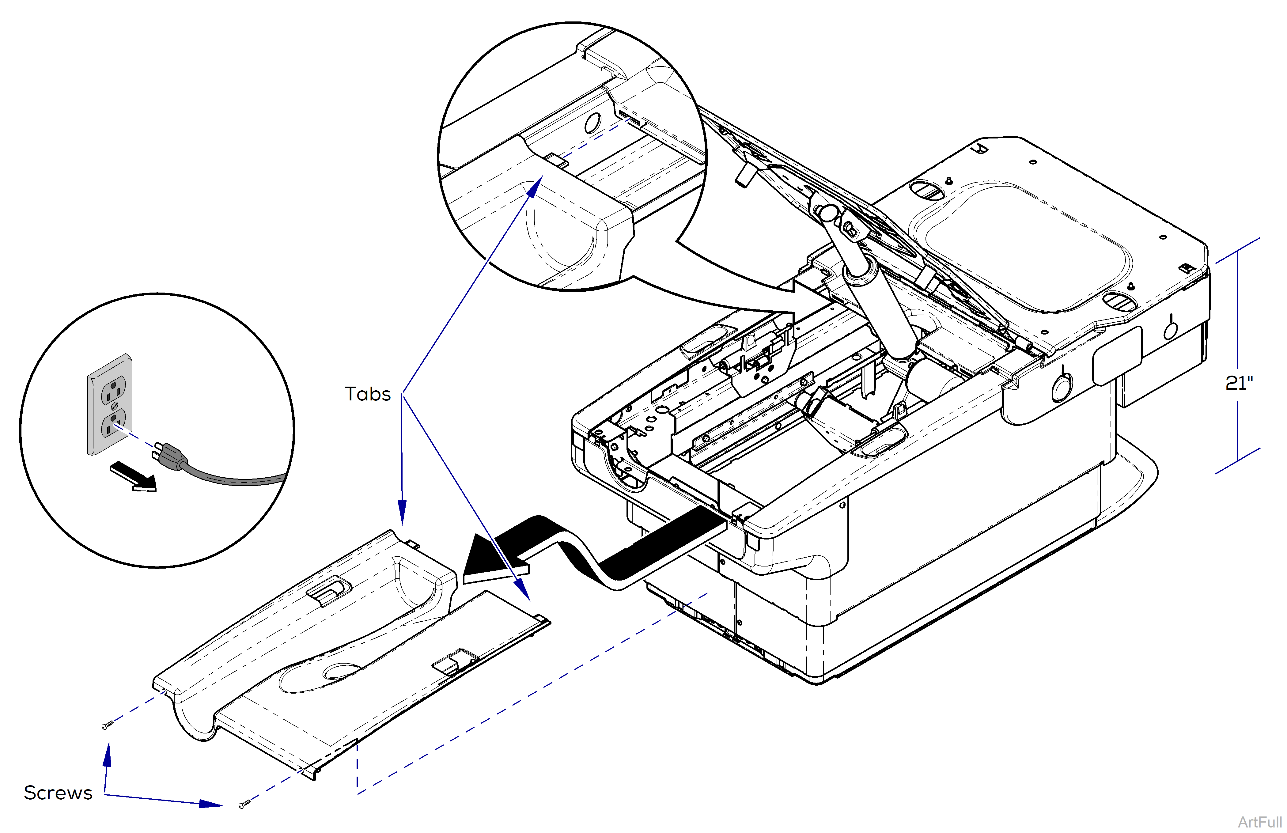
1.Position chair to approximately 21” from the top of chair frame to floor.
2.Unplug chair.
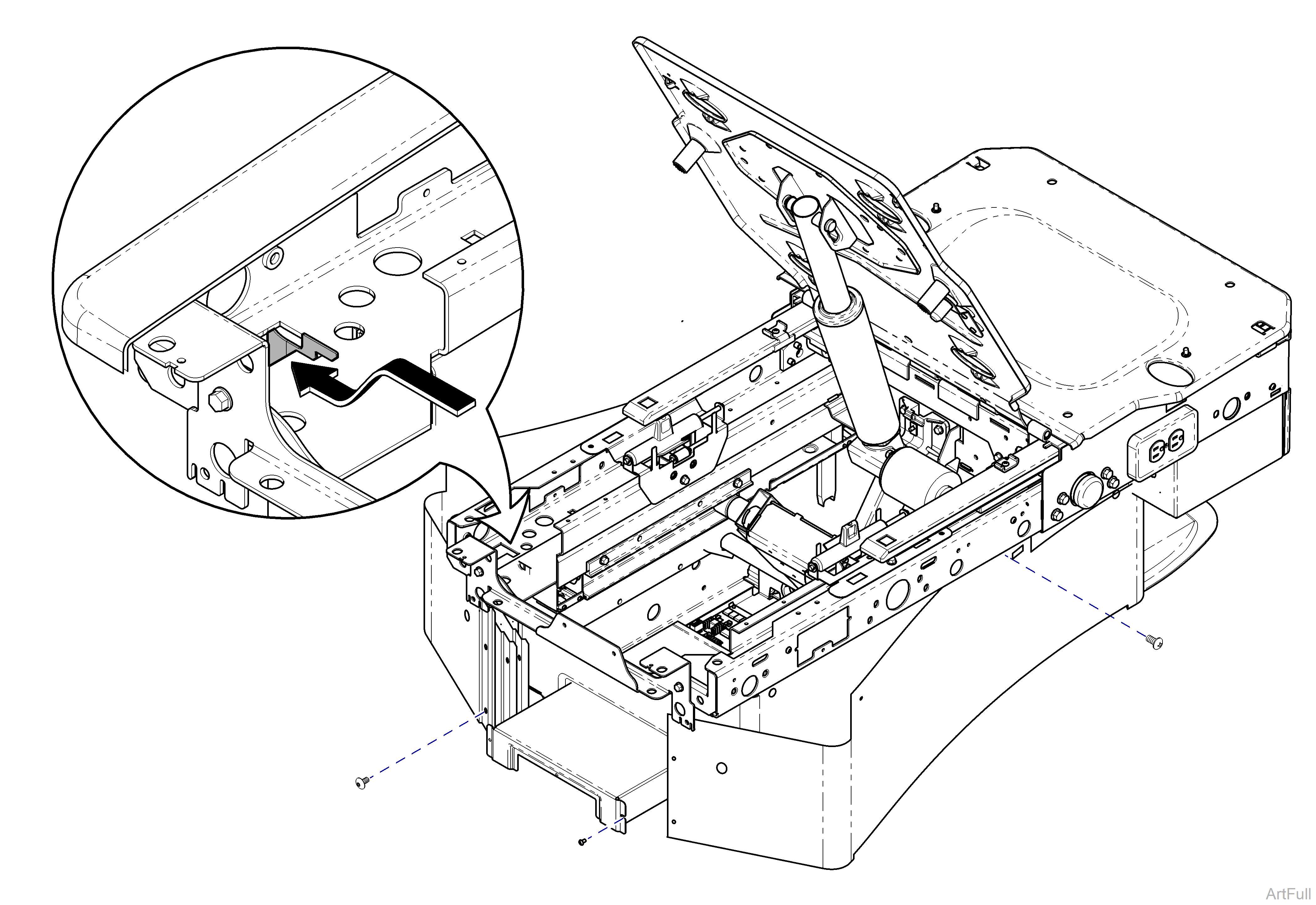
3.Remove two screws from back of Top Cover.
4.Pull cover toward head end to disengage tabs, then lift up to remove cover.
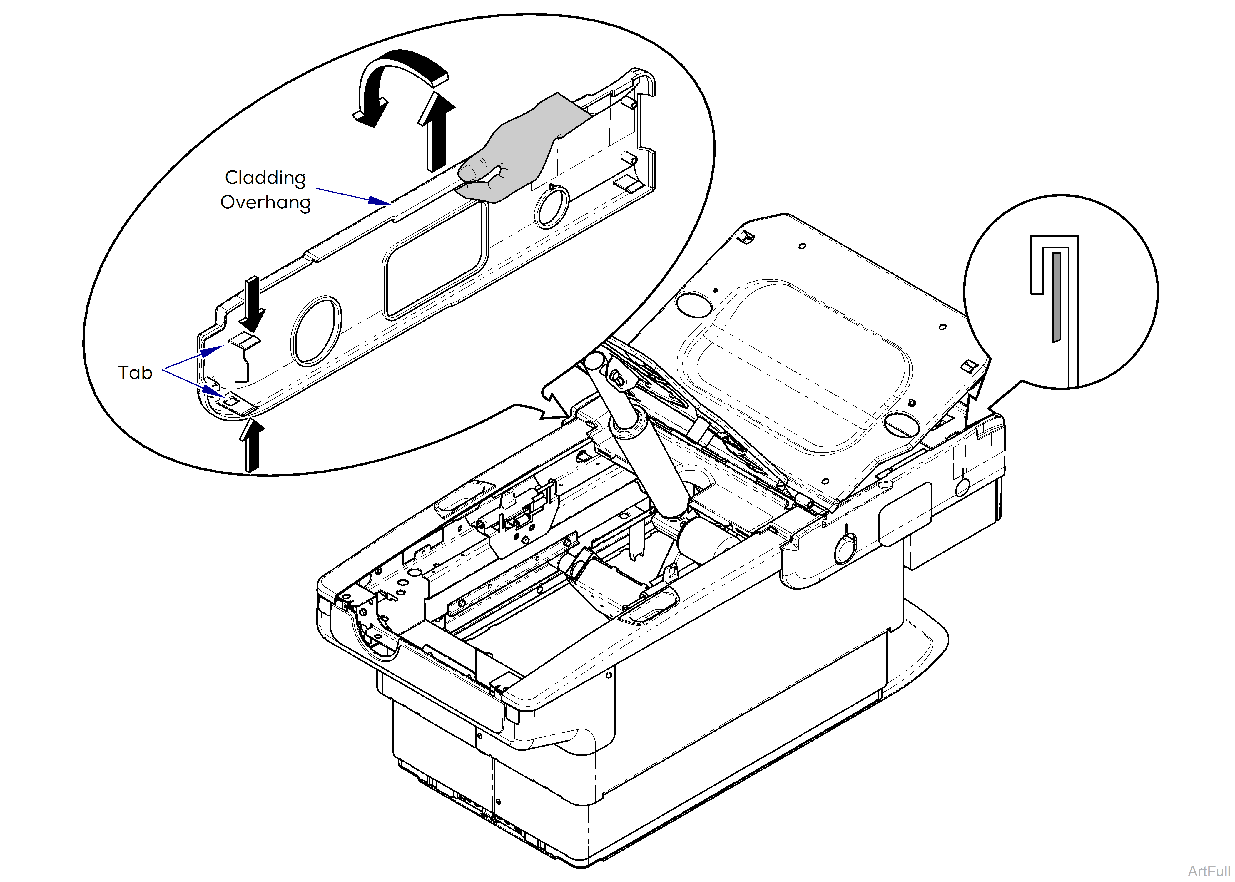
Remove all accessories (ex. chair arms) before performing this procedure.
1.Locate tabs inside at center of chair with footrest extended. Push down on top tab and up on bottom tab. Pull cladding away from chair.
2.Pull up on Cladding overhang and remove.
3.Repeat process for opposite side.
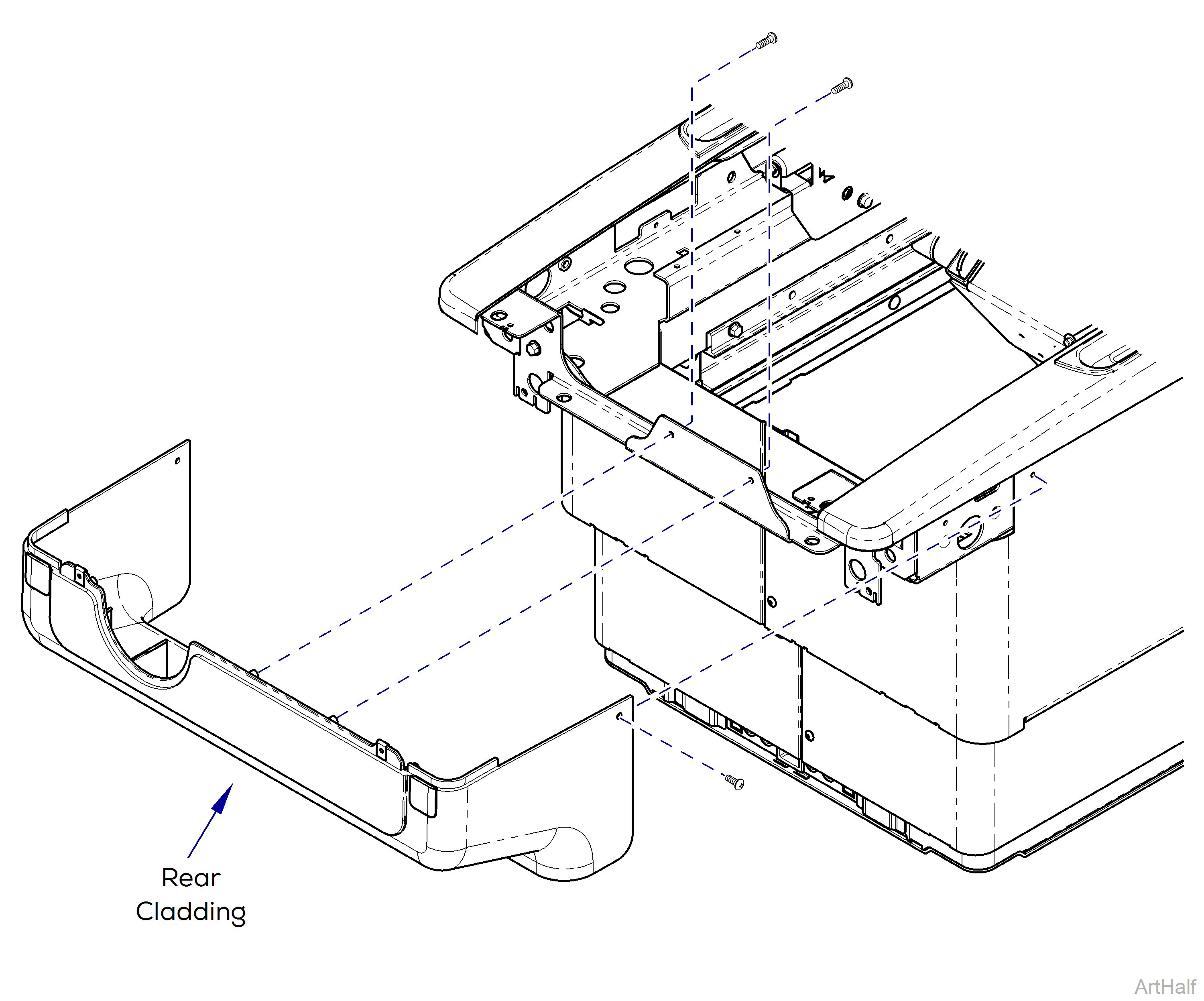
1.Remove two screws from outside corners of Rear Cladding.
2.Remove two screws from inside center of Rear Cladding.
3.Remove Rear Cladding.
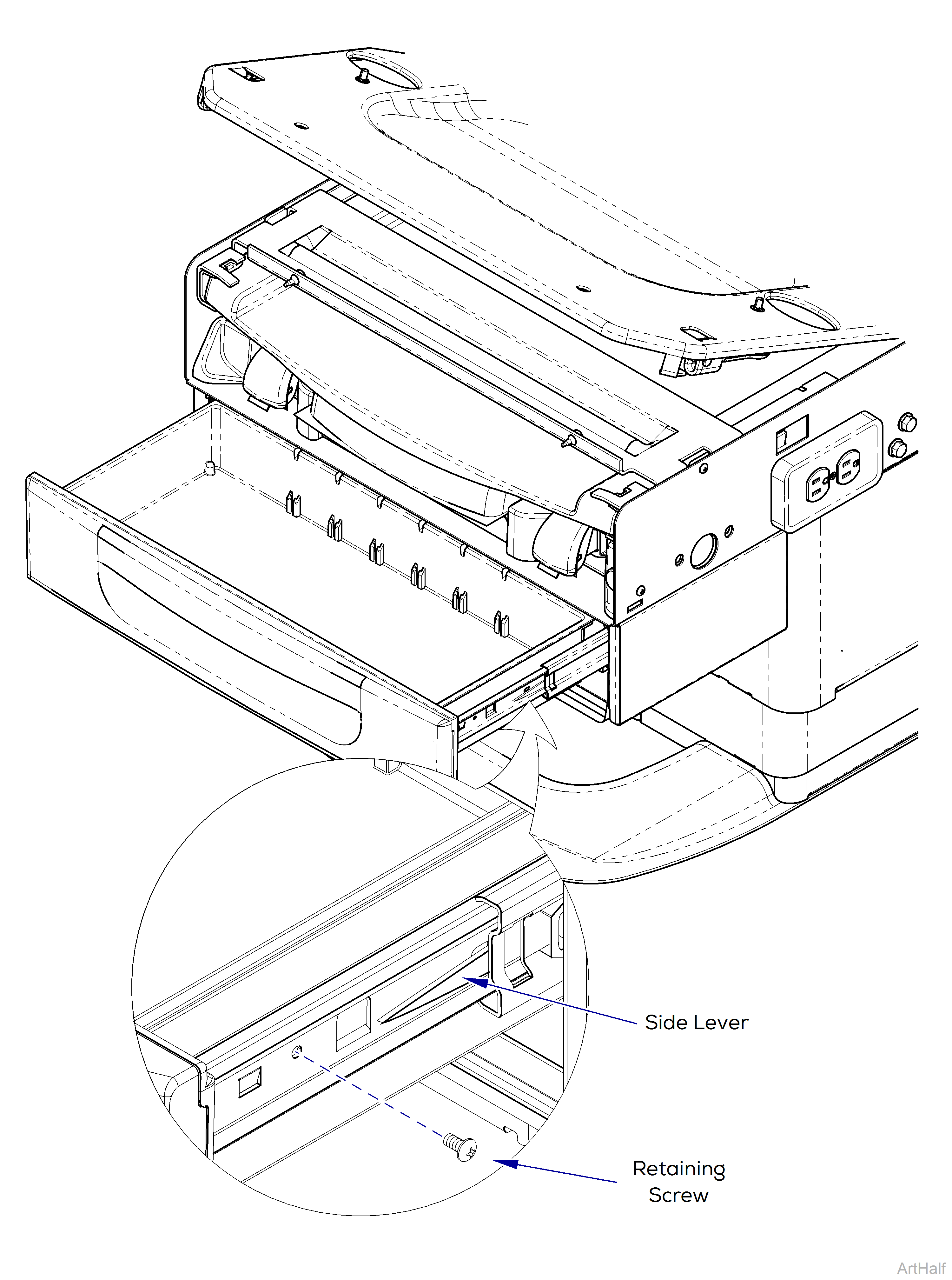
Side levers are clear plastic
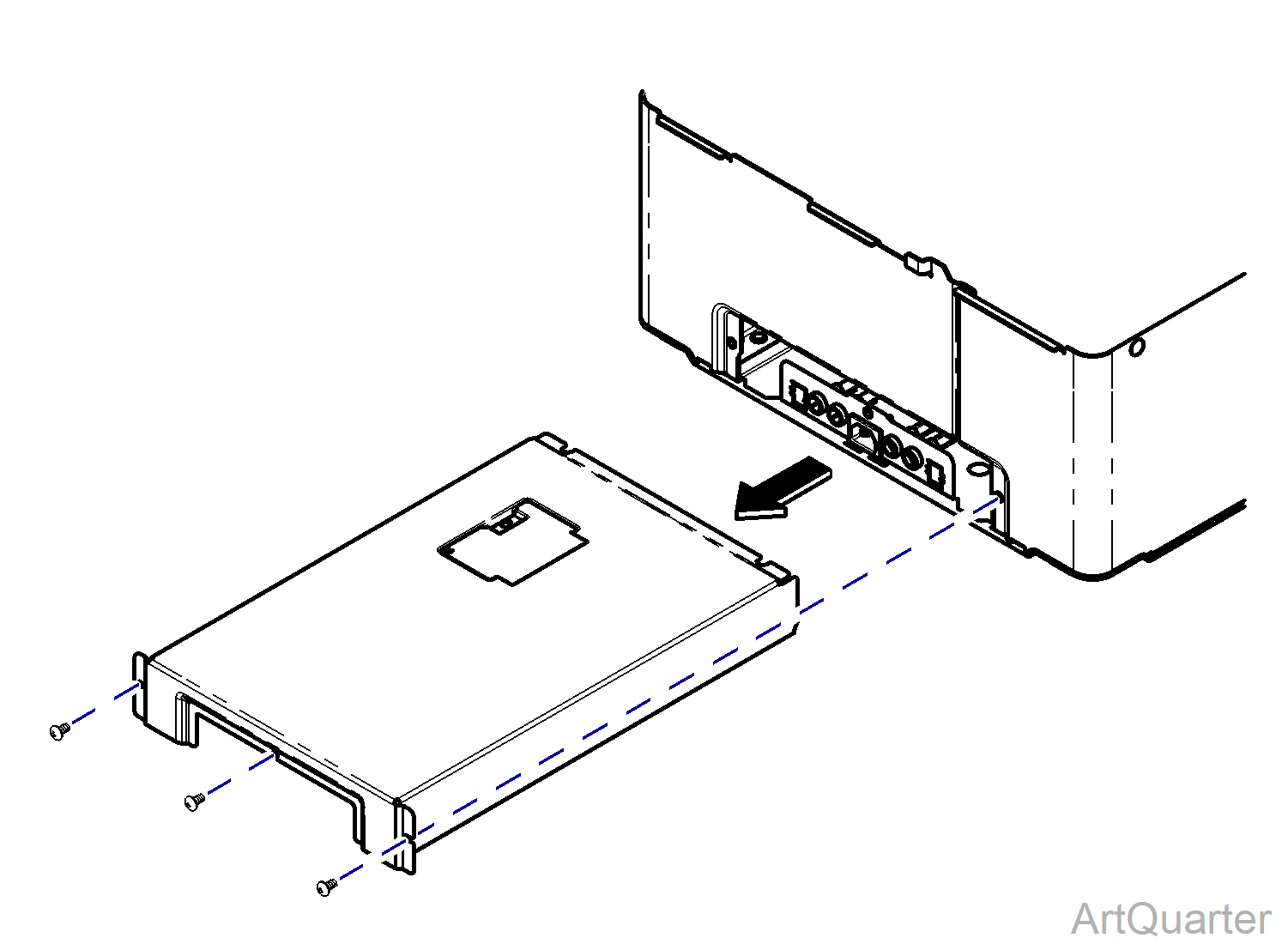
1.Remove Retaining Screw. Located on one side only.
2.Push LH side lever up and RH side lever down.
3.Remove drawer by pulling straight out.
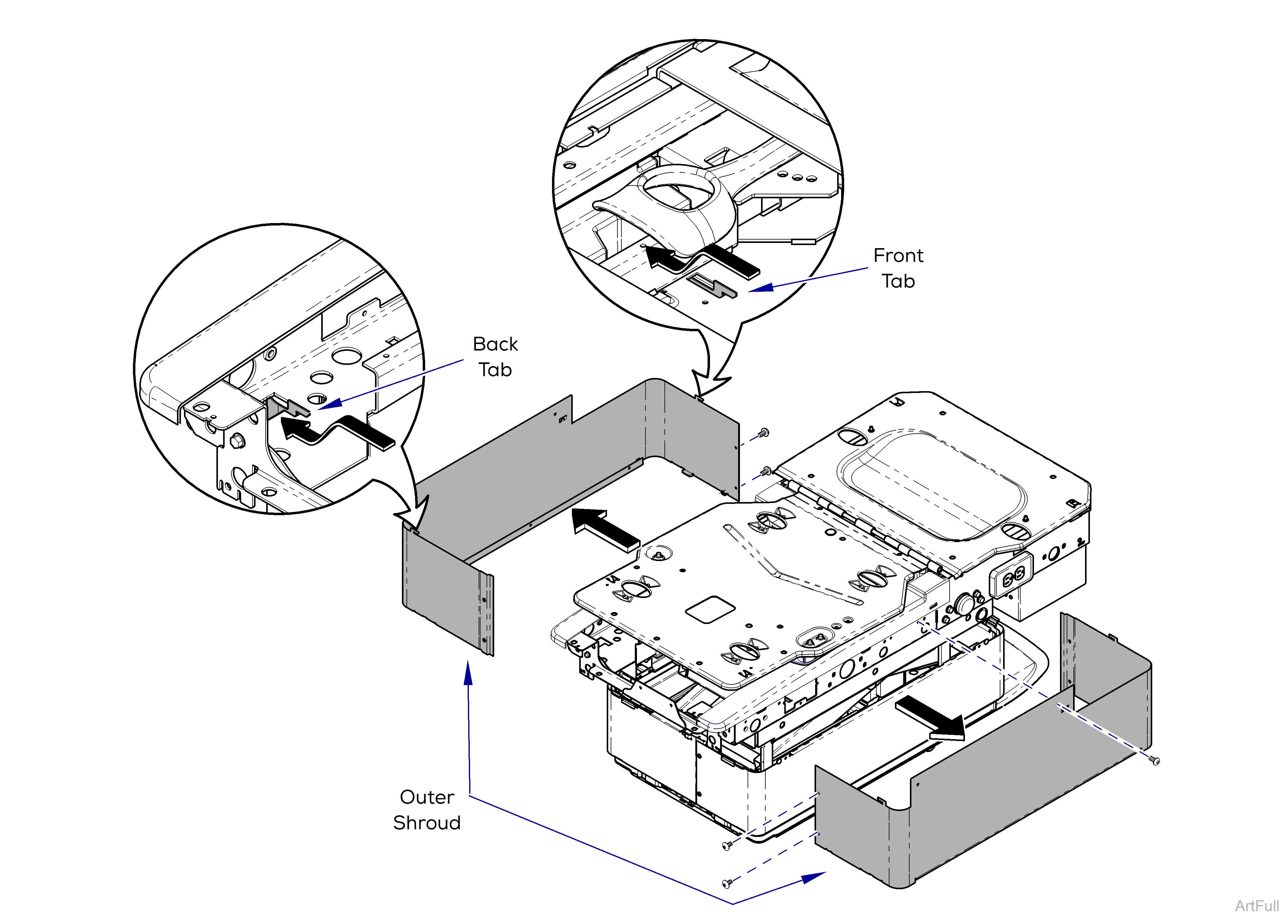
If the chair is at a height where the inner shrouds are being lifted/supported by the outer shroud, care must be taken to secure the inner shrouds while removing the outer shrouds.
Removal
1.Remove screws from head-end and foot-end of Outer Shrouds.
2.Remove screw from side of Outer Shrouds.
3.Pull Outer Shroud away from chair and lower the tabs out of slots.
4.Remove Outer Shroud and repeat on opposite side.
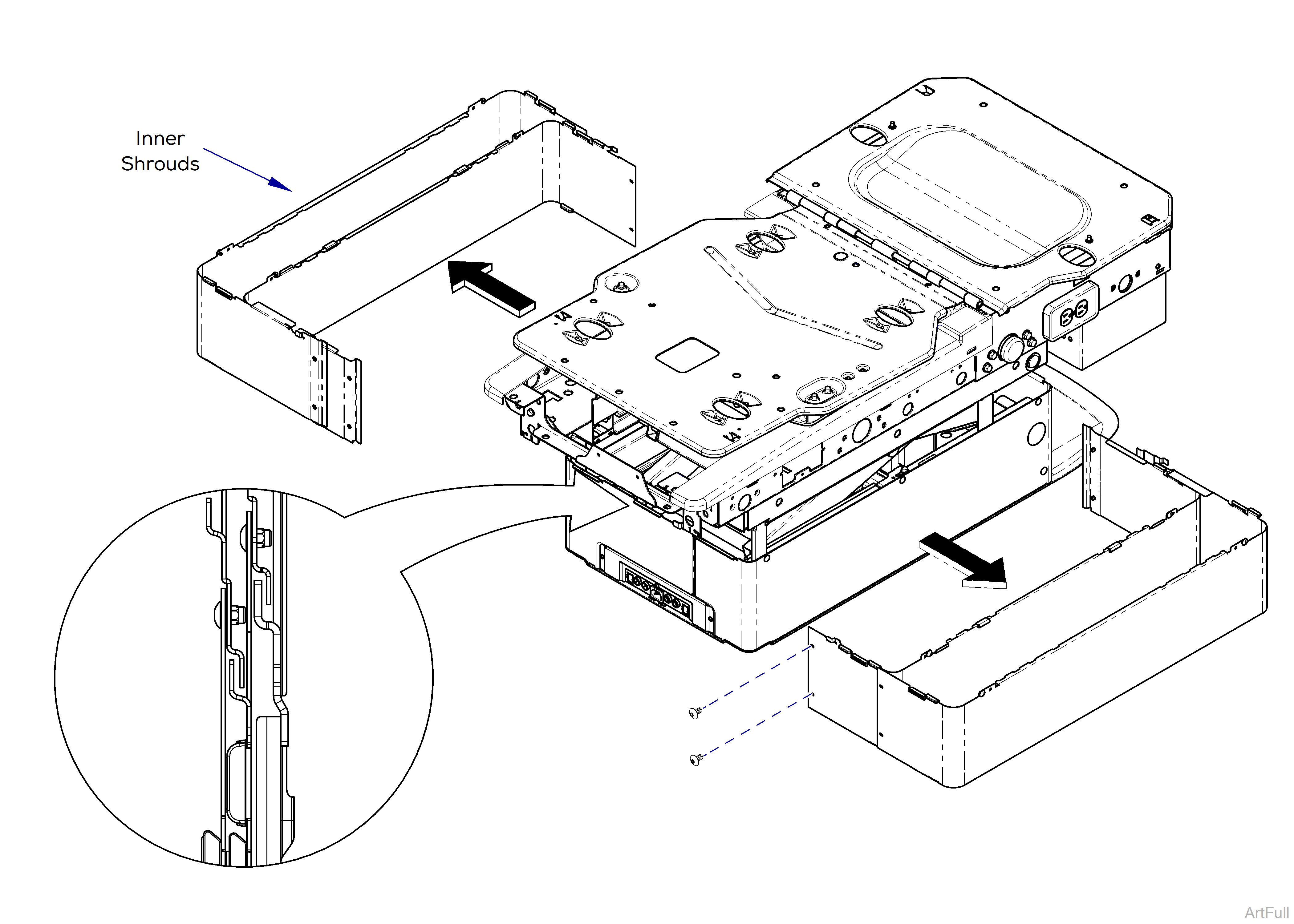
5.Remove screws from head-end and foot-end of Inner Shroud
6.Pull Inner Shroud away from chair to Remove. Repeat on remaining Shrouds.
Installation
1.Install Inner Shrouds by pairing them up and screwing ends together.
2.Install outer shroud by inserting Front and Back Tabs into chair frame. Install screws into sides of chair frame and ends of shrouds.
3.Install Front Drawer into slides and secure with retaining screw.
4.Position and secure Rear Cover with screws.
5.Install Side Cladding by hooking top edge onto chair, then pushing in at tab locations until they engage the chair frame.
6.Position top cover in place while engaging tabs into chair, secure with two screws.
If the chair is lowered and inoperable, the Motor Control PC Board can be accessed by separating and spreading the shrouds at the head end of chair.
Do not spread shrouds more than necessary to access PC Board or equipment could be damage.
To Separate Shrouds
1.Remove two screws from both sides of Outer Shrouds.
2.Remove screws from head-end of Outer Shrouds.
3.Pull Outer Shroud away from chair and lower the Tabs out of slots.
4.Remove screws from head-end Inner Shrouds.
5.Carefully spread Shrouds away from chair.
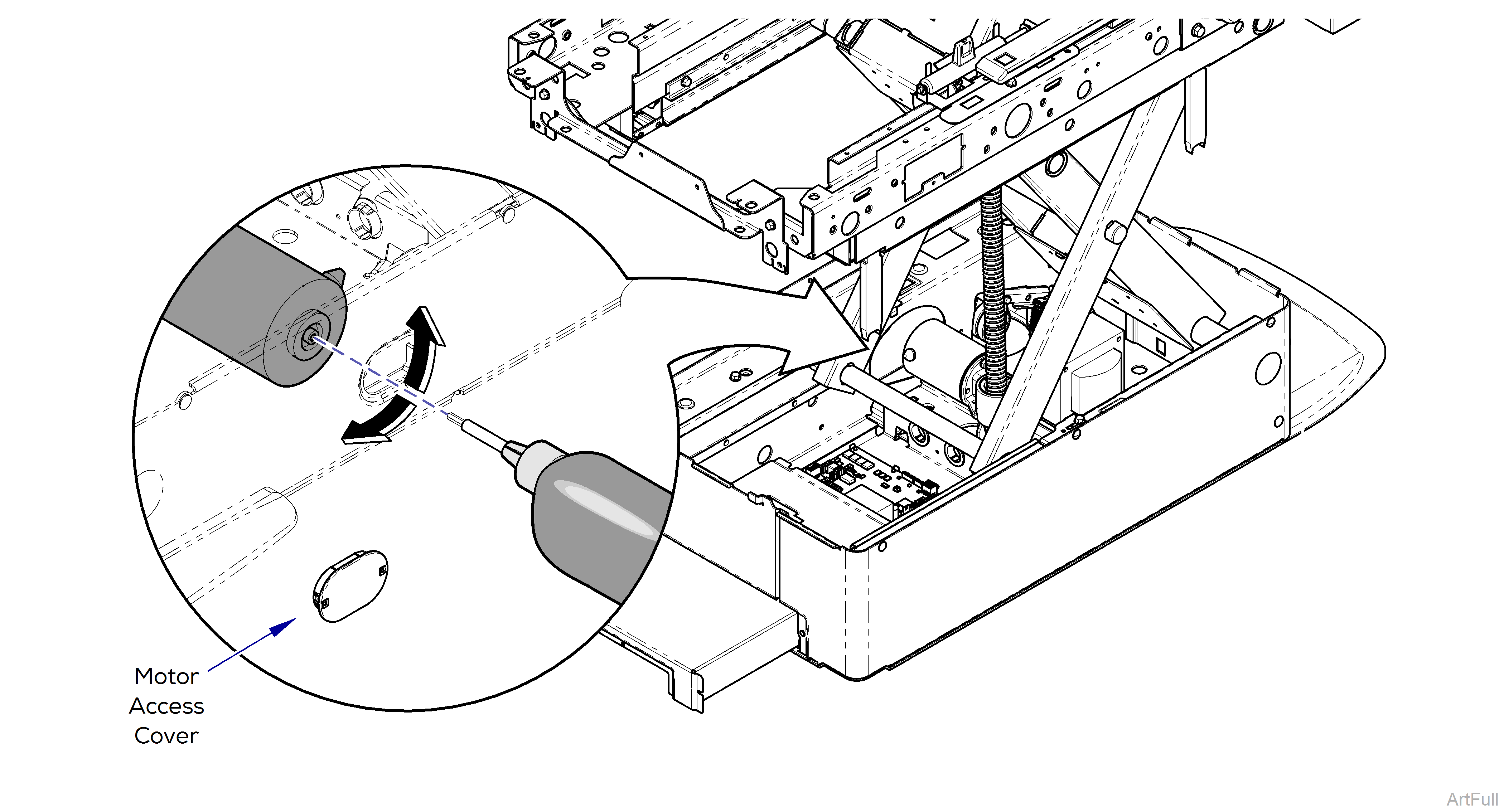
Do not move chair past limit switches or equipment could be damage.
The Base Actuator can be raised and lowered by removing the Motor Access Cover and using a drill, 3/16 allen bit and extension. Reverse (CCW) to raise actuator. Forward (CW) to lower actuator.