626 Chair Back Up / Down Function Theory of Operation
The illustrations show only the components that affect the Back Up / Down function. Refer to the dropdowns for a detailed description of the Back Up / Down operation.
|
Model |
626-001 and -002 |
| Serial Number | All |
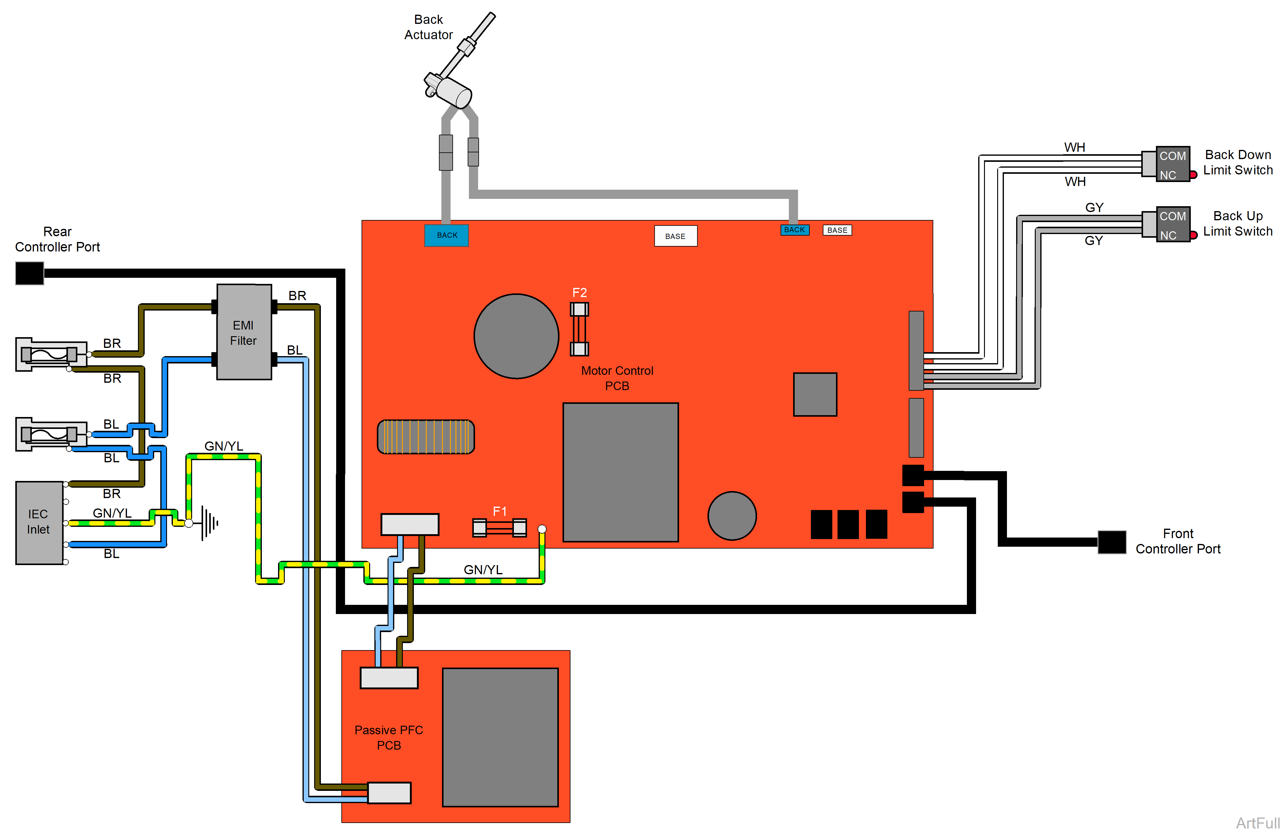
Line voltage (115 VAC) is supplied thru two primary fuses located at the table base.
The 115 VAC is sent thru the Passive PFC board to the Motor Control PC board. The Motor Control PC board reduces the voltage to 3.3 VDC which is supplied to the foot / hand control.
Fuse F1 on the Motor Control PC board protects the transformer on the board and the electronics supplied by the transformer.
When the Back Up function is activated, the foot / hand control sends a command to the Motor Control PC Board. The Motor Control PC board supplies the correct voltage to the Back actuator motor.
Fuse F2 on the Motor Control PC board protects the Back actuator motor.
The actuator motor runs and raises the Back section.
The actuator motor runs until:
•Foot / Hand control button is released.
•Stop button is pressed.
•Back Up limit switch is tripped.
•Overcurrent protection tripped.
When the Back Down function is activated, the foot / hand control sends a command to the Motor Control PC board. The Motor Control PC board supplies the correct voltage to the Back actuator motor.
Fuse F2 on the Motor Control PC board protects the Back actuator motor.
The actuator motor runs and lowers the Back section.
The actuator motor runs until:
•Foot / Hand control button is released.
•Stop button is pressed.
•Back Down limit switch is tripped.
•Overcurrent protection tripped.
|
Model |
626-003 and -004 |
| Serial Number | All |
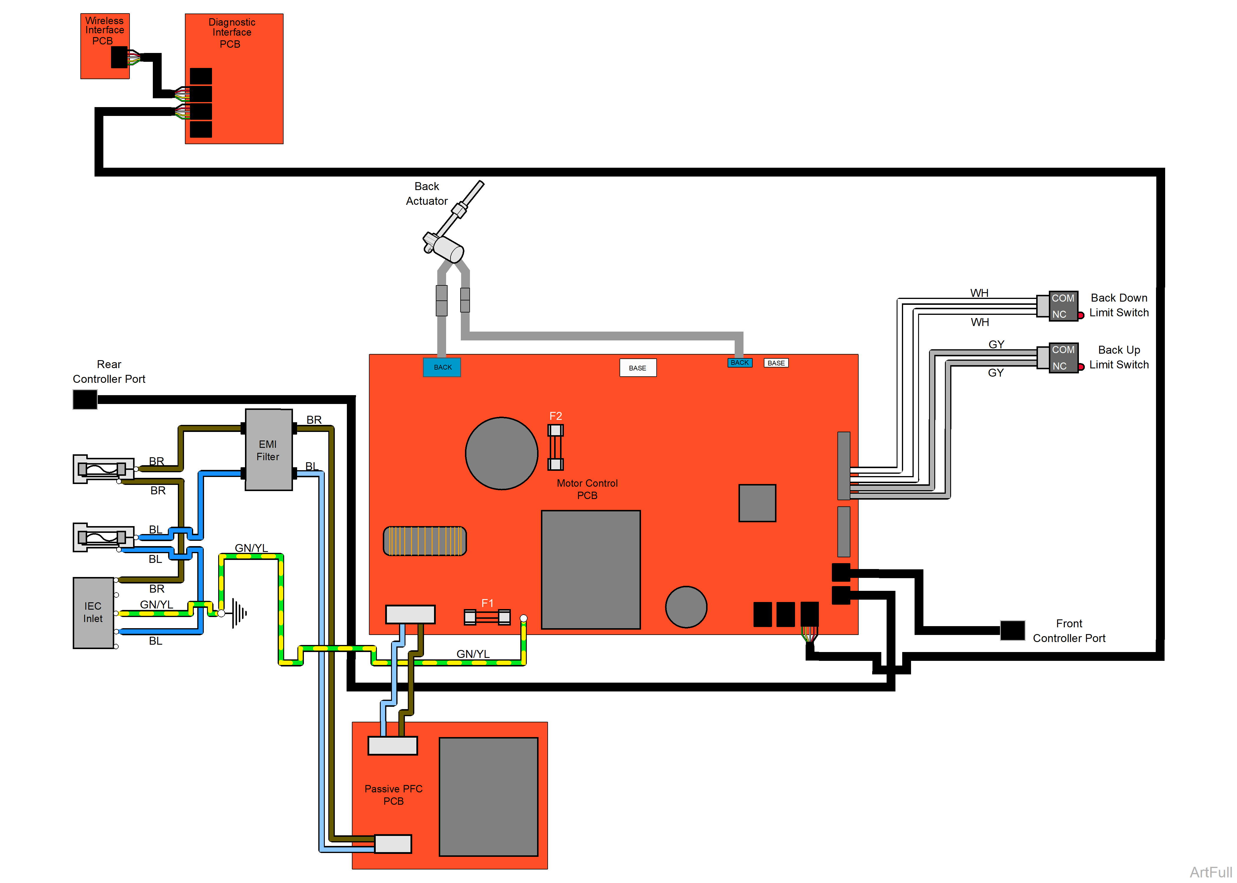
Line voltage (115 VAC) is supplied thru two primary fuses located at the table base.
The 115 VAC is sent thru the Passive PFC board to the Motor Control PC board. The Motor Control PC board reduces the voltage to 12 VDC which is supplied thru the Diagnostic Interface PC board to the Wireless Interface PC board. The Wireless Interface PC board transmits a signal to the foot / hand controls.
Fuse F1 on the Motor Control PC board protects the transformer on the board and the electronics supplied by the transformer.
When the Back Up function is activated, the foot / hand control transmits a signal to the Wireless Interface PC board. That command is sent thru the Diagnostic Interface PC board to the Motor Control PC Board. The Motor Control PC board supplies the correct voltage to the Back actuator motor.
Fuse F2 on the Motor Control PC board protects the Back actuator motor.
The actuator motor runs and raises the Back section.
The actuator motor runs until:
•Foot / Hand control button is released.
•Stop button is pressed.
•Back Up limit switch is tripped.
•Overcurrent protection tripped.
When the Back Down function is activated, the foot / hand control transmits a signal to the Wireless Interface PC board. That command is sent thru the Diagnostic Interface PC board to the Motor Control PC Board. The Motor Control PC board supplies the correct voltage to the Back actuator motor.
Fuse F2 on the Motor Control PC board protects the Back actuator motor.
The actuator motor runs and lowers the Back section.
The actuator motor runs until:
•Foot / Hand control button is released.
•Stop button is pressed.
•Back Down limit switch is tripped.
•Overcurrent protection tripped.
|
Model |
626-005 and -006 |
| Serial Number | All |
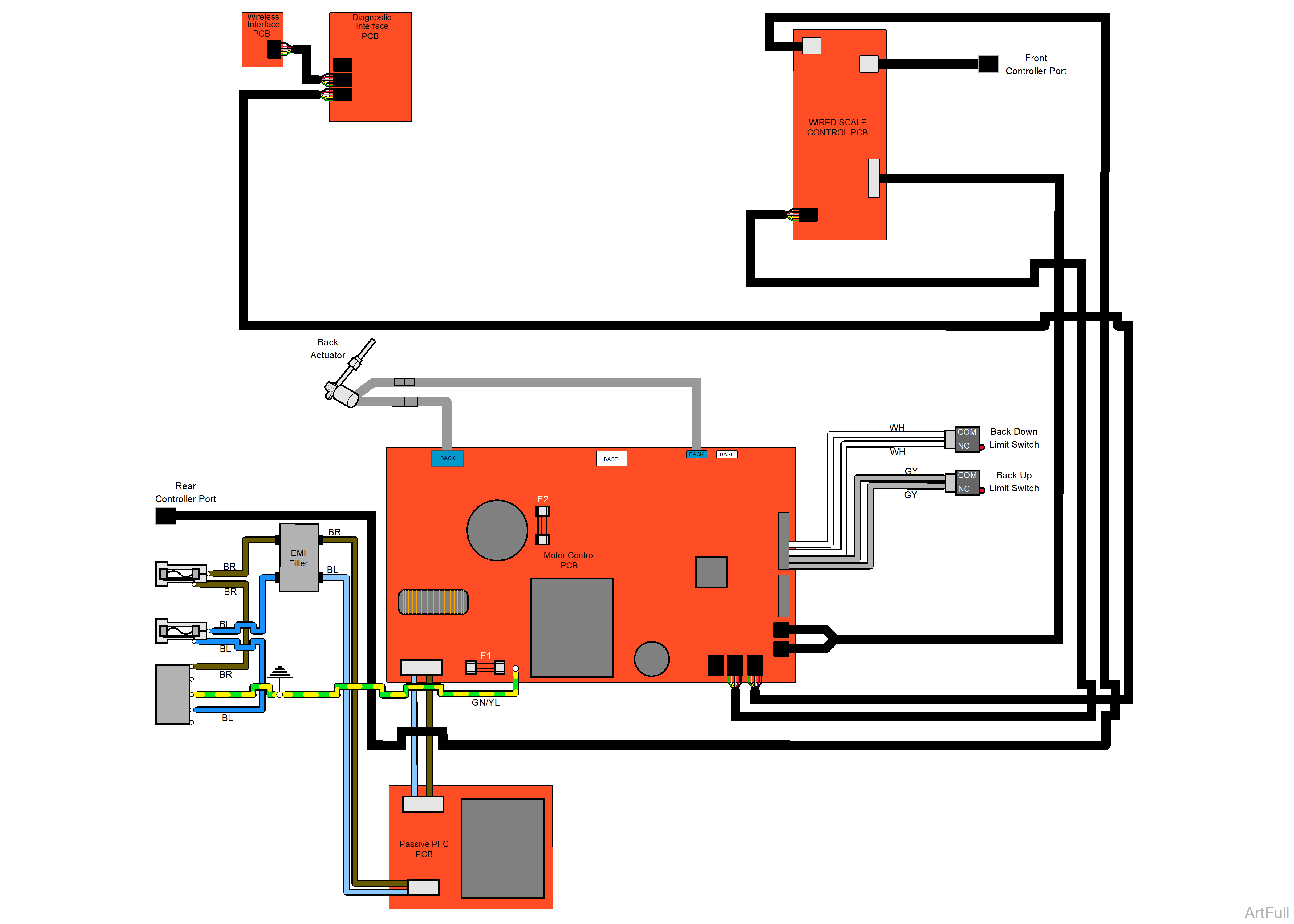
Line voltage (115 VAC) is supplied thru two primary fuses located at the table base.
The 115 VAC is sent thru the Passive PFC board to the Motor Control PC board. The Motor Control PC board reduces the voltage to 3.3 VDC which is supplied thru the Wired Scale Control PC board to the foot / hand control.
Fuse F1 on the Motor Control PC board protects the transformer on the board and the electronics supplied by the transformer.
When the Back Up function is activated, the foot / hand control sends a command thru the Wired Scale Control PC board to the Motor Control PC Board. The Motor Control PC board supplies the correct voltage to the Back actuator motor.
Fuse F2 on the Motor Control PC board protects the Back actuator motor.
The actuator motor runs and raises the Back section.
The actuator motor runs until:
•Foot / Hand control button is released.
•Stop button is pressed.
•Back Up limit switch is tripped.
•Overcurrent protection tripped.
When the Back Down function is activated, the foot / hand control sends a command thru the Wired Scale Control PC board to the Motor Control PC Board. The Motor Control PC board supplies the correct voltage to the Back actuator motor.
Fuse F2 on the Motor Control PC board protects the Back actuator motor.
The actuator motor runs and lowers the Back section.
The actuator motor runs until:
•Foot / Hand control button is released.
•Stop button is pressed.
•Back Down limit switch is tripped.
•Overcurrent protection tripped.
