626 Chair Load Cell Test - Diagnostic PCB Test and Repair
1.Power up chair.
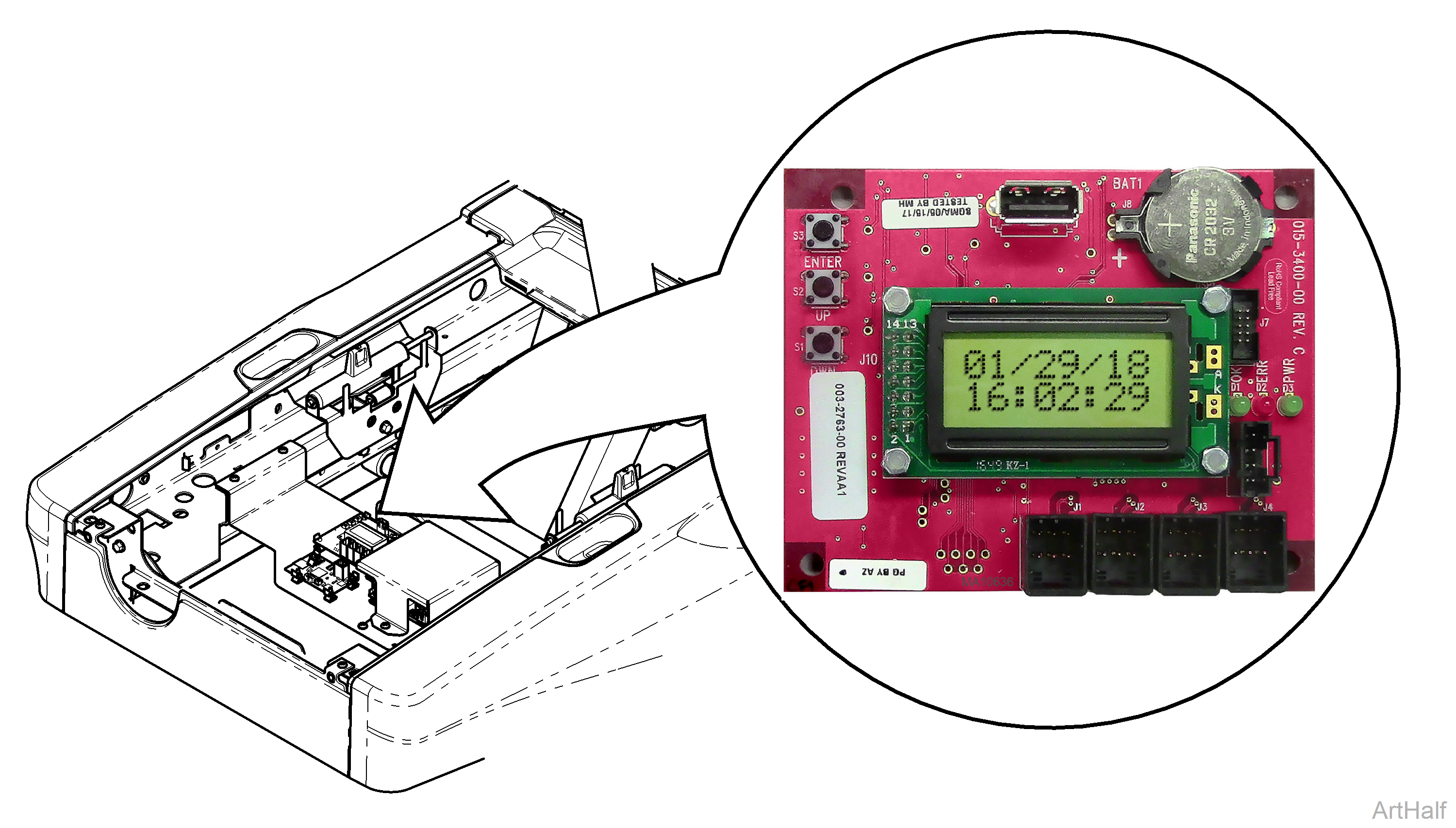
2.Locate the Diagnostic PC Board.
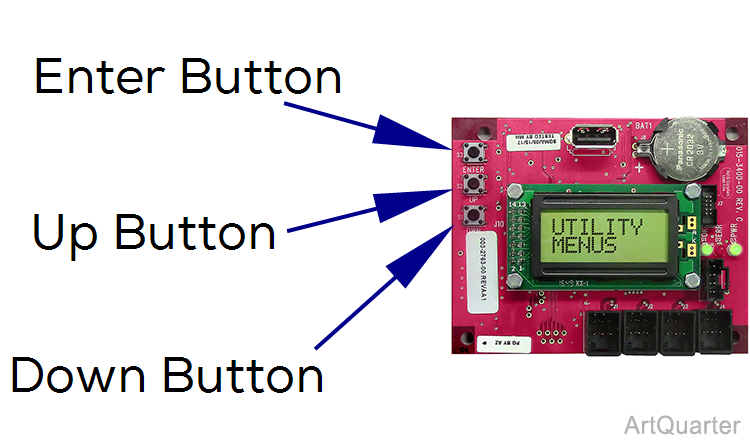
3.Press and release the Up or Down button until Utility Menus is displayed.
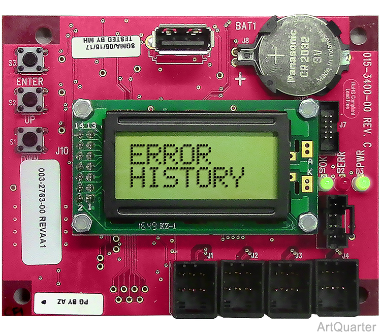
4.Press Enter button once and Error History is displayed.
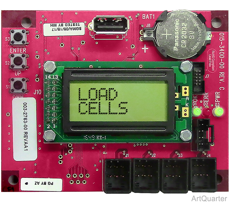

5.Press the Down until Load Cells is displayed. Then pres enter.
6.Press Enter button once and the Front and Back ADC count values are displayed.
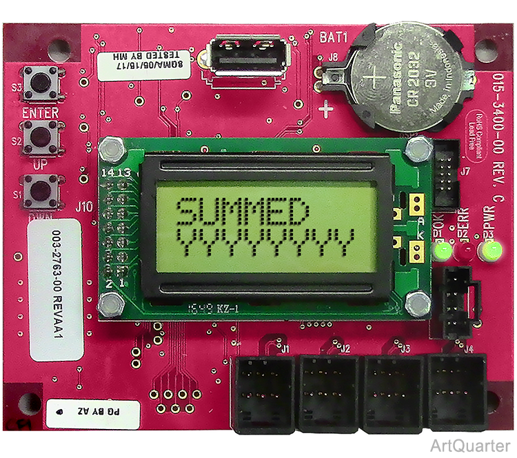
7.Press Down button once and the Summed ADC count value is displayed.
Where F and B represent front and back load cells respectively, XXXXXX is a 24-bit hexadecimal number. SUMMED represents both front and back, YYYYYYYY is a 32-bit hexadecimal number. Each hexadecimal number represents the load cell ADC count value. Basic sequence of numbers: 0,1,2,3,4,5,6,7,8,9,A,B,C,D,E,F. Once it reaches F, it goes to 10,11,12,13,14,15,16,17,18,19,1A,1B, 1C,1D,1E,1F. Once it reaches 1F, it goes to 20,21,22, and so on.
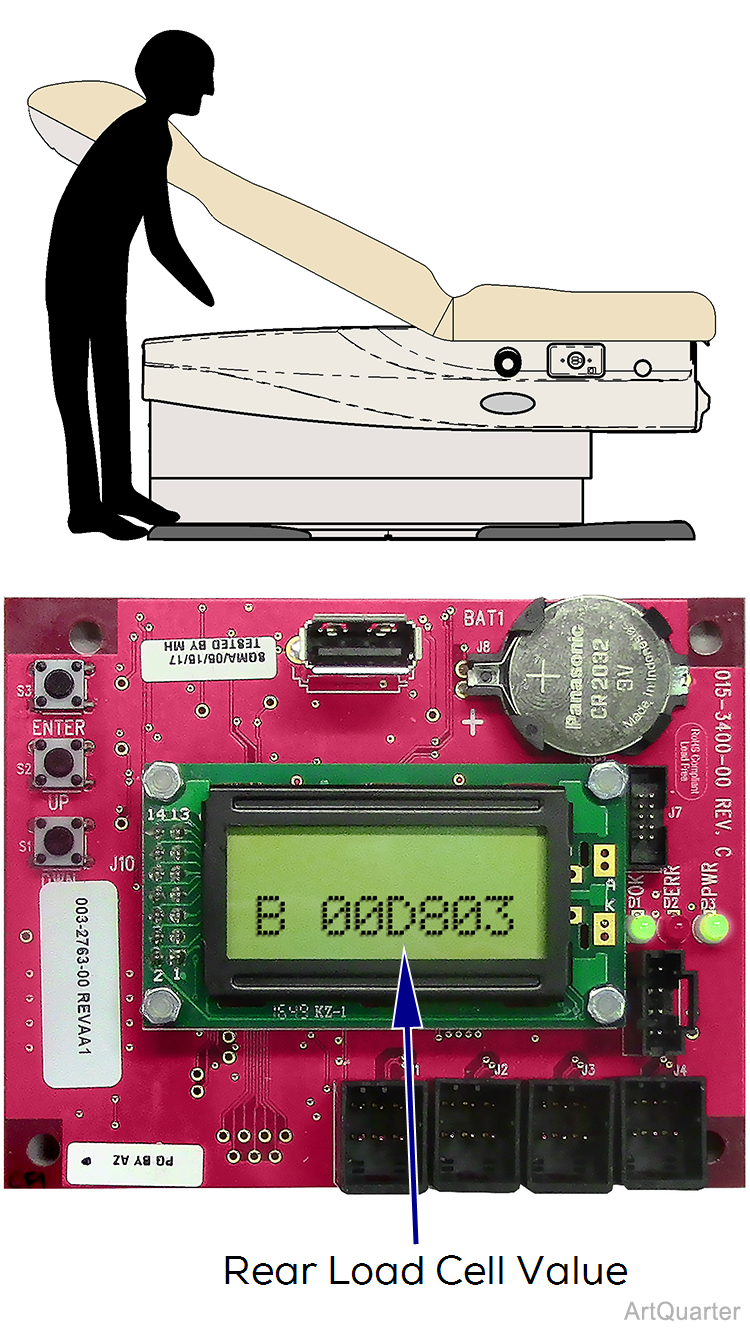
When applying weight to the Rear load cells an increase in the ADC count value out to the fourth digit should be seen.
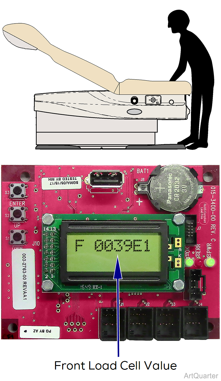
When applying weight to the Front load cells an increase in the ADC count value out to the fourth digit should be seen.
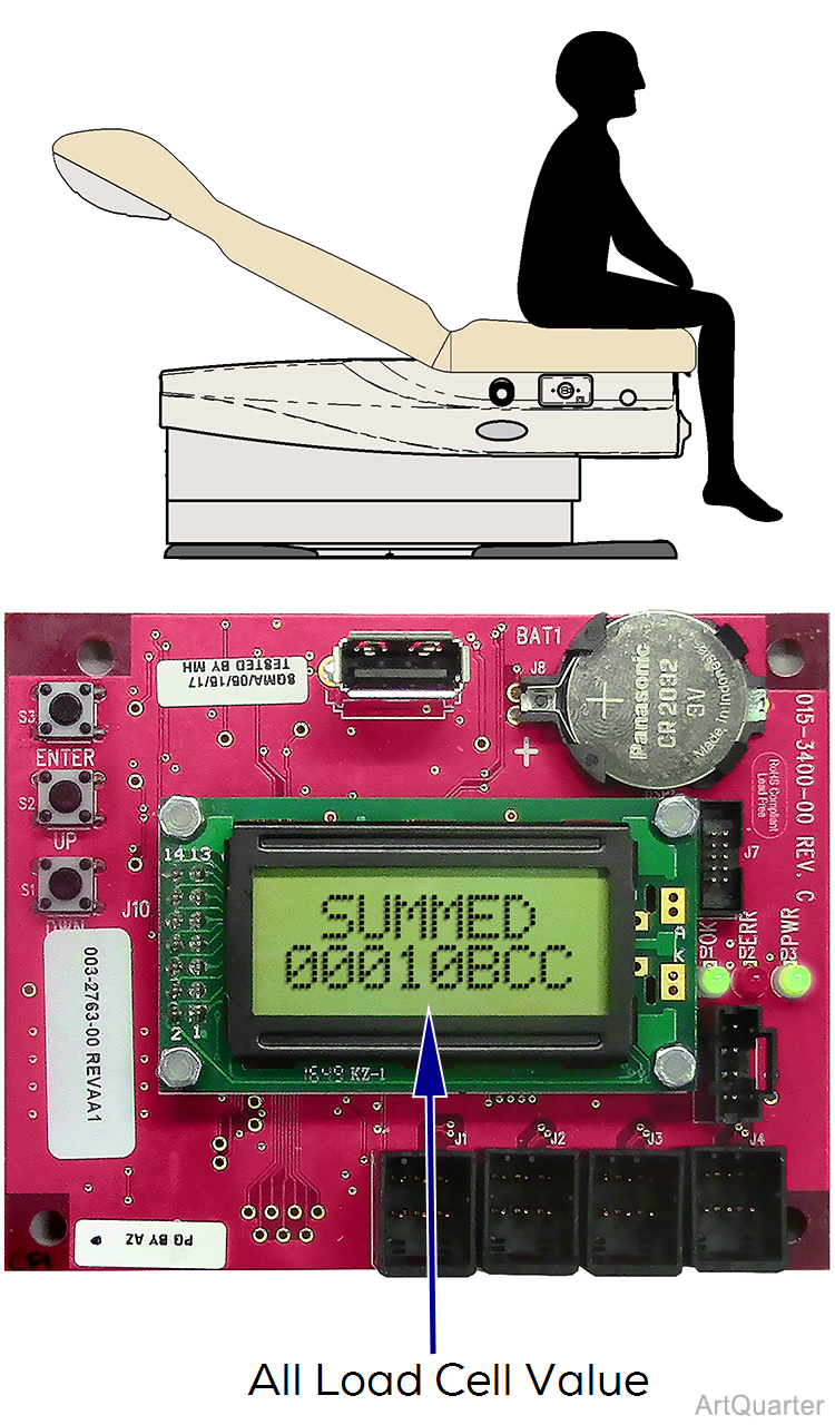
When applying weight to the ALL load cells an increase in the ADC count value out to the fourth or fifth digit should be seen.
