626 Chair Upholstery Heater / Fuses and Connections Test and Repair
|
Model |
626 -002 and 626-004 |
| Serial Number | V2200 thru V1998434 |
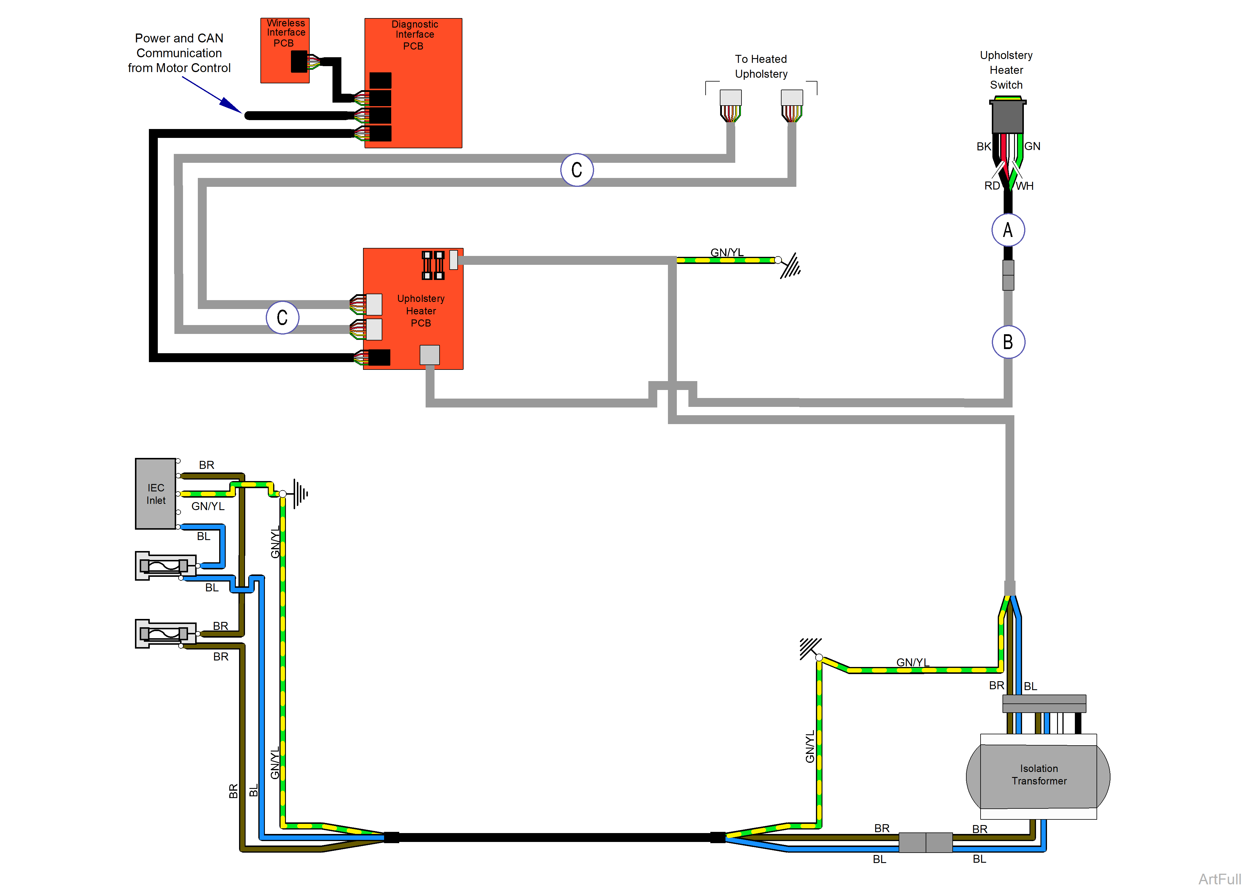
There is one heater for the back and one heater for the seat. Each heater is independently controlled by the upholstery heater board. Each heater has an independent thermistor (temperature sensor) that feeds back into the control. The thermistor should read about 10k ohms when measured with a multimeter. This resistance changes if the heater is warm. The upholstery heater outputs are approximately 14VAC to each heater when starting from cold temperature.
1) No light on upholstery switch.
When the Heated Upholstery button is pressed, switch does not illuminate.
Check connections...
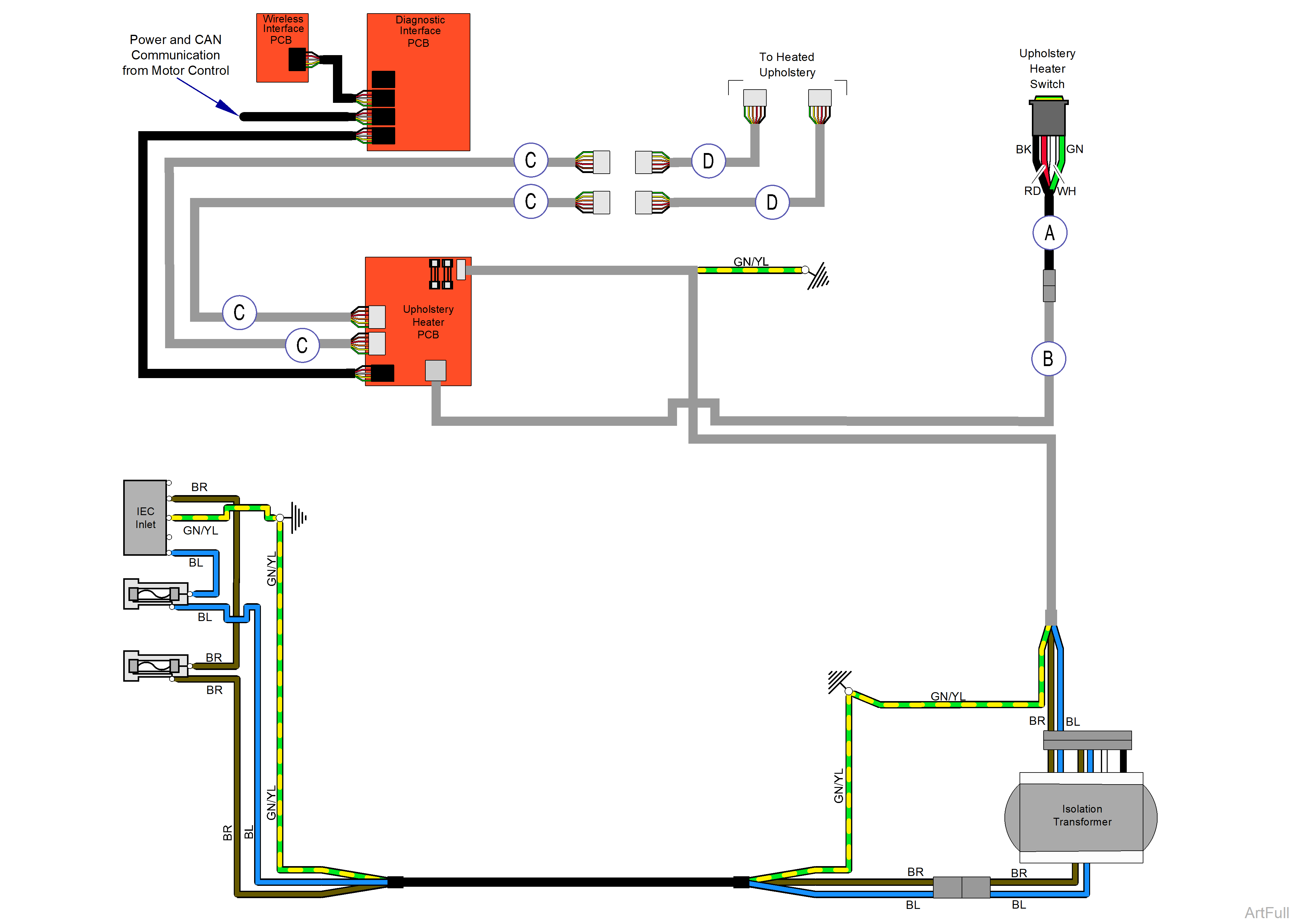
Check that the connection from the switch to harness A is correct.
Check that connection on harness B is correct at the junction to harness A and the upholstery PC board. Then cycle power.
Check switch function...
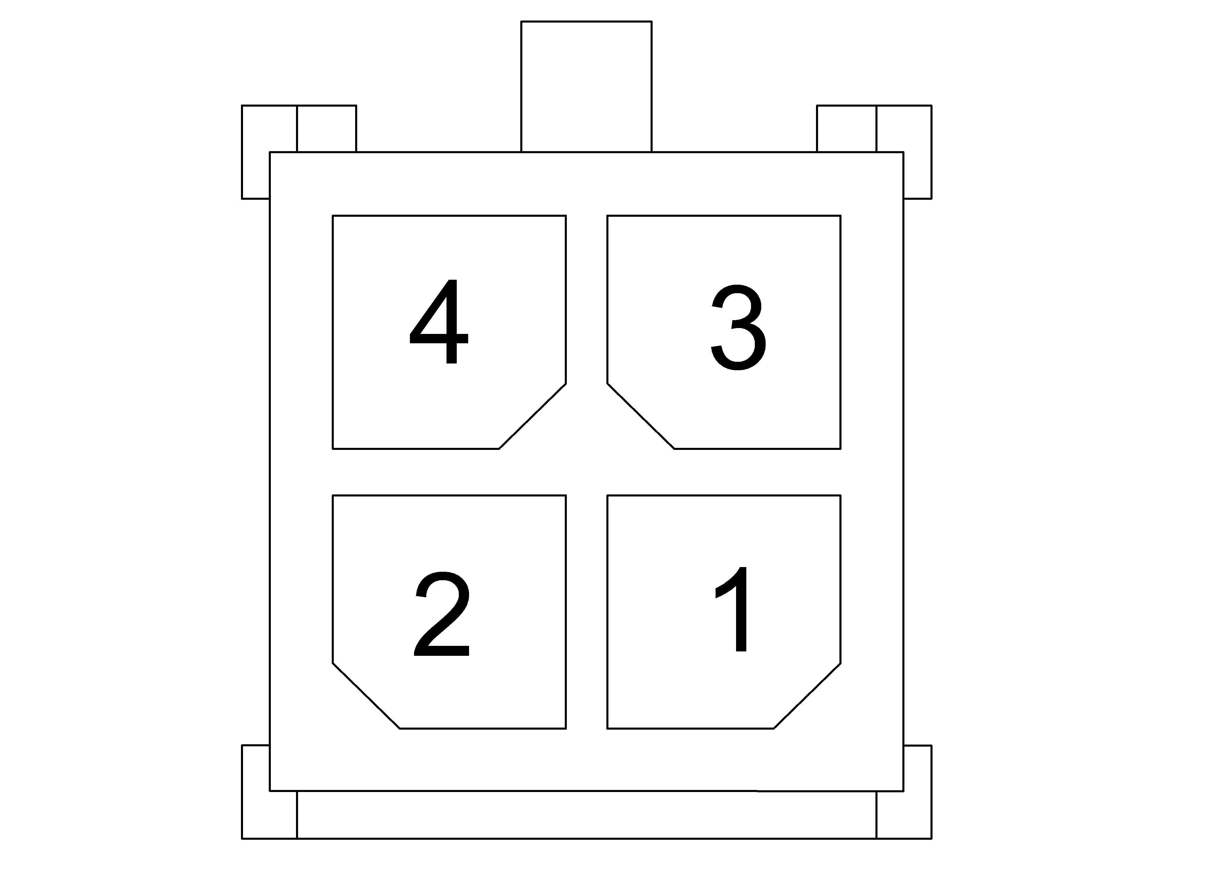
Disconnect the switch. Check pins 1 and 2 with a multimeter, the reading should be OL when the switch is not being pressed. When pressing the switch, the reading should be 5 Ohms or less.
If readings are different replace the switch. (reference below image)
2) Flickering Upholstery light
When activating the heated upholstery the light flickers.
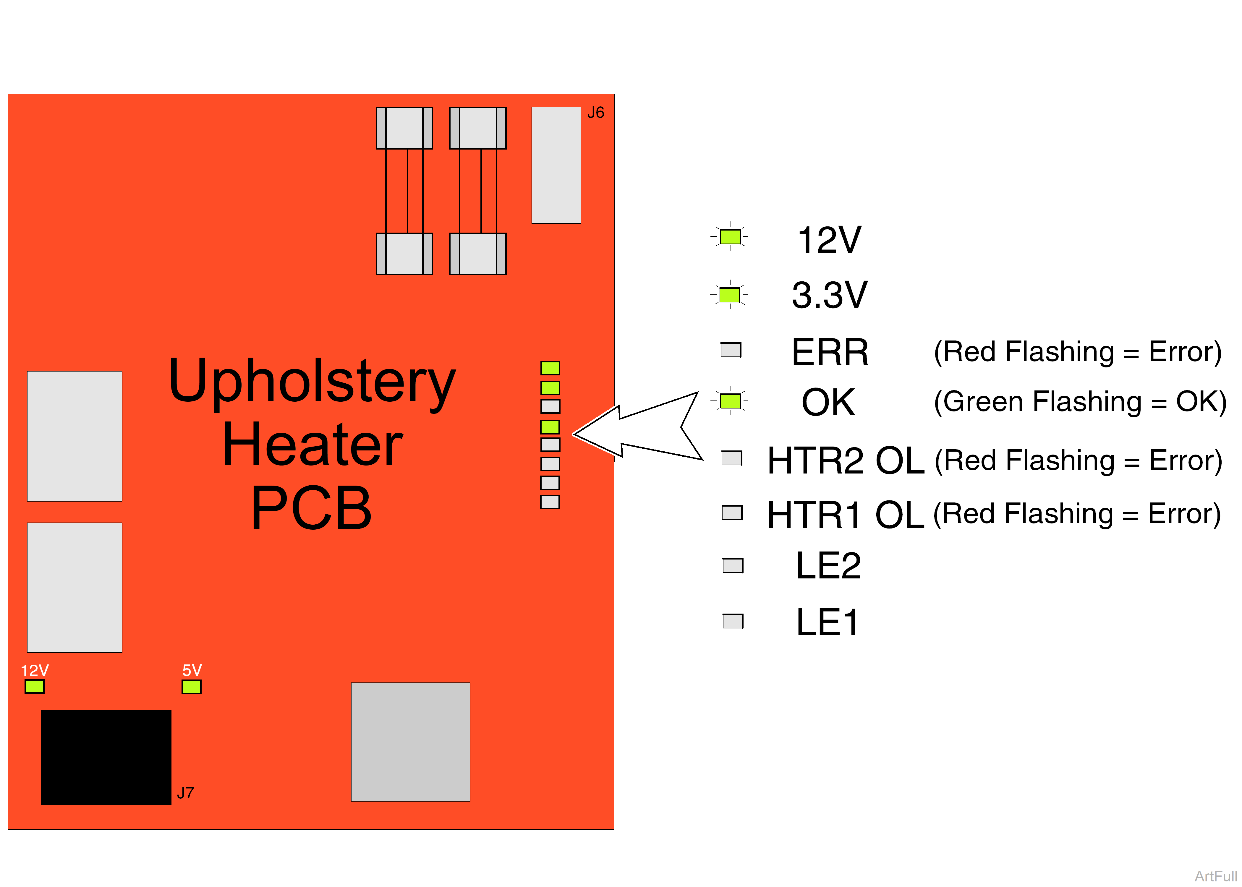
Check the upholstery PC board. There are two heater error lights. If either or both are on, the PC board does not detect the temperature sensors in the heated upholstery. Disconnect the heated upholstery, check each 6-pin connection individually with a multimeter for resistance.
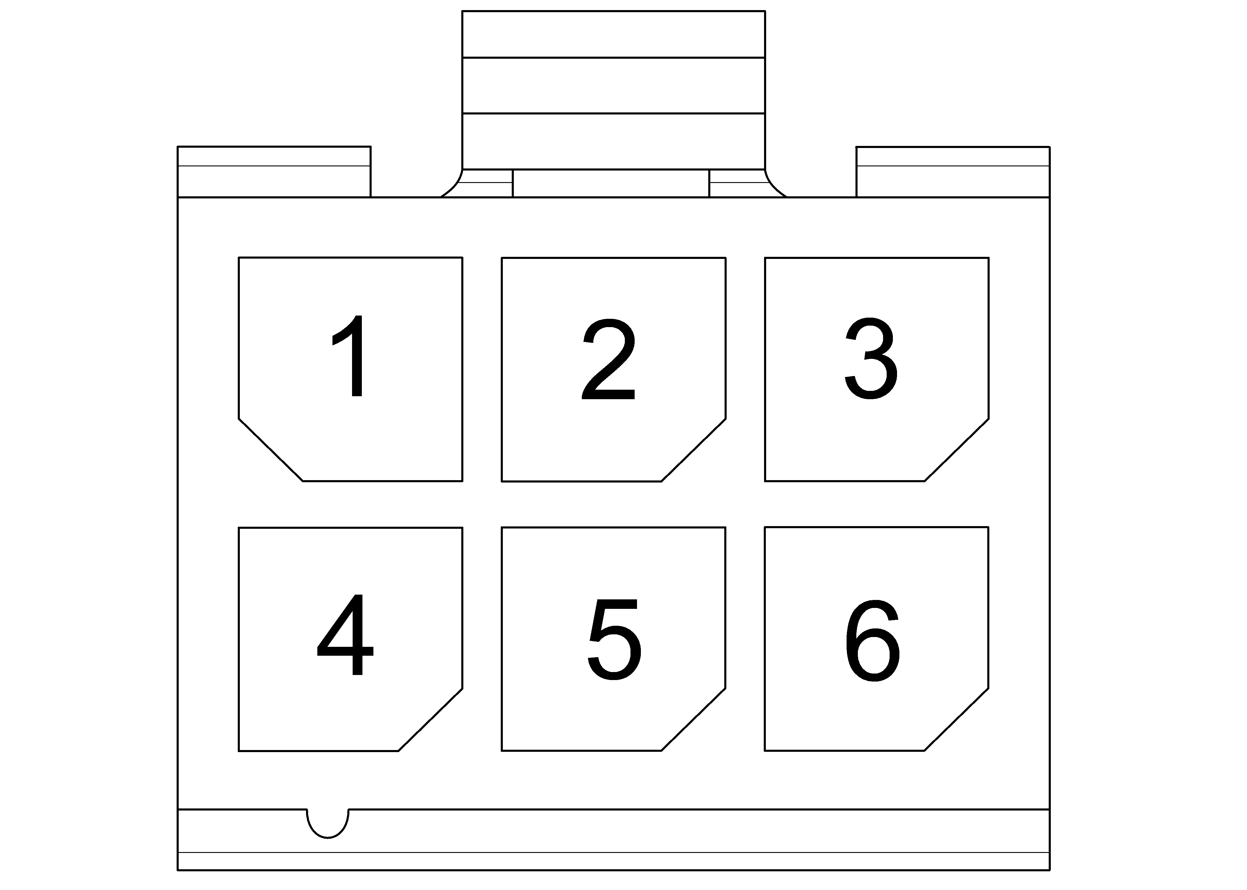
Using the image below, check each set of connections on both the back and seat heater connectors. Pins 1 and 4 are the heater. This should be approximately 11.5 Ohms. This is not the cause of the light flickering. Pins 2 and 5, and pins 3 and 6 are both temperature sensors. Pins 2 to 5 should measure close to 10K Ohms when at room temp. Pins 3 to 6 should measure the same. If reading is less than 9.5K Ohms or higher than 10.5K Ohms, the temp sensors are most likely faulty and the upholstery needs replaced. If the readings are correct, check continuity through harnesses C from where they connect to the upholstery to where they connect to the PC board. If continuity is present, it’s most likely the PC board that has the issue. You can also have an error with the heaters if you have disconnected the heaters while the chair is on. There is a timed reset after you reconnect the heaters before the errors clear. Cycle power to the chair and check that the errors have cleared
| Pin Assignment | ||
|
Pins 1 and 4 |
Heater | 11.5 Ohms |
| Pins 2 and 5 | Thermistor 1 | 10K Ohms |
| Pins 3 and 6 | Thermistor 2 | 10K Ohms |
Looking at the front of the connection coming from the Upholstery
3) PCB Diagnostics
When ever you have any error light on the upholstery PC board, check the active errors on the diagnostic PC board to determine what the exact issue is with the board. The J7 connection, if connected correctly will allow a 12V and 5V light to be lit near J7. As well as a flashing OK light. This is the connection to the rest of the chairs PCB system. The J6 connection is powered by the large transformer in the bottom of the chair. This supplies the voltage that powers the upholstery heaters. If you probe though the back of the connector while connected or disconnect, you should read 14VDC. An appropriate range would be 12VDC to 15VDC. If not, then check the connections at the transformer and the patient right hand two fuses near the power inlet.
|
Model |
626 -002, 626-004 and 626-006 |
| Serial Number | V1998435 thru Present |
There is one heater for the back and one heater for the seat. Each heater is independently controlled by the upholstery heater board. Each heater has an independent thermistor (temperature sensor) that feeds back into the control. The thermistor should read about 10k ohms when measured with a multimeter. This resistance changes if the heater is warm. The upholstery heater outputs are approximately 14VAC to each heater when starting from cold temperature.
1) No light on upholstery switch.
When the Heated Upholstery button is pressed, switch does not illuminate.
Check connections...
Check that the connection from the switch to harness A is correct.
Check that connection on harness B is correct at the junction to harness A and the upholstery PC board. Then cycle power.
Check switch function...
Disconnect the switch. Check pins 1 and 2 with a multimeter, the reading should be OL when the switch is not being pressed. When pressing the switch, the reading should be 5 Ohms or less.
If readings are different replace the switch. (reference below image)
2) Flickering Upholstery light
When activating the heated upholstery the light flickers.
Check the upholstery PC board. There are two heater error lights. If either or both are on, the PC board does not detect the temperature sensors in the heated upholstery. Disconnect the heated upholstery, check each 6-pin connection individually with a multimeter for resistance.
Using the image below, check each set of connections on both the back and seat heater connectors. Pins 1 and 4 are the heater. This should be approximately 11.5 Ohms. This is not the cause of the light flickering. Pins 2 and 5, and pins 3 and 6 are both temperature sensors. Pins 2 to 5 should measure close to 10K Ohms when at room temp. Pins 3 to 6 should measure the same. If reading is less than 9.5K Ohms or higher than 10.5K Ohms, the temp sensors are most likely faulty and the upholstery needs replaced. If the readings are correct, check continuity through the C and D harnesses from where they connect to the upholstery to where they connect to the PC board. If continuity is present, it’s most likely the PC board that has the issue. You can also have an error with the heaters if you have disconnected the heaters while the chair is on. There is a timed reset after you reconnect the heaters before the errors clear. Cycle power to the chair and check that the errors have cleared
| Pin Assignment | ||
|
Pins 1 and 4 |
Heater | 11.5 Ohms |
| Pins 2 and 5 | Thermistor 1 | 10K Ohms |
| Pins 3 and 6 | Thermistor 2 | 10K Ohms |
Looking at the front of the connection coming from the Upholstery
3) PCB Diagnostics
When ever you have any error light on the upholstery PC board, check the active errors on the diagnostic
PC board to determine what the exact issue is with the board. The J7 connection, if connected correctly will
allow a 12V and 5V light to be lit near J7. As well as a flashing OK light. This is the connection to the rest of
the chairs PCB system. The J6 connection is powered by the large transformer in the bottom of the chair.
This supplies the voltage that powers the upholstery heaters. If you probe though the back of the connector
while connected or disconnect, you should read 14VDC. An appropriate range would be 12VDC to 15VDC.
If not, then check the connections at the transformer and the patient right hand two fuses near the power
inlet.
