630 Chair Foot up / down Function Troubleshooting
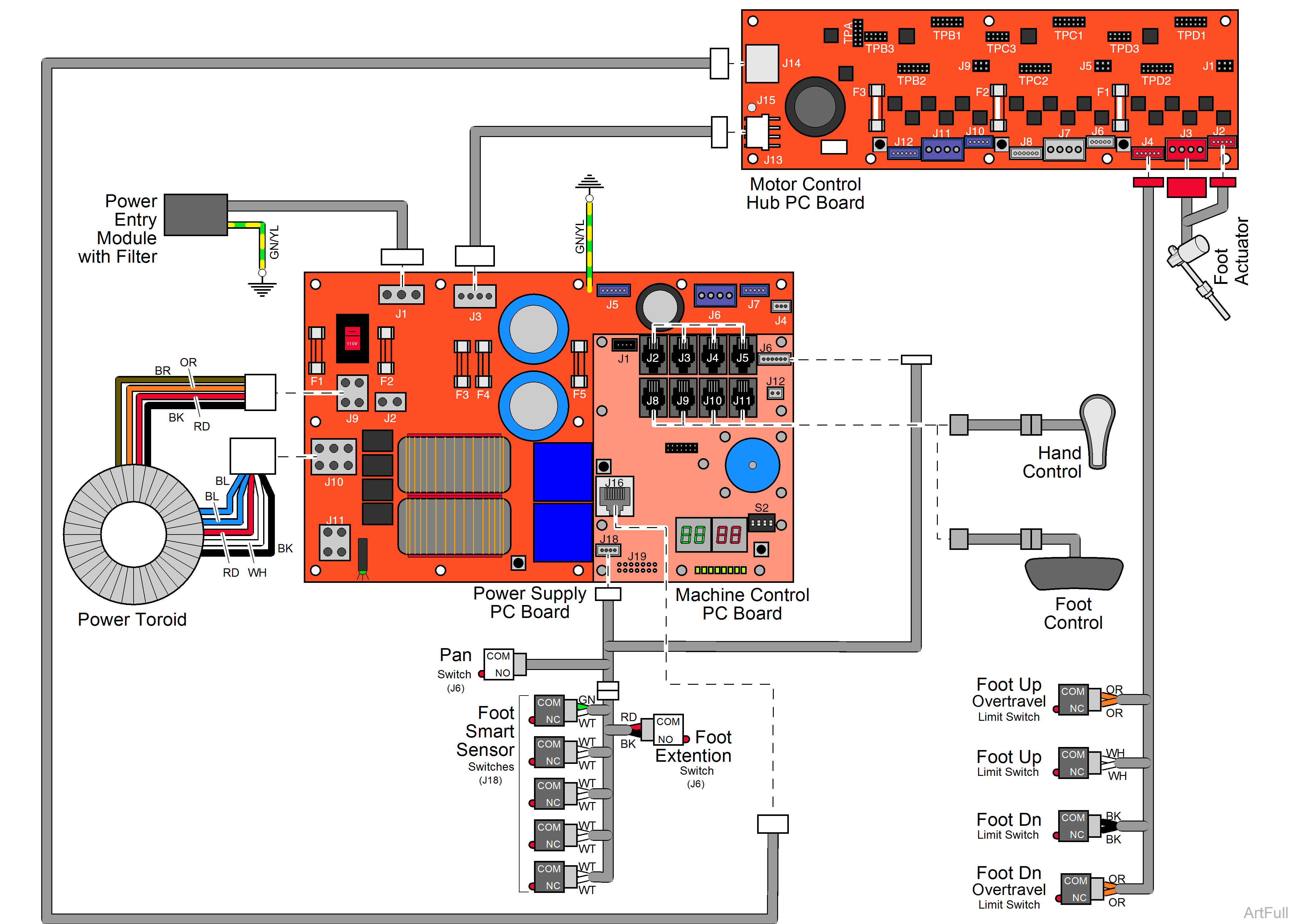
This illustration shows only the components that affect the Foot up / down function.
115 VAC is supplied thru the two primary fuses F1 and F2 on the Power Supply PC Board.
The Power Toroid reduces the line voltage to 25 VAC.
The Power Supply PC Board reduces the 25 VAC and supplies 12 VDC to the foot / hand control.
None of the actuator motors will run if the optional Rotation Base is unlocked.
When the Foot Up function is activated, the foot / hand control sends a command to the Machine Control PC Board. The Machine Control PC Board relays the command to the Power Supply PC Board.
+ 24 VDC is supplied thru fuse F3 and - 24 VDC is supplied thru fuse F4 on the Power Supply PC Board to the Motor Control Hub PC Board.
The Motor Control Hub PC Board supplies a commutation sequence to the foot actuator DC motor. F1 fuse on the Motor Control Hub PC Board protects the foot actuator motor.
The actuator motor runs and raises the foot section.
Actuator motor runs until:
1.Foot / Hand control button is released.
2.Foot Up limit switch is tripped.
3.Active Sensing Technology™ activated.
4.Foot Smart Sensor switch(es) activated.
5.Pan switch opens. Treatment pan is pulled out.
6.Stop button is pressed.
7.Overcurrent protection tripped.
8.Overtravel limit switch is tripped.
When the Foot Down function is activated, the foot / hand control sends a command to the Machine Control PC Board. The Machine Control PC Board relays the command to the Power Supply PC Board.
+ 24 VDC is supplied thru fuse F3 and - 24 VDC is supplied thru fuse F4 on the Power Supply PC Board to the Motor Control Hub PC Board.
The Motor Control Hub PC Board supplies a commutation sequence to the foot actuator DC motor. F1 fuse on the Motor Control Hub PC Board protects the foot actuator motor.
The actuator motor runs and lowers the foot section.
Actuator motor runs until:
1.Foot / Hand control button is released.
2.Foot Down limit switch is tripped.
3.Active Sensing Technology™ activated.
4.Foot Smart Sensor switch(es) activated.
5.Pan switch opens. Treatment pan is pulled out.
6.Stop button is pressed.
7.Overcurrent protection tripped.
8.Overtravel limit switch is tripped.
