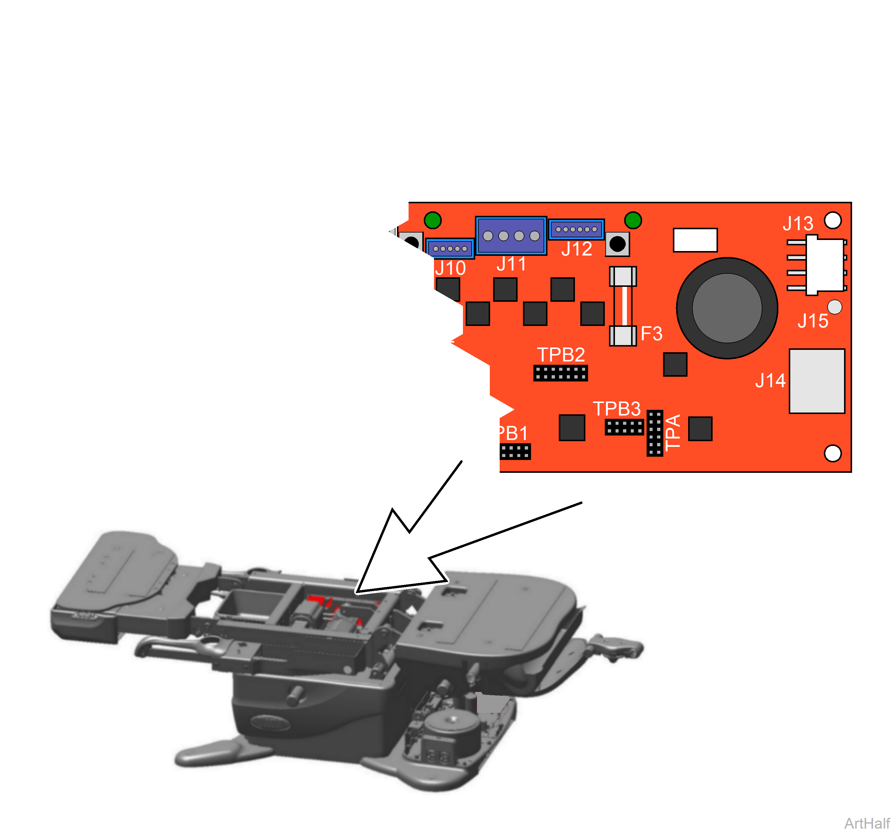
630 Chair Motor Control Hub PC Board Supply Power Test and Repair
The Power Supply PC Board supplies approximately + 36 VDC thru the Red wire, and - 36 VDC thru the White wire to the Motor Control Hub PC Board using the Black wire as the common.
Always remove power from chair before disconnecting or connecting J13 on Motor Control Hub PC Board or damage to PC Board may occur.
1.Disconnect power to the chair.
2.Disconnect J-13 harness from Motor Contol PC Board.
3.Connect power to chair.
4.Set meter to VDC.
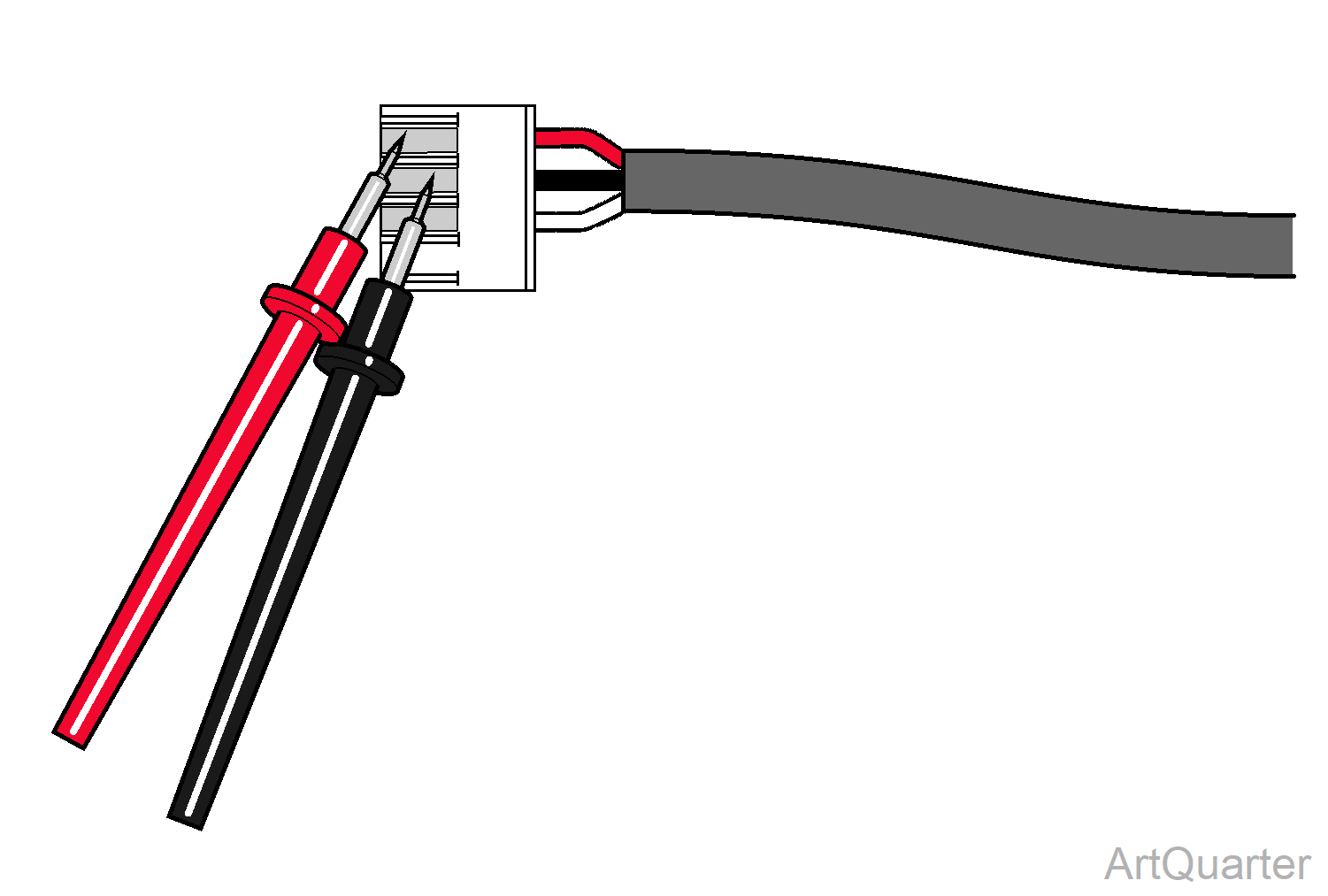
5.Place the Black meter probe on the Black wire (common) of J-13 harness. Place the Red meter probe on the Red wire of J-13 harness.
| Meter Reading | Required Action |
|---|---|
| + 36 VDC | Replace Motor Control Hub PC Board. |
| 0 VDC | Replace Power Supply PC Board. |
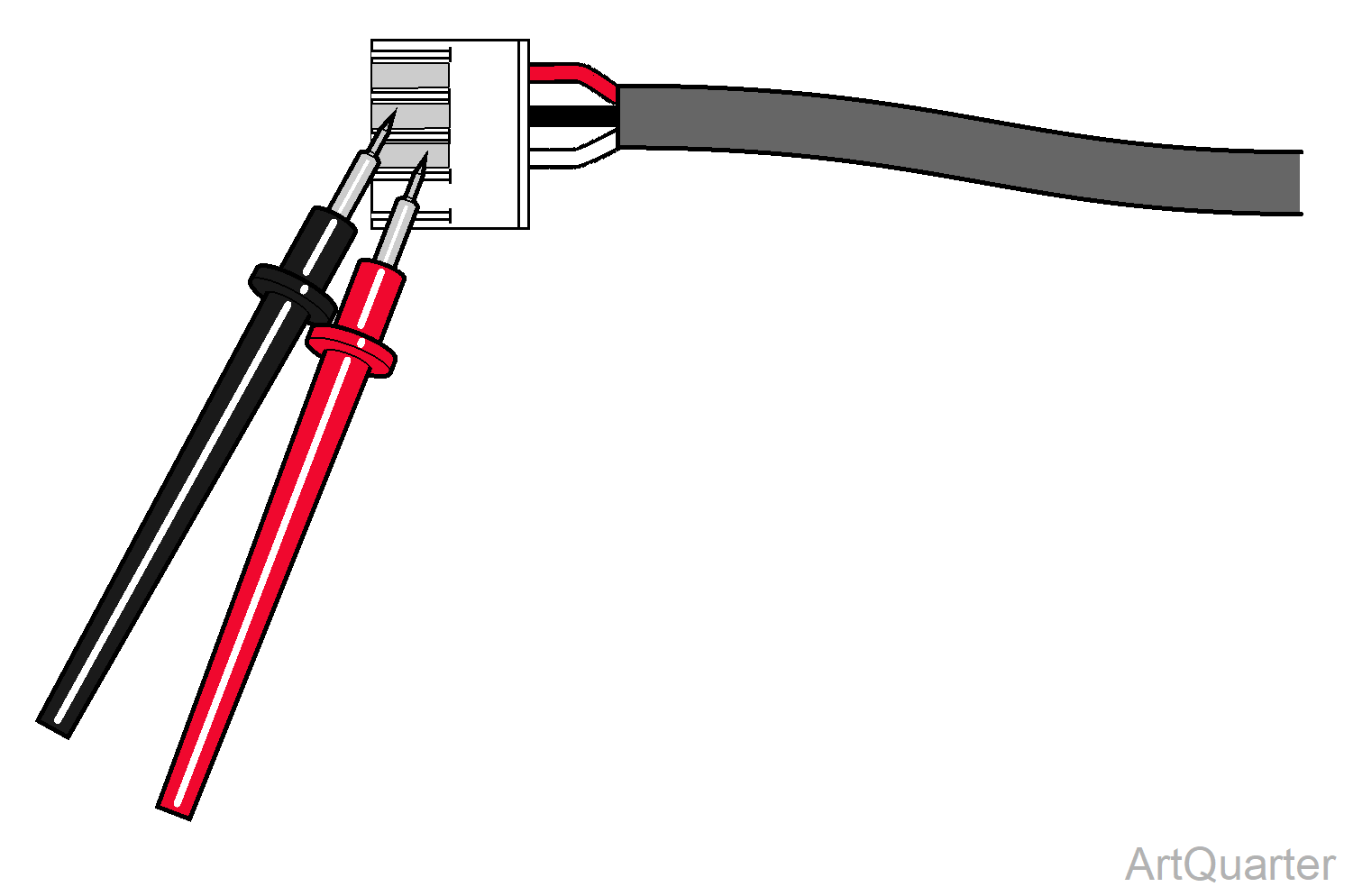
6.Place Black meter probe on the Black wire (common) of J-13 harness. Place the Red meter probe on the White wire of J-13 harness.
| Meter Reading | Required Action |
|---|---|
| - 36 VDC | Replace Motor Control Hub PC Board. |
| 0 VDC | Replace Power Supply PC Board. |
