630 Chair Separating Upper and Lower Base Castings Test and Repair
Ensure support does not make contact with foot sensor cover.
The chair weighs approximately 550 lbs (249 kg). Use supports designed for this amount of weight.
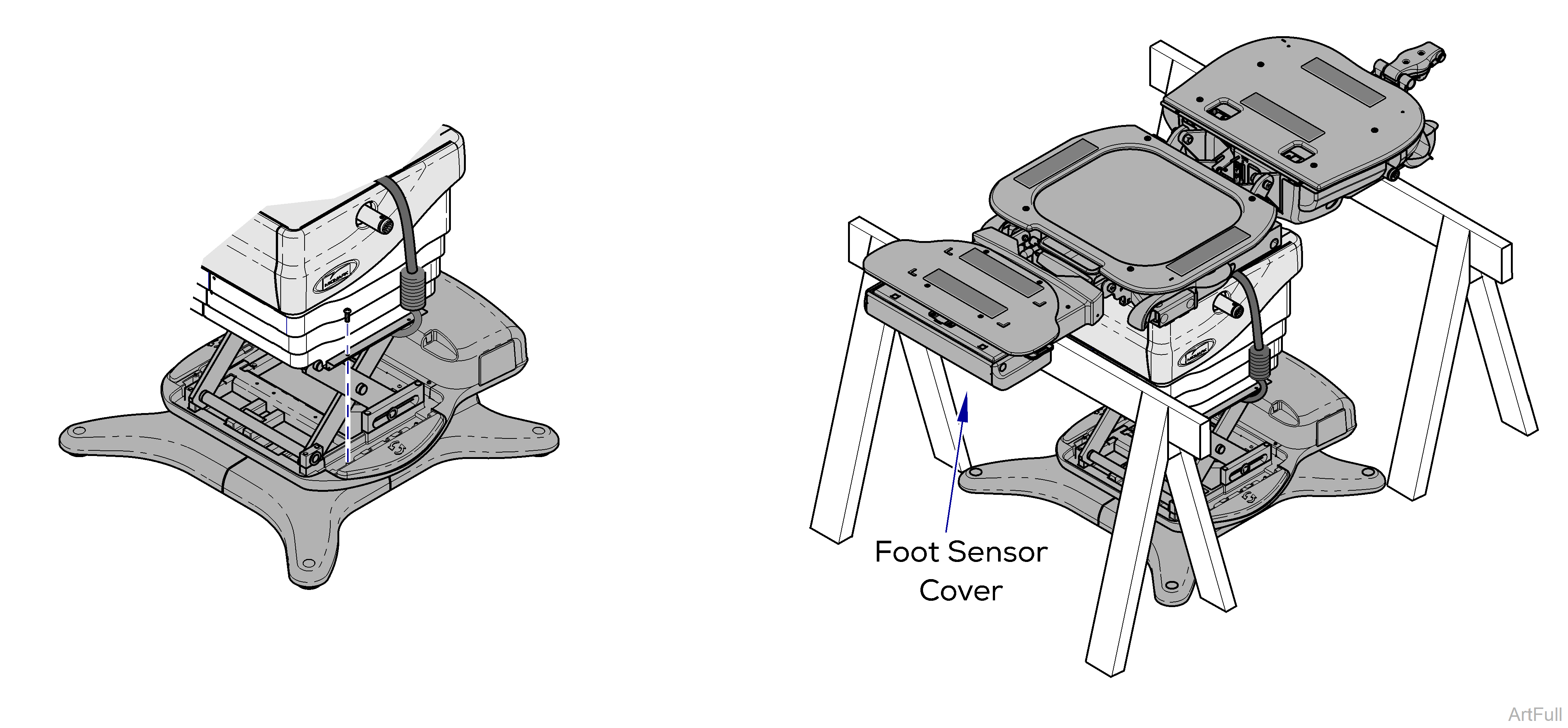
Steps 1 thru 8 require power to be connected to the chair. Avoid all contact with wiring and electrical components.
1.Remove four screws from inner shrouds.
2.Raise base shrouds. Refer to: Raising Base Shrouds / Cladding w/ bungee cord.
3.Press Base Up on hand / foot control to raise chair height.
4.Position sawhorses or other suitable supports, under back section and foot section.
The chair top / upper base is not secured once the hub screws are removed. Hold onto the chair when performing the following steps.
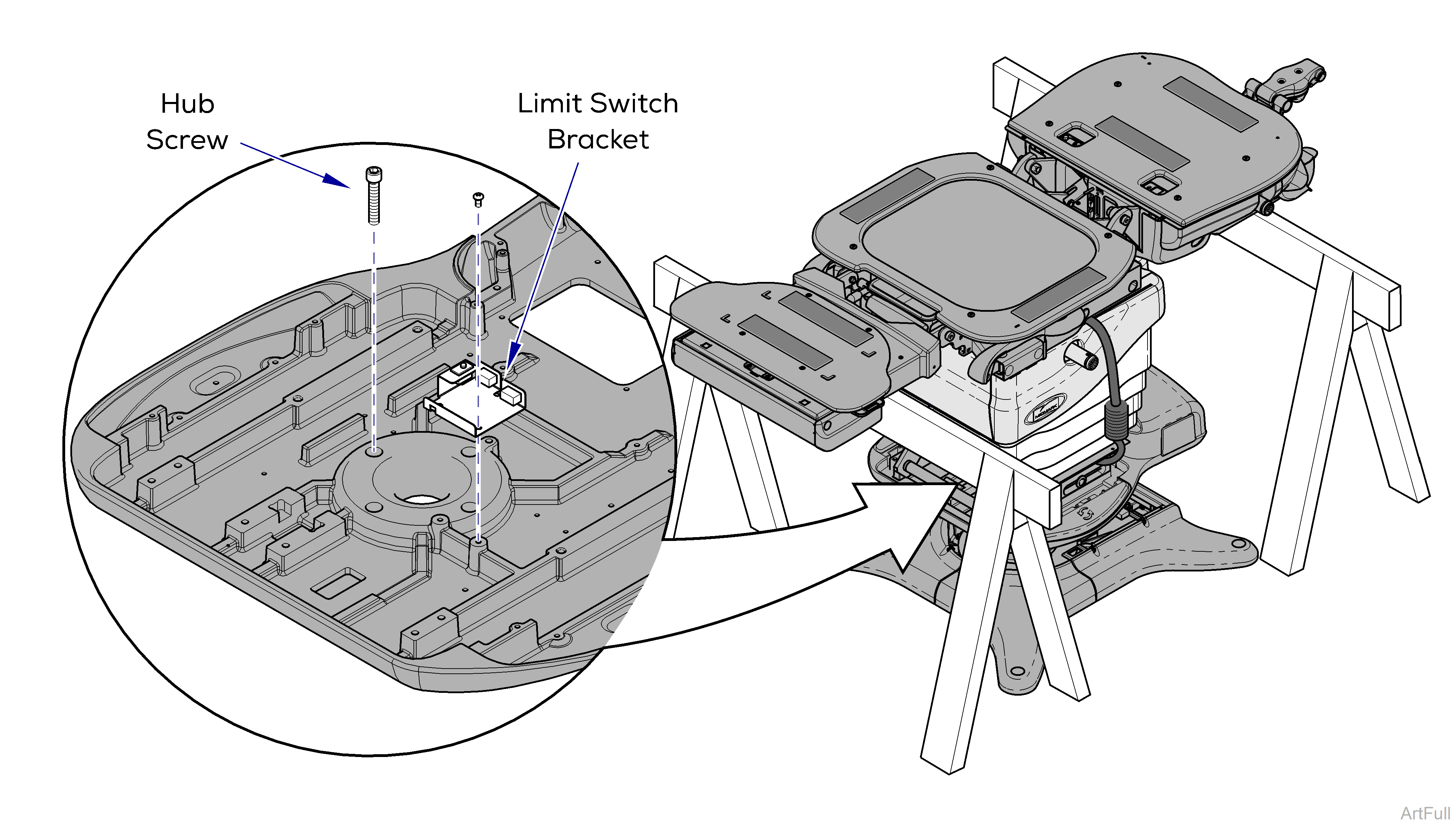
5.Remove two screws from limit switch bracket.
6.Move limit switch bracket to access hub screws.
Be careful not to put stress on wire harnesses when performing next two steps.
7.Remove four hub screws from upper base casting.
8.Press Base Down on hand / foot control to separate the upper base casting from the lower base casting.
Disconnect the chair power cord before performing steps 9 thru 14.
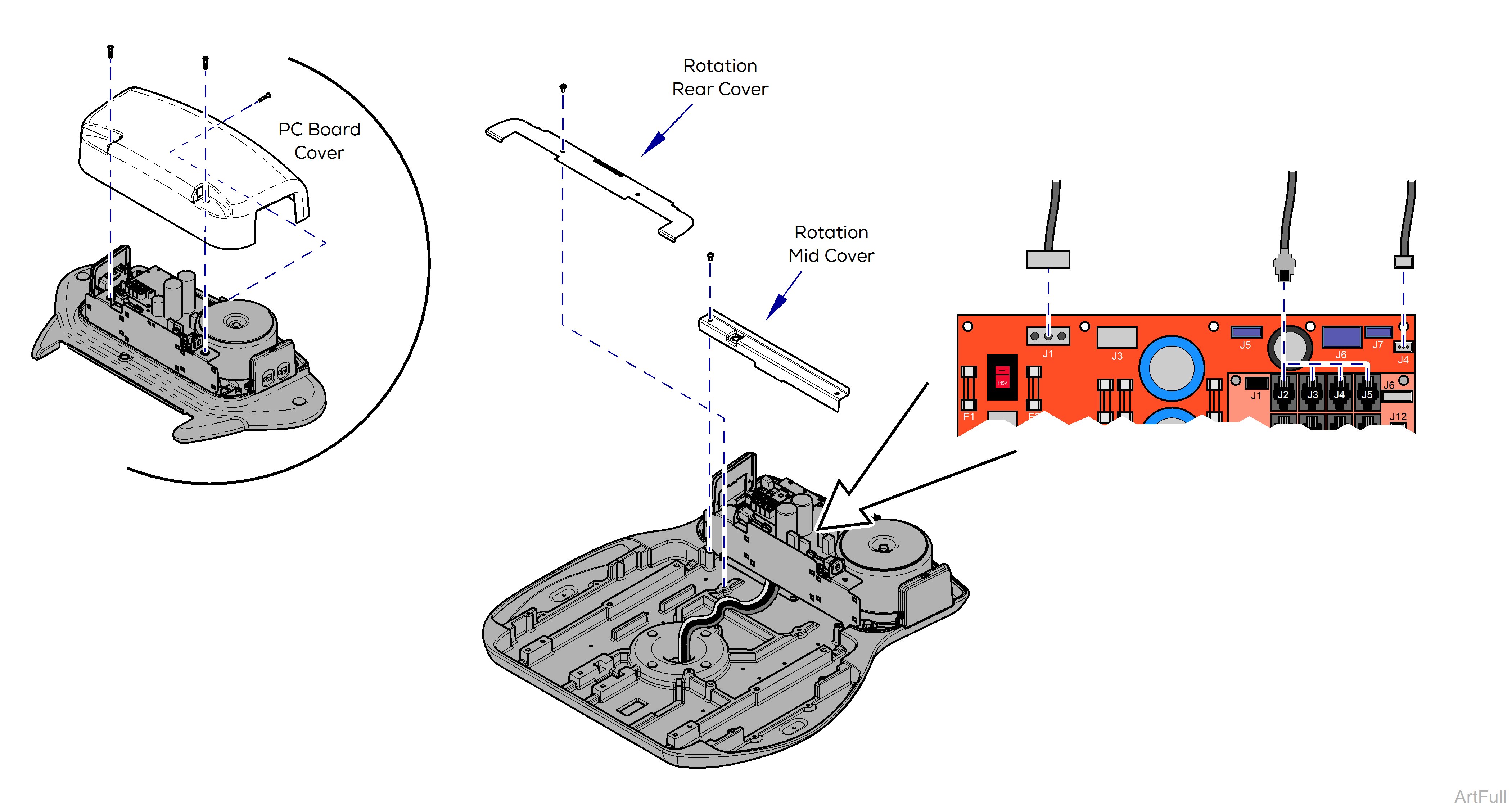
9.Remove three screws and PC Board cover.
10.Remove two screws and rotation mid cover.
11.Remove two screws and rotation rear cover.
12.Disconnect wire connections J1 and J4 from Power Supply PC Board.
13.Disconnect wire connection J2 from Machine Control PC Board.
14.Disconnect Ground wire from upper base casting (Not Shown).
J2 thru J8 on Machine Control PC Board are interchangeable.
The steps on this page require power to be connected to the chair. Avoid all contact with wiring and electrical components.
The wire connections and wire routing must be put back in original locations.
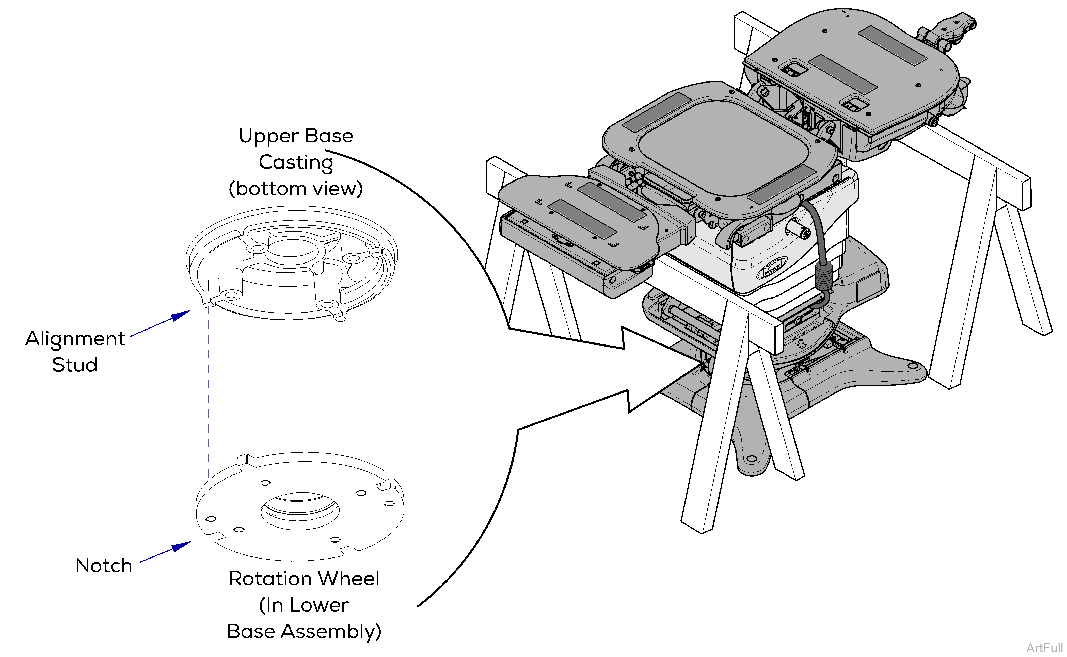
15.Connect and secure wire connections.
16.Carefully adjust chair top until alignment studs on bottom of upper casting lock into the notches in the rotation wheel.
You will feel the chair drop into place when alignment studs engage notches.
Disconnect the chair power cord before performing the remaining assembly.
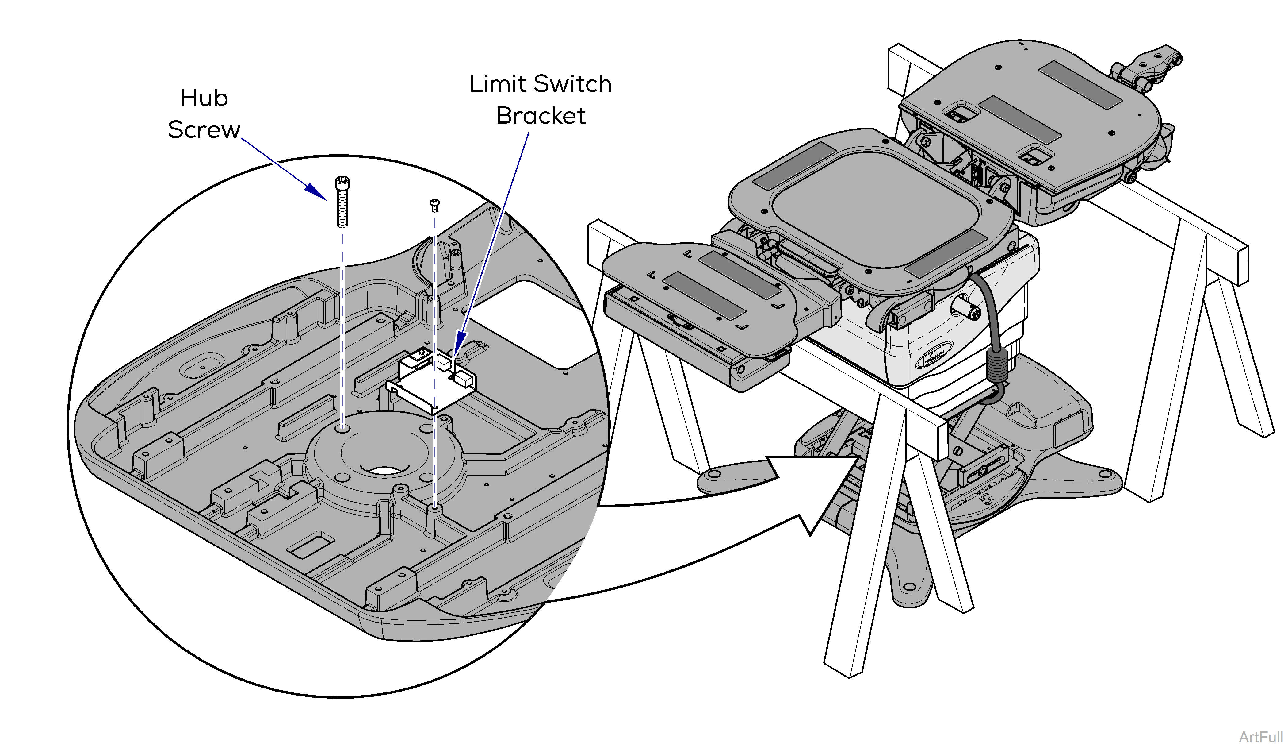
17. Install four hub screws and limit switch bracket.
Follow steps in reverse to complete assembly.

