641 Chair Power To The Tables w/ Standard Base Troubleshooting
|
Model |
641 -002 and -003 |
| Serial Number | All |
This illustration shows only the components that affect all table functions. Refer to the following page for a detailed description of the power supply to the table.
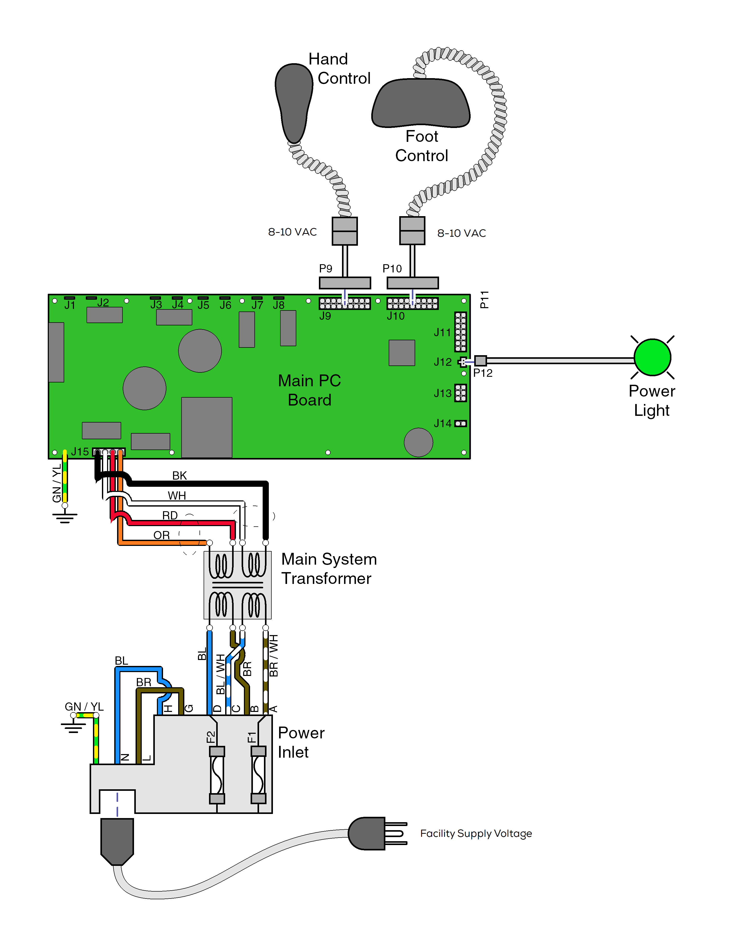
•If Power Light is off, there is no power to PC Board. If Power Light is On, proper voltage is present at PC Board.
•Black and white wires supply 48-54 VAC to power circuitry for the Base and Back actuators.
•Red and orange wires supply 34-37 VAC to power circuitry for the Tilt and Foot actuators, hand/foot controls, power light, all limit switches, and position sensors.
With the table's power cord properly connected, facility supply voltage (115 or 230 VAC) is supplied thru the cord to the power inlet.
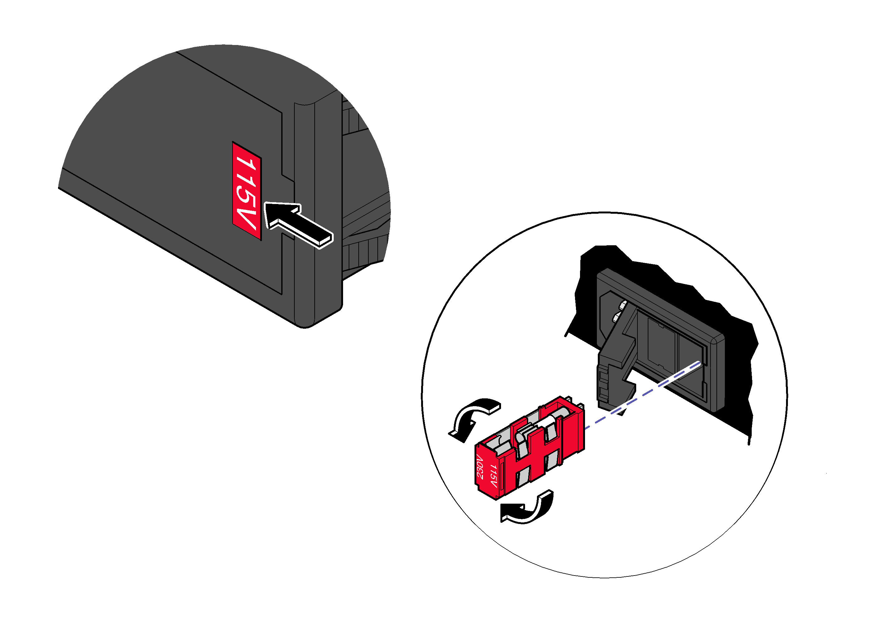
The voltage setting displayed in the power inlet window must match facility supply voltage (115 or 230 VAC). Remove fuse holder and rotate 180° to change voltage setting.
Current flows thru two fuses in the power inlet, to the main system transformer.
This transformer is protected from overload by a thermal cutout feature. This will automatically reset when the transformer cools.
Line voltage of 115 or 230 VAC is supplied to the main system transformer. The transformer reduces the voltage and current flows to the main PC board thru two separate windings - four wires.
The black and white wires supply 48-54 VAC to power circuitry for the Base and Back actuators only. The red and orange wires supply 34-37 VAC to power circuitry for the Tilt and Foot actuators, hand/foot controls, power light, all limit switches, and position sensors - on Midmark models only.
When voltage is applied to the PC board, the power light is illuminated.
Circuitry on the PC board provides the required voltage to power all of the table's components: hand/foot controls, actuators, limit switches, and position sensors.
Circuitry on the main PC board supplies 8-10 VAC to the hand / foot control connection ports.
