646 Chair Back Up / Down Function Troubleshooting
The illustrations show only the components / wiring that affect the Back Up / Down function.
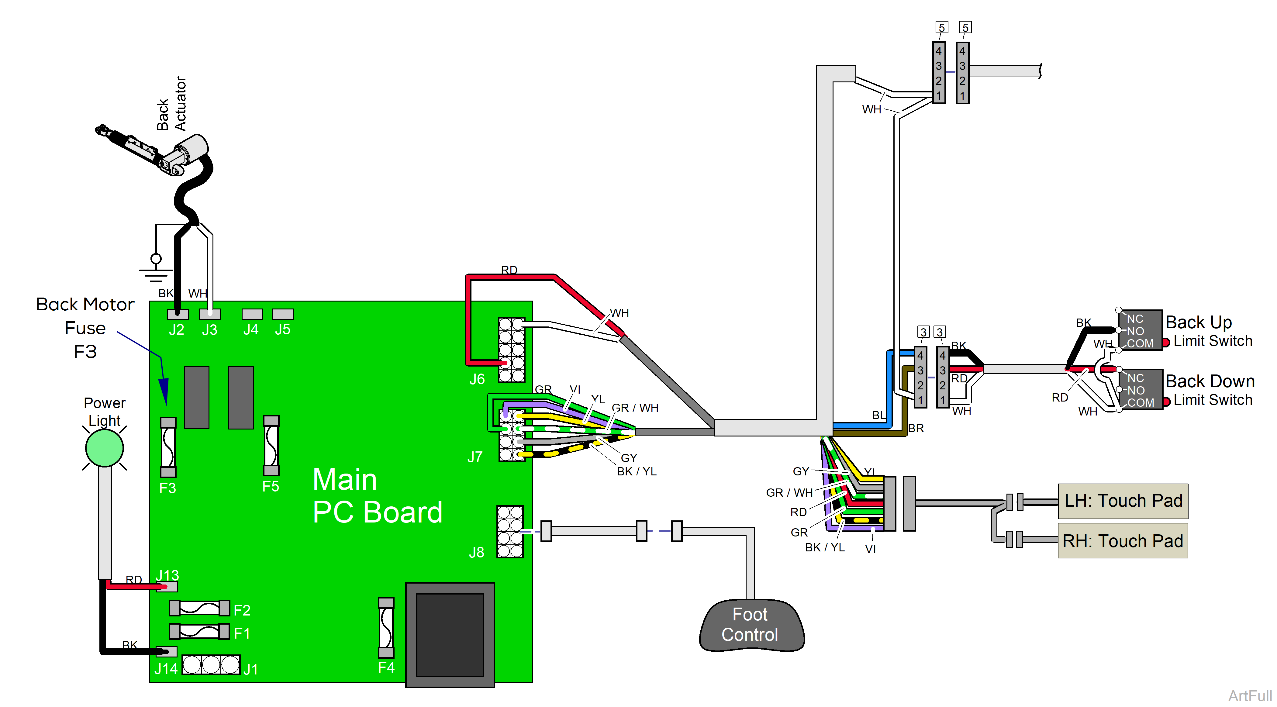
Refer to: Crash Avoidance System for a detailed description of "crash position", and the functions that are disabled.
When voltage is applied to the PC board, the power light is illuminated.
When voltage is present at the PC board, the power light is illuminated. Refer to: Power to the Chair for description of current flow to the PC board.
Circuitry on the PC board supplies 14 VAC to the foot control and touch pads.
When the Back Up function is activated, current flows thru the foot control / touch pad back to the main PC board. Circuitry on the main PC board supplies approximately 48 VDC to the back actuator motor.
The actuator motor runs and raises the back section.
The main PC board continuously monitors the back up limit switch. If the back up limit switch is tripped (closed), the Back Up function will not operate.
Actuator motor runs until:
1.Foot control / touch pad button is released.
2.Back Up limit switch is tripped.
3.Overcurrent protection tripped.
4.Software timeout is reached (30 seconds).
When the Back Down function is activated, current flows thru the foot control / touch pad back to the main PC board. Circuitry on the main PC board supplies approximately 44 VDC to the back actuator motor.
The actuator motor runs and lowers the back section.
The main PC board continuously monitors the back down limit switch. If the back down limit switch is tripped (open), the Back Down function will not operate.
Actuator motor runs until:
1.Foot control / touch pad button is released.
2.Back Down limit switch is tripped.
3.Emergency Stop button is pressed.
4.Overcurrent protection tripped
5.Software timeout is reached (30 seconds).
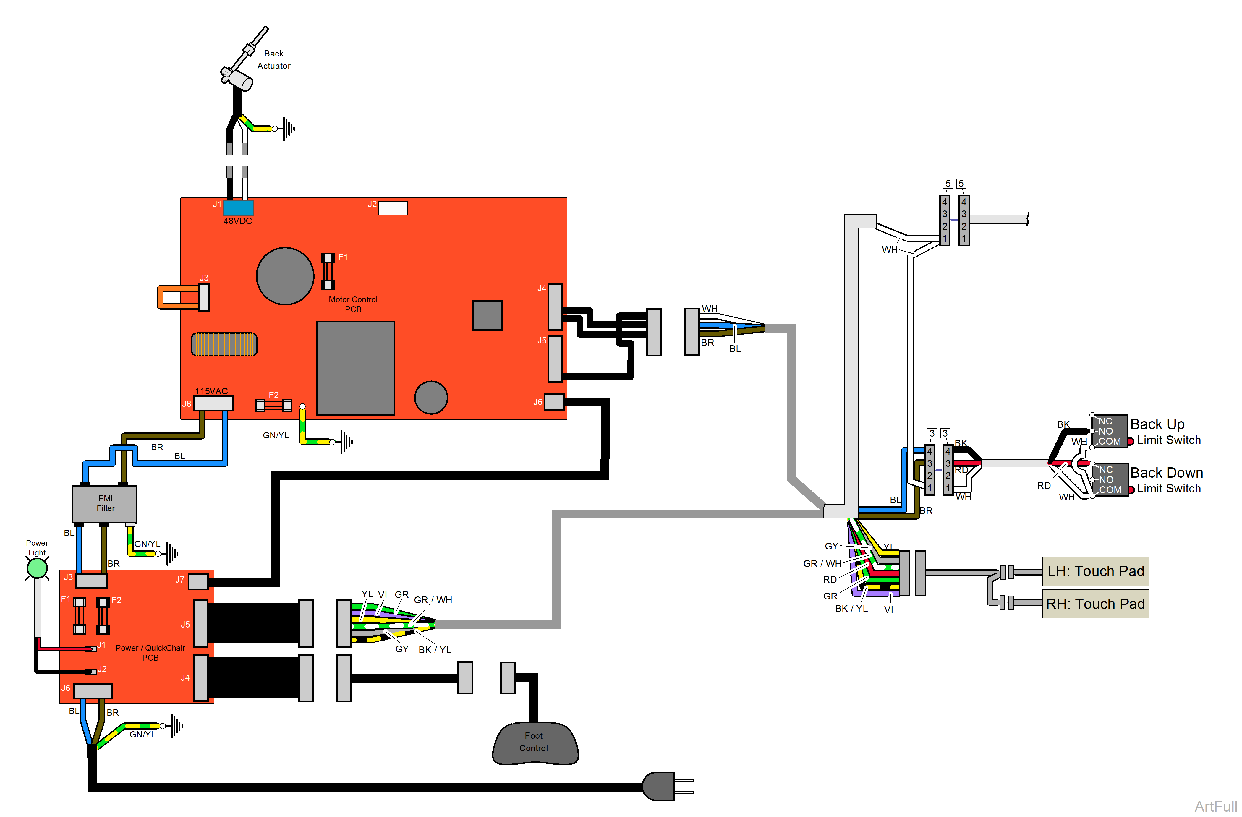
Refer to: Crash Avoidance System for a detailed description of "crash position", and the functions that are disabled.
When voltage is present at the Power / Quick Chair PC board the power light is illuminated. Refer to: Power to the Chair for description of current flow to the PC Board.
Circuitry on the Motor Control PC board supplies 3.3 VDC to the foot control and touch pads.
When the Back Up function is activated, current flows thru the foot control / touch pad back to the Motor Control PC board. Circuitry on the Motor Control PC board supplies approximately 48 VDC to the back actuator motor.
The actuator motor runs and raises the back section.
The Motor Control PC board continuously monitors the back up limit switch. If the back up limit switch is tripped (closed), the Back Up function will not operate.
Actuator motor runs until:
1.Foot control / touch pad button is released.
2.Back Up limit switch is tripped.
3.Emergency Stop button is pressed.
4.Overcurrent protection tripped.
5.Software timeout is reached (30 seconds).
When the Back Down function is activated, current flows thru the foot control / touch pad back to the Motor Control PC board. Circuitry on the Motor Control PC board supplies approximately 48 VDC to the back actuator motor.
The actuator motor runs and lowers the back section.
The Motor Control PC board continuously monitors the back down limit switch. If the back down limit switch is tripped (open), the Back Down function will not operate.
Actuator motor runs until:
1.Foot control / touch pad button is released.
2.Back Down limit switch is tripped.
3.Emergency Stop button is pressed.
4.Overcurrent protection tripped.
5.Software timeout is reached (30 seconds).
