646 Chair Back Actuator / Limit Switch Test and Repair
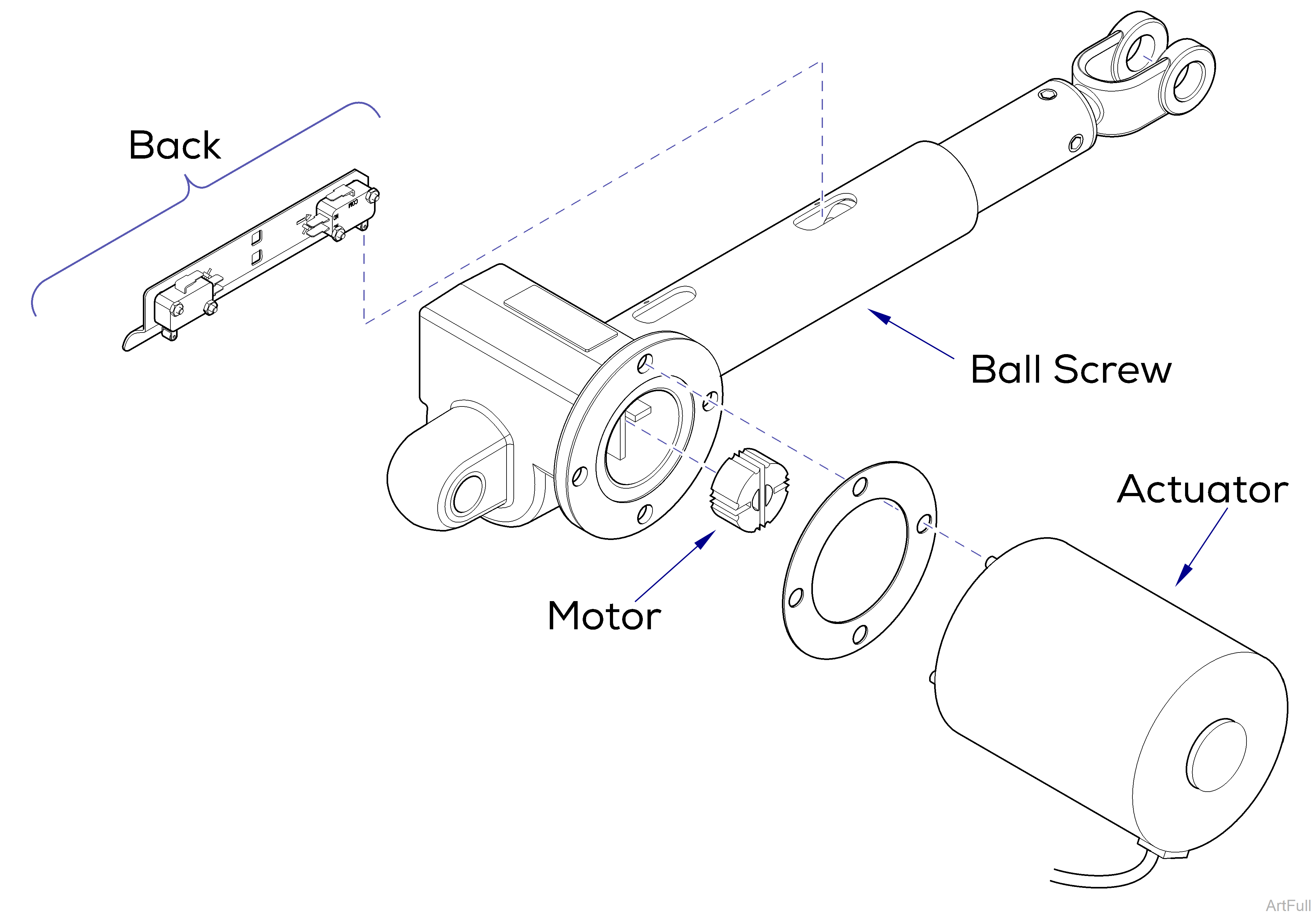
This illustration shows the back limit switches and the three serviceable components of the back actuator. Use the table below to isolate the malfunction.
Do not adjust the individual switches! The limit switches and bracket must be replaced as a complete assembly.
| Problem |
Required Action |
|---|---|
|
Motor runs, but makes grinding noise. |
Clean / lube actuator threads. Replace actuator if necessary. |
|
Motor runs, but table does not move. |
Inspect / replace motor coupler. |
|
Motor does not run. |
Perform Limit Switch / PC Board Harness Test. |
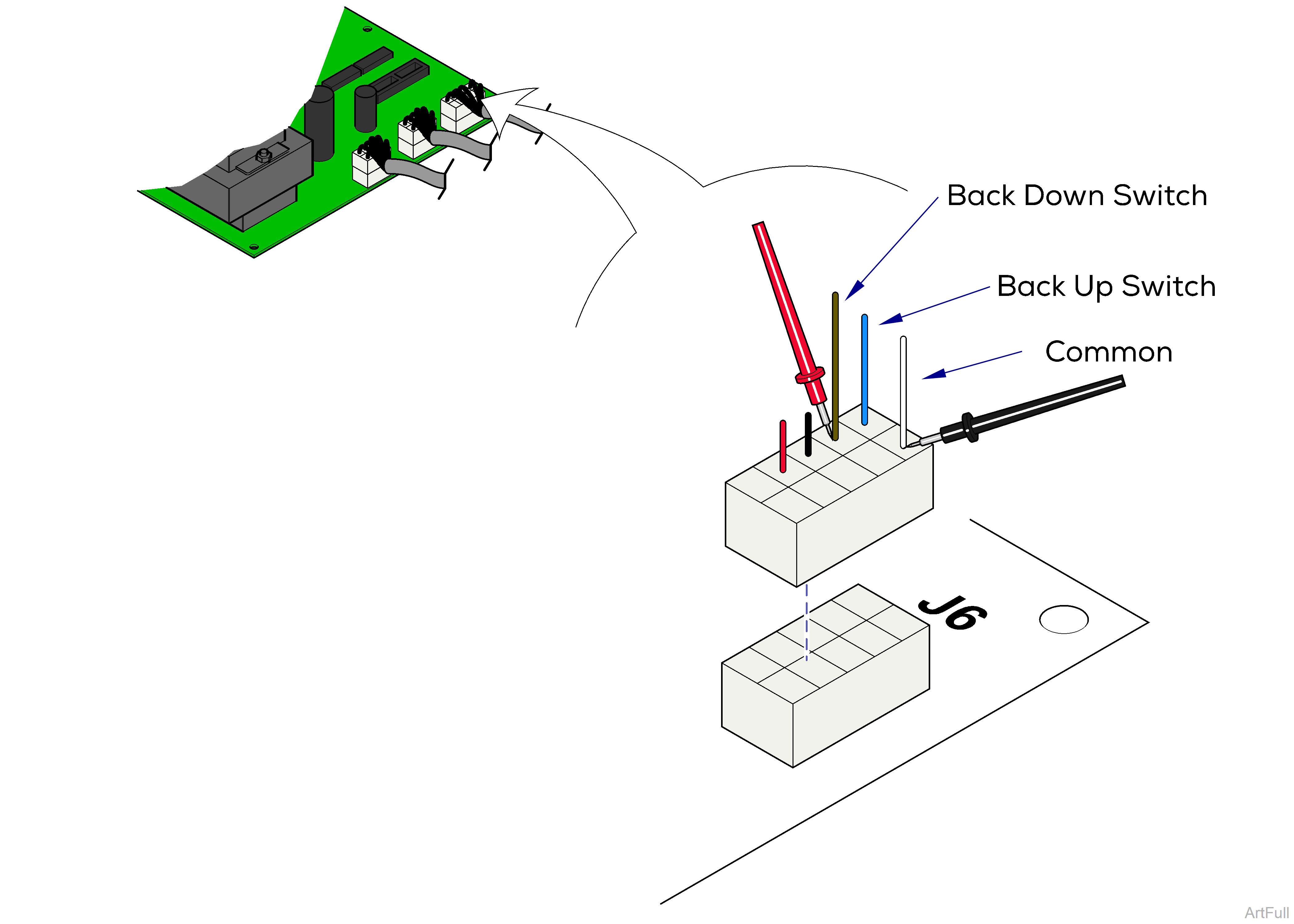
1.Disconnect harnesses from J6 on main PC board.
2.Place one meter probe on the common (white).
3.Place other probe on the wire corresponding the desired switch (see illustration).
Check switch tripped and untripped.
|
Meter Reading |
Required Action |
|---|---|
|
OL |
Limit switch / harness OK Perform Actuator Motor Test |
|
Less than 10 ohms |
Perform Limit Switch Harness Test |
|
Meter Reading |
Required Action |
|---|---|
|
OL |
Perform Limit Switch Harness Test |
|
Less than 10 ohms |
Limit switch / harness OK Perform Actuator Harness Test |
1.Unplug the appropriate limit switch harness.
2.Measure continuity.
|
Actuator Position |
Meter Reading Should Be |
|---|---|
|
Actuator Full Up |
White to Black - Open |
|
Actuator Full Down |
White to Black - Closed |
|
Actuator Midway Point |
White to Black - Closed |
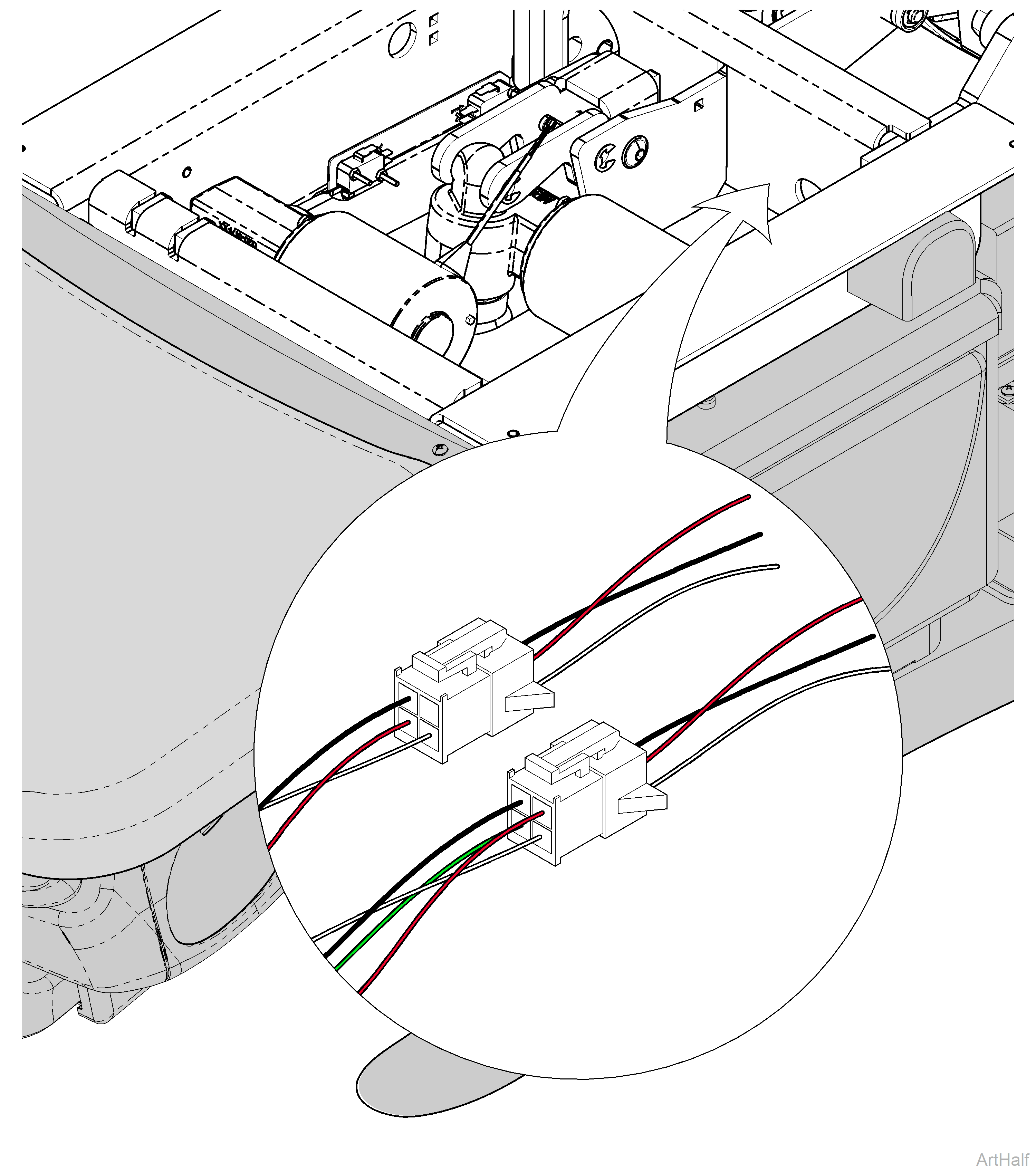
1.Tag and disconnect back actuator wires (J2 and J3).
2.Place meter probes on actuator wires. Check meter reading.
|
Meter Reading |
Required Action |
|---|---|
|
1 to 10 ohms |
Actuator motor OK Perform Motor Ground Test |
|
OL or less than 1 ohms |
Replace actuator motor |
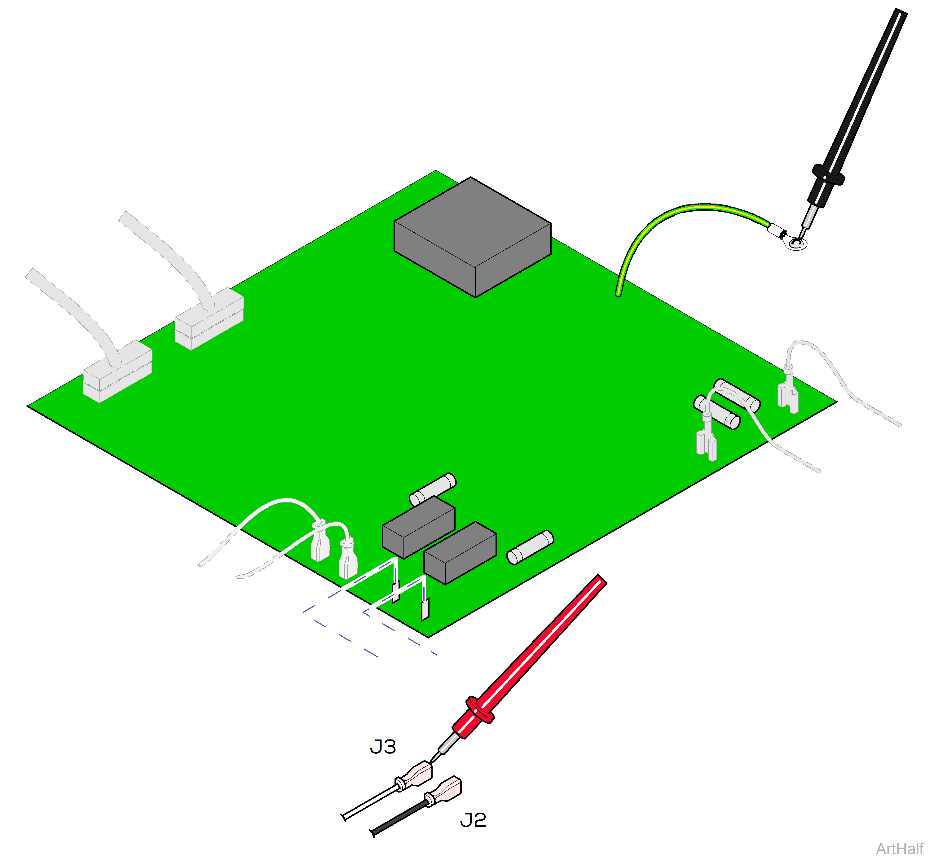
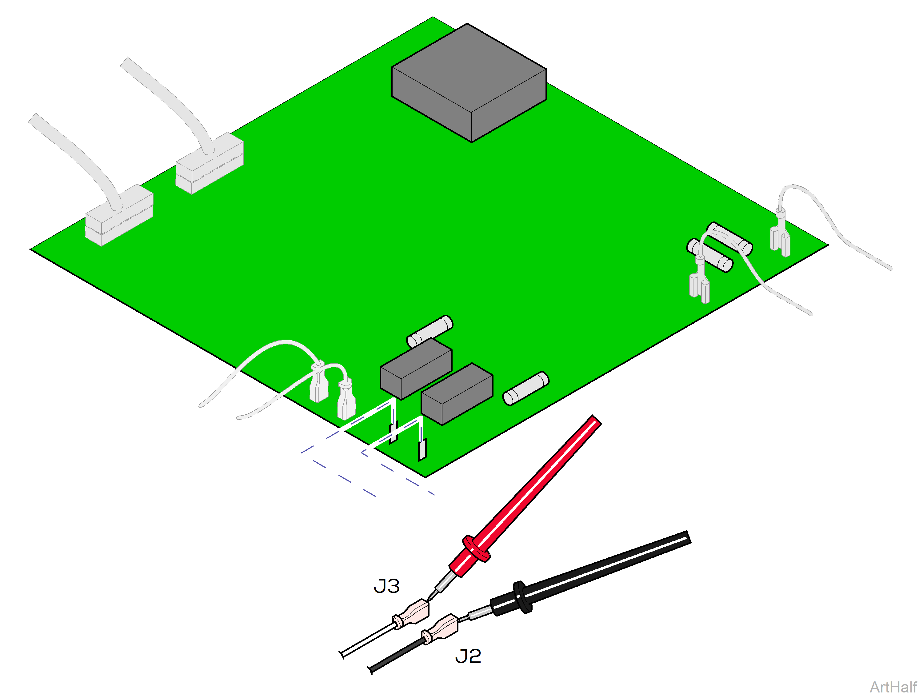
1.Place one meter probe on actuator wire (J3).
2.Place other meter probe on PC board ground wire.
3.Check meter reading.
4.Repeat steps for J2 wire.
|
Meter Reading |
Required Action |
|---|---|
|
OL or more than 1 mega-ohm |
Motor harness OK Perform PC Board Test |
|
Less than 1 ohm |
Replace actuator motor |
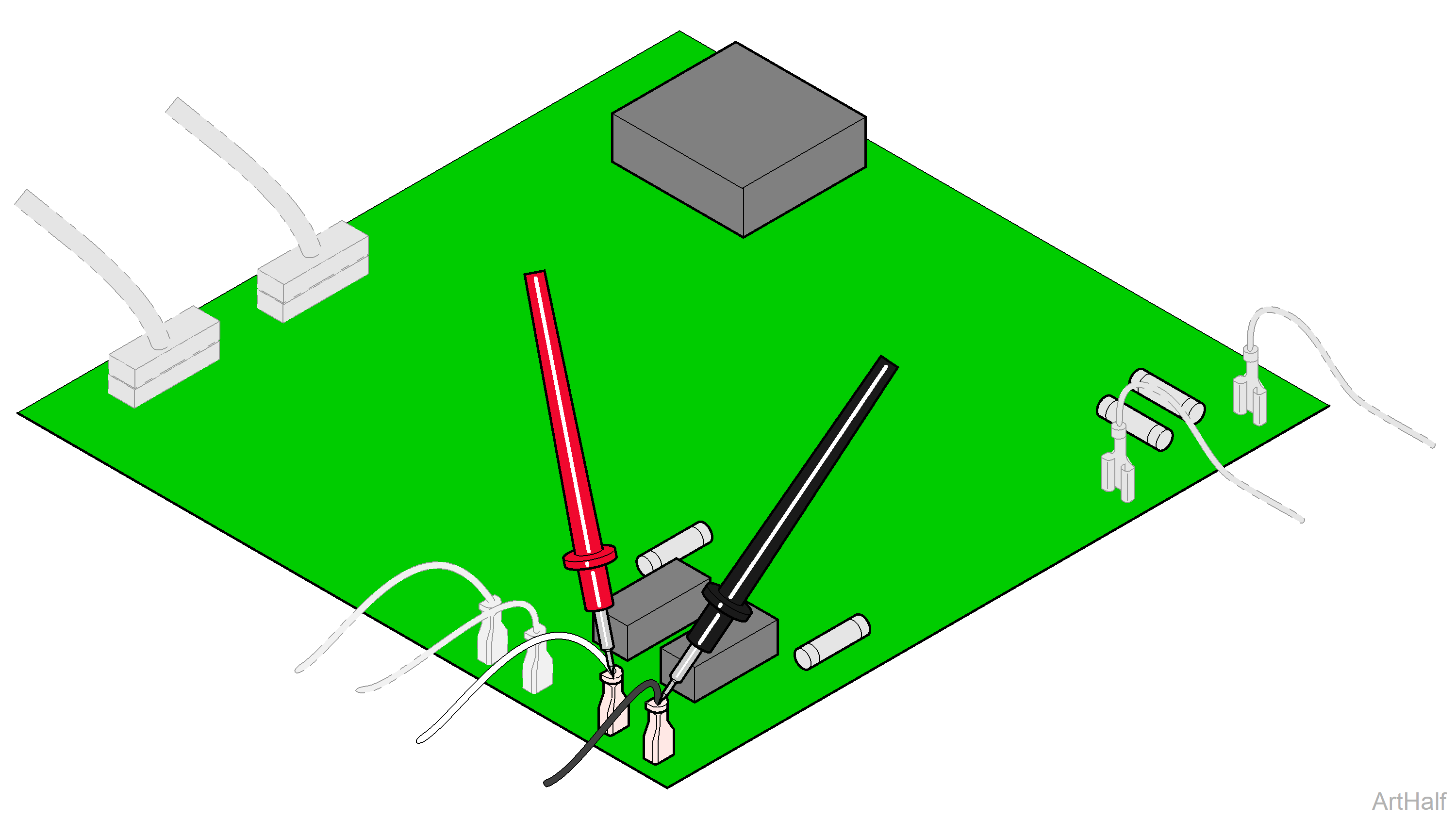
1.Place meter probes on wires at J2 and J3 terminals.
2.Check meter reading while activating Back Up / Back Down function with foot control.
|
Meter Reading |
Required Action |
|---|---|
|
Approximately 48 VDC |
PC board OK |
|
0 VDC |
Replace PC Board |
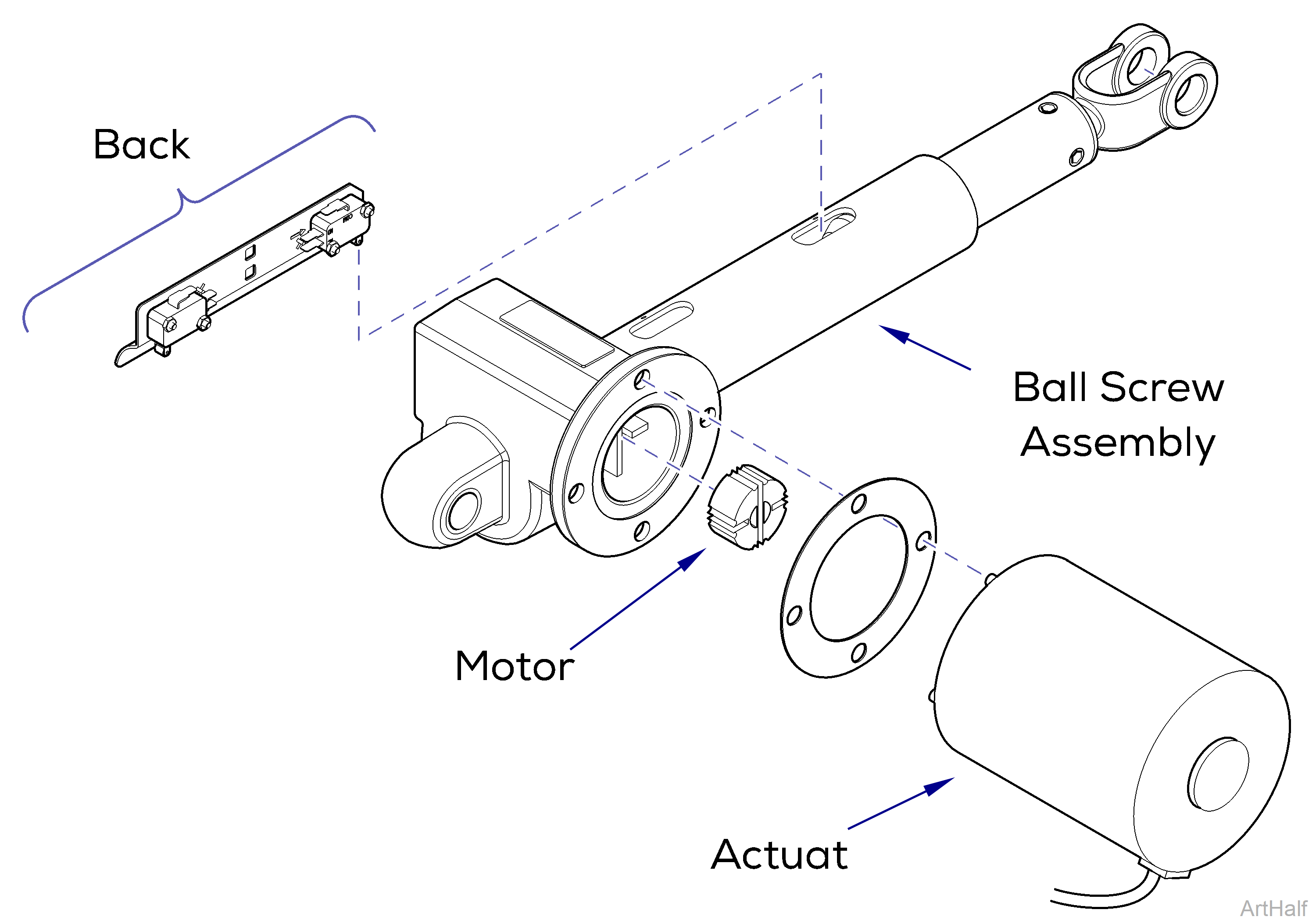
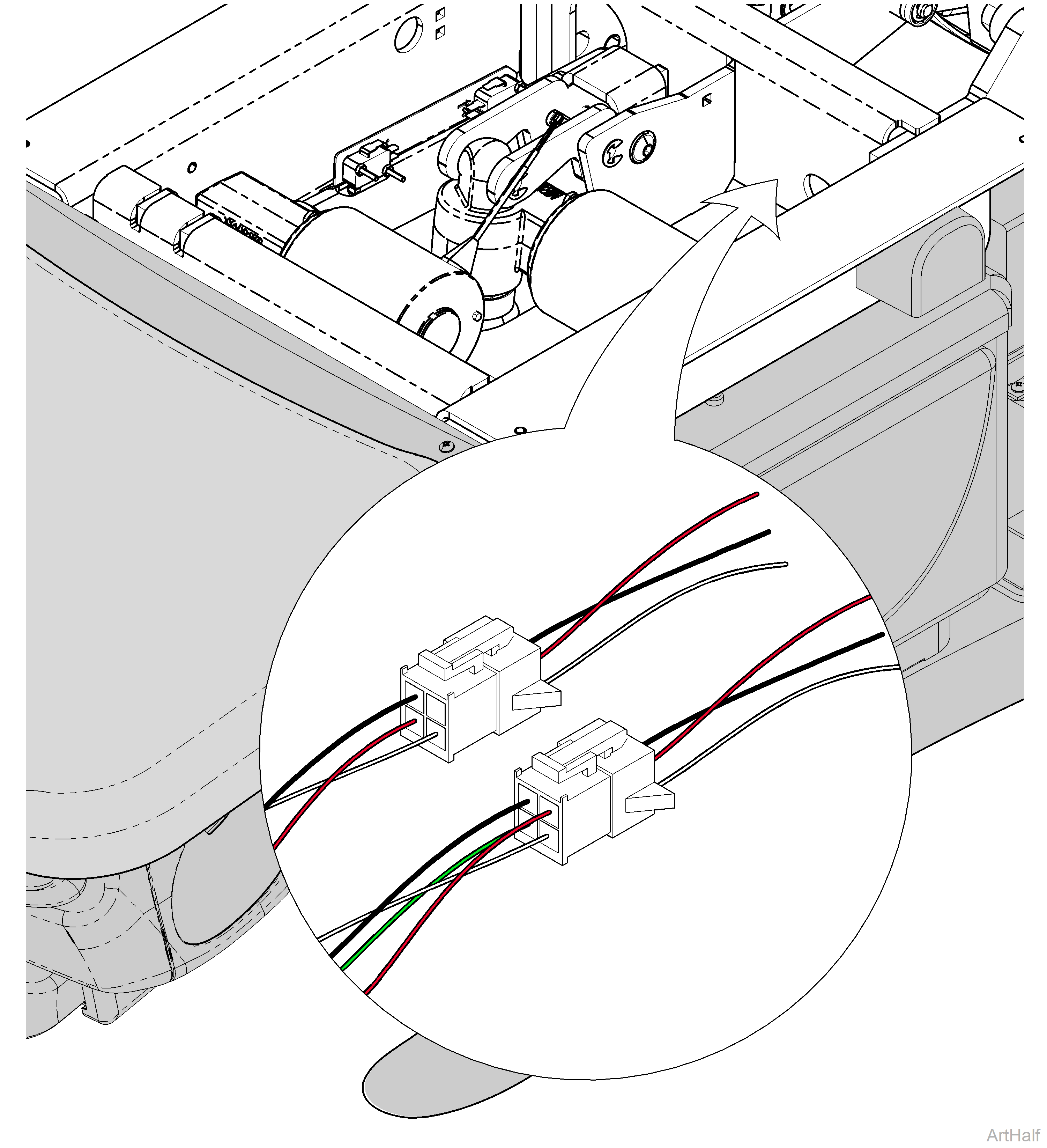
This illustration shows the back limit switches and the three serviceable components of the back actuator. Use the table below to isolate the malfunction.
Do not adjust the individual switches! The limit switches and bracket must be replaced as a complete assembly.
| Problem |
Required Action |
|---|---|
|
Motor runs, but makes grinding noise. |
Clean / lube actuator threads. Replace actuator if necessary. |
|
Motor runs, but table does not move. |
Inspect / replace motor coupler. |
|
Motor does not run. |
Perform Limit Switch / PC Board Harness Test. |
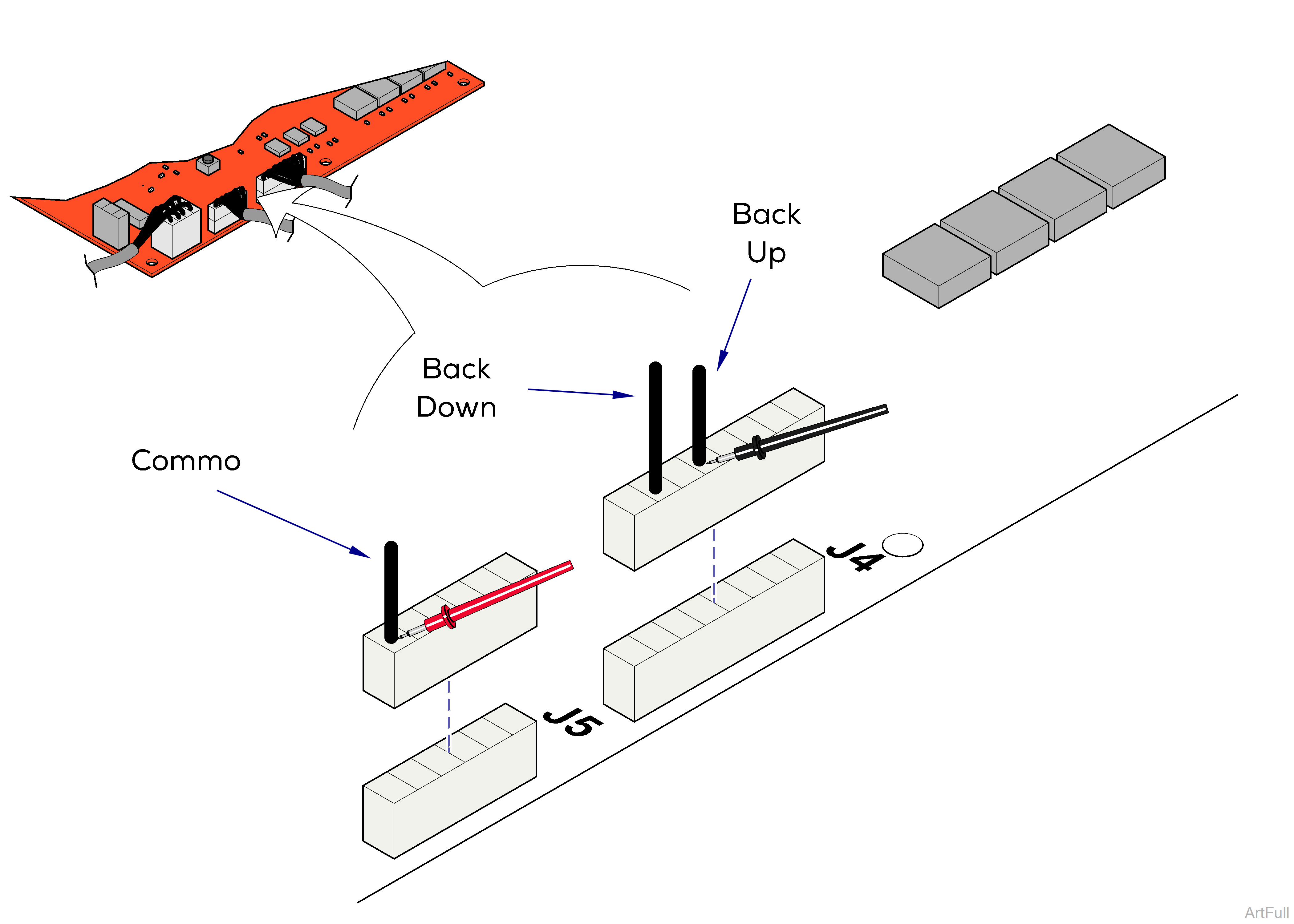
1.Disconnect harnesses from J4 and J5 on Motor Control PC board.
2.Place one meter probe on the common wire.
3.Place other probe on the wire corresponding the desired switch (see illustration).
Check switch tripped and untripped.
|
Meter Reading |
Required Action |
|---|---|
|
OL |
Limit switch / harness OK Perform Actuator Motor Test |
|
Less than 10 ohms |
Perform Limit Switch Harness Test |
|
Meter Reading |
Required Action |
|---|---|
|
OL |
Limit switch / harness OK Perform Actuator Harness Test |
|
Less than 10 ohms |
Perform Limit Switch Harness Test |
|
Meter Reading |
Required Action |
|---|---|
|
OL |
Perform Limit switch Harness Test |
|
Less than 10 ohms |
Limit switch / harness OK Perform Actuator Motor Test |
1.Unplug the appropriate limit switch harness.
2.Measure continuity.
|
Actuator Position |
Meter Reading Should Be |
|---|---|
|
Actuator Full Up |
White to Black - Open |
|
Actuator Full Down |
White to Black - Closed |
|
Actuator Midway Point |
White to Black - Closed |
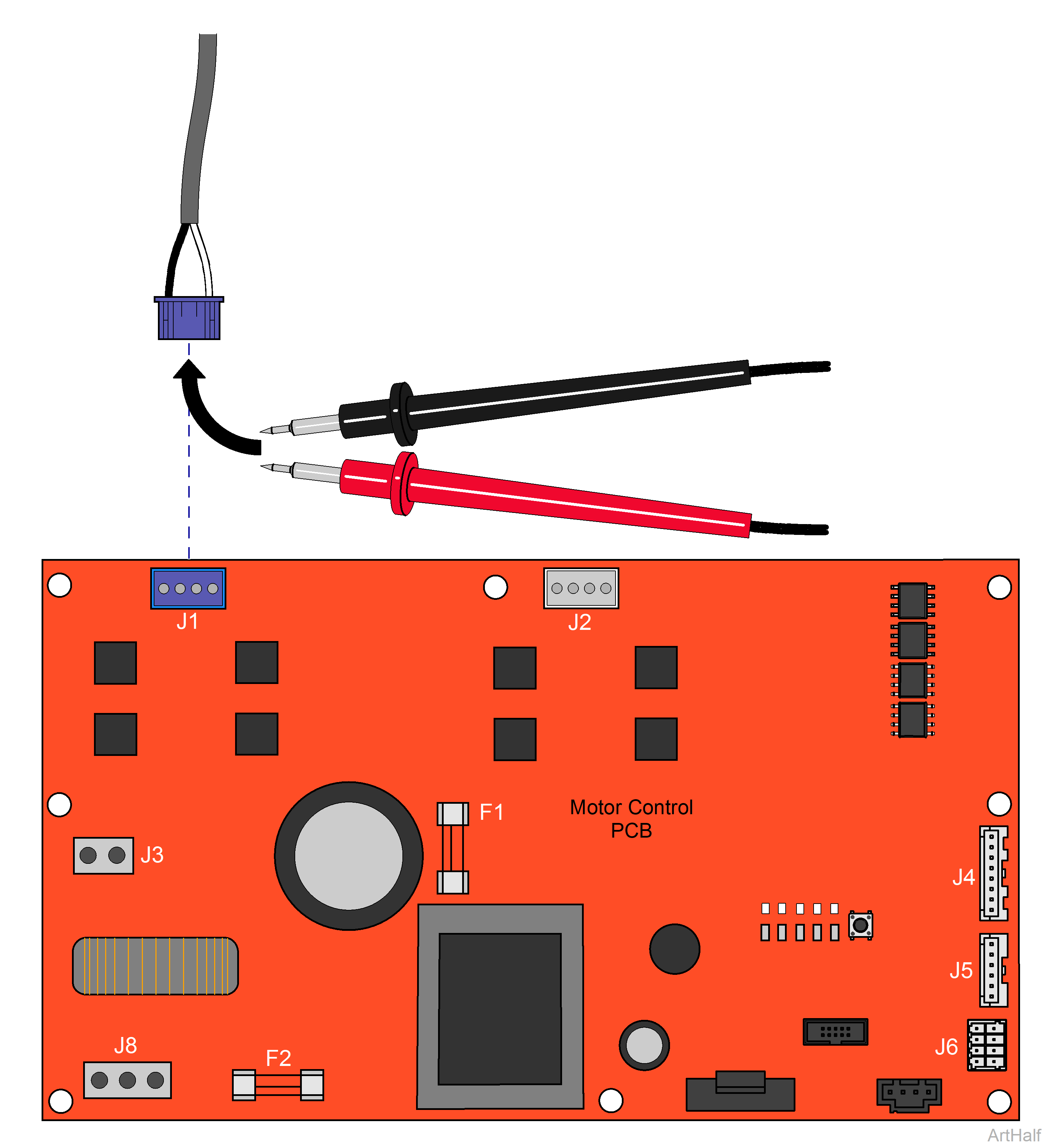
1.Disconnect power to the chair.
2.Disconnect Back actuator from J1 on PC Board.
3.Set multimeter to Ohms to check resistance.
4.Using a multimeter, place meter probes on actuator wires.
|
Meter Reading |
Required Action |
|---|---|
|
1 to 10 ohms |
Actuator motor OK Perform Motor Ground Test |
|
OL or less than 1 ohms |
Replace actuator motor |
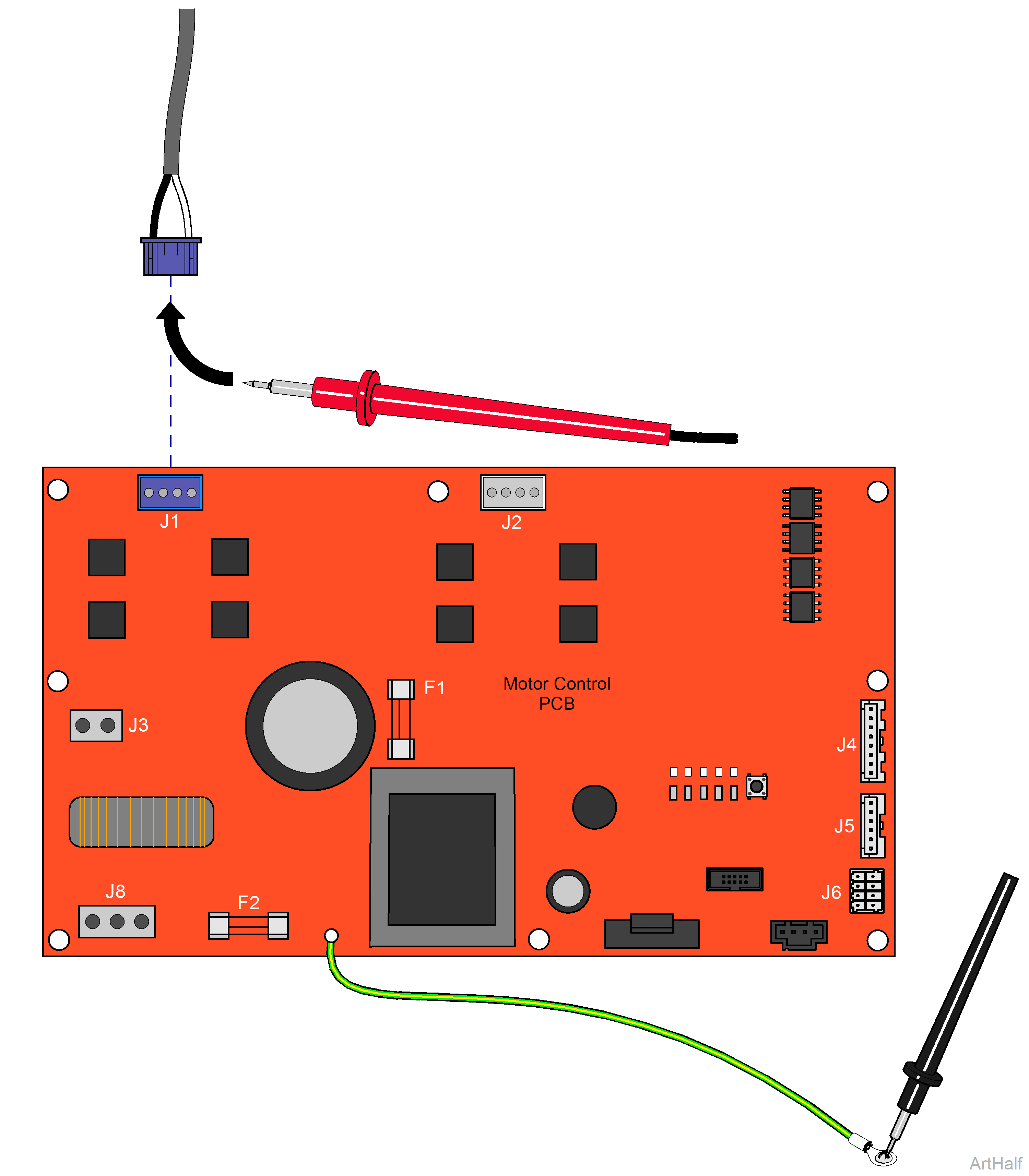
1.Place one meter probe on actuator Black wire (J1).
2.Place other meter probe on PC board ground wire.
3.Check meter reading.
4.Repeat steps for White wire.
|
Meter Reading |
Required Action |
|---|---|
|
OL or more than 1 mega-ohm |
Motor harness OK Perform PC Board Test |
|
Less than 1 ohm |
Replace actuator motor |
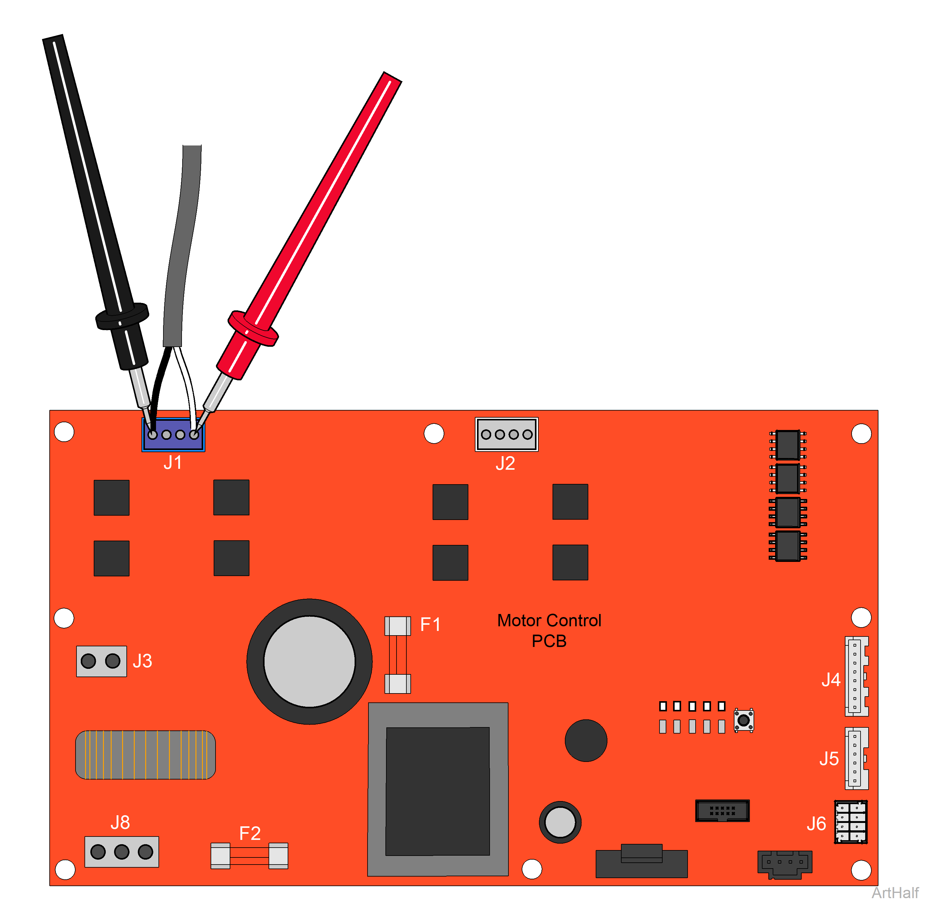
1.Place meter probes on Black and White wires at J1 on Motor Control PC board.
2.Check meter reading while activating Back Up / Back Down function with foot control.
|
Direction |
Meter Reading |
Required Action |
|---|---|---|
|
Back Up |
Approximately 48 VDC |
PC board OK |
|
Any Direction |
0 VDC |
Replace PC Board |
|
Back Down |
Approximately 21 VDC |
PC board OK |
