647 Chair Rotational Base Brake System Troubleshooting
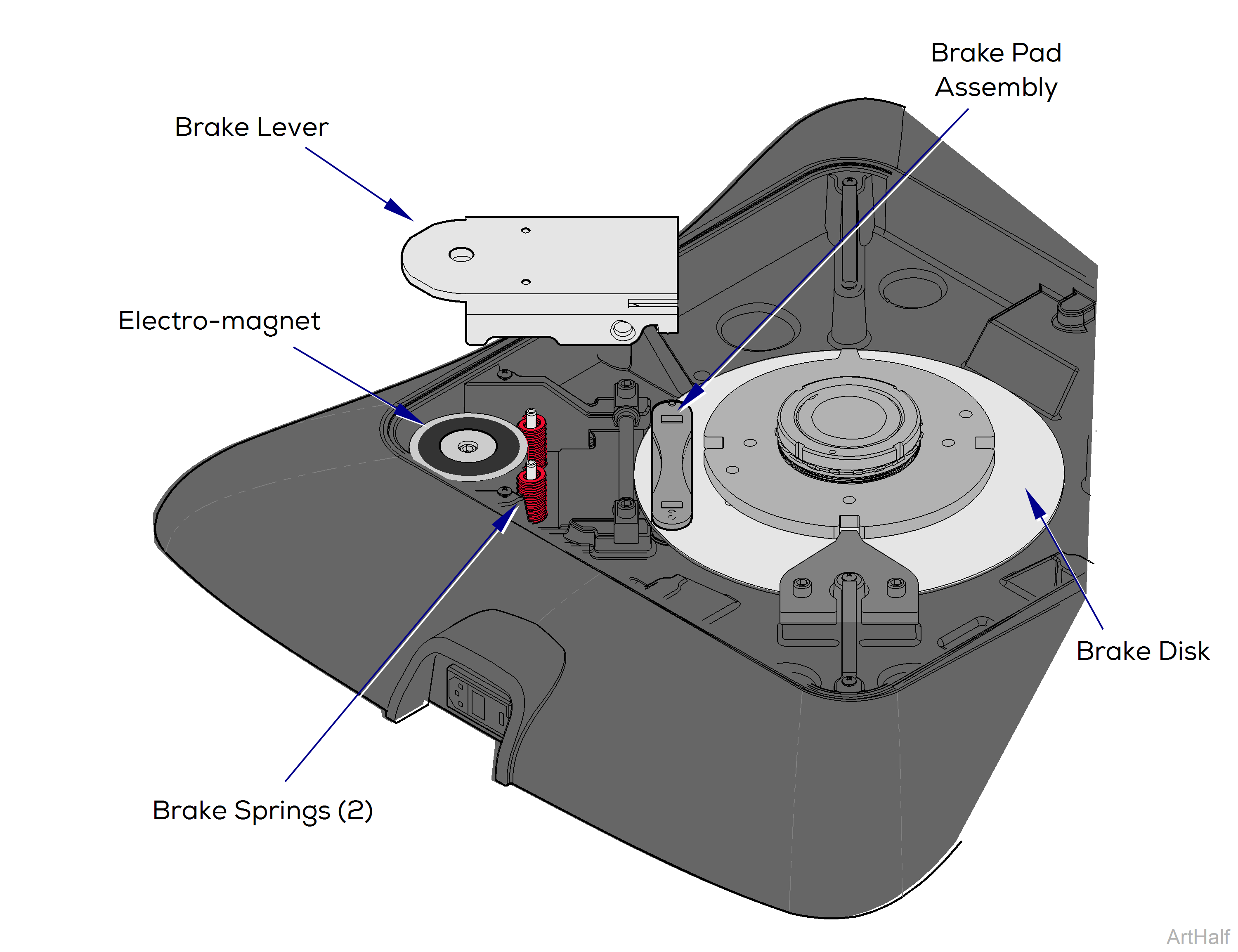
This illustration shows only the components that affect the Rotational Base Brake System. A detailed description of current flow also appears below.
Base Rotation Unlocked
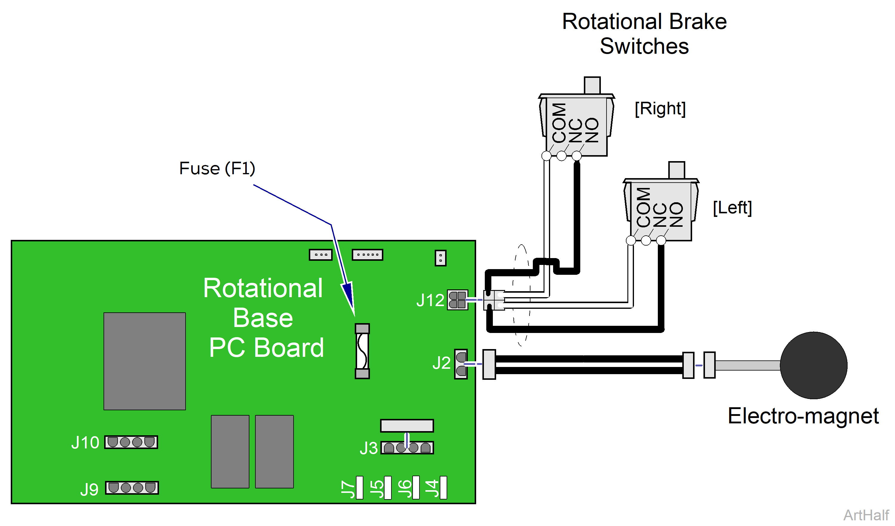
The rotational base PC board supplies 31-36 VAC to the two normally closed brake switches. When either brake pedal is pressed and released, the corresponding brake switch opens. When the open switch is detected, the PC board supplies approximately 15-20 VAC to the electro-magnet thru the F1 fuse.
When voltage is applied to the electro-magnet, the magnets pull overpowers the brake springs. This removes pressure from the brake pad assembly allowing the brake disk to rotate.
To lock base rotation, press and release either brake pedal.
Base automatically locks after two minutes
Base Rotation Locked
The two brake springs press upward on the brake lever. This pivots the brake lever so that pressure is applied to the brake pad assembly. This prevents the brake disk from rotating.
To unlock base rotation, press and release either brake pedal.
