647 Chair Rotational Base Brake System Test and Repair
|
Model |
647-003 and -004 |
| Serial Number | All |
|
Problem |
Required Action |
|---|---|
|
Brake will not lock
|
Unplug chair power cord. Does the brake lock? |
|
If YES, perform Rotational Brake Electrical Test. |
|
|
If NO, inspect the mechanical brake components. Refer to: Brake Lever / Electro-magnet Access below. |
|
|
Base wobbles when locked and/or grinding noise when base rotates
|
Without separating the castings, remove any debris between upper and lower castings. |
|
Inspect needle bearing and brake disk for damage. Tighten hub screws. |
|
|
Refer to: Separating Upper and lower base Castings below. |
|
|
Brake will not unlock
|
If one pedal works: Check faulty brake pedal switch. Refer to: Brake Pedal Switch Access below |
|
If neither brake pedal works: Perform Screwdriver Test. |
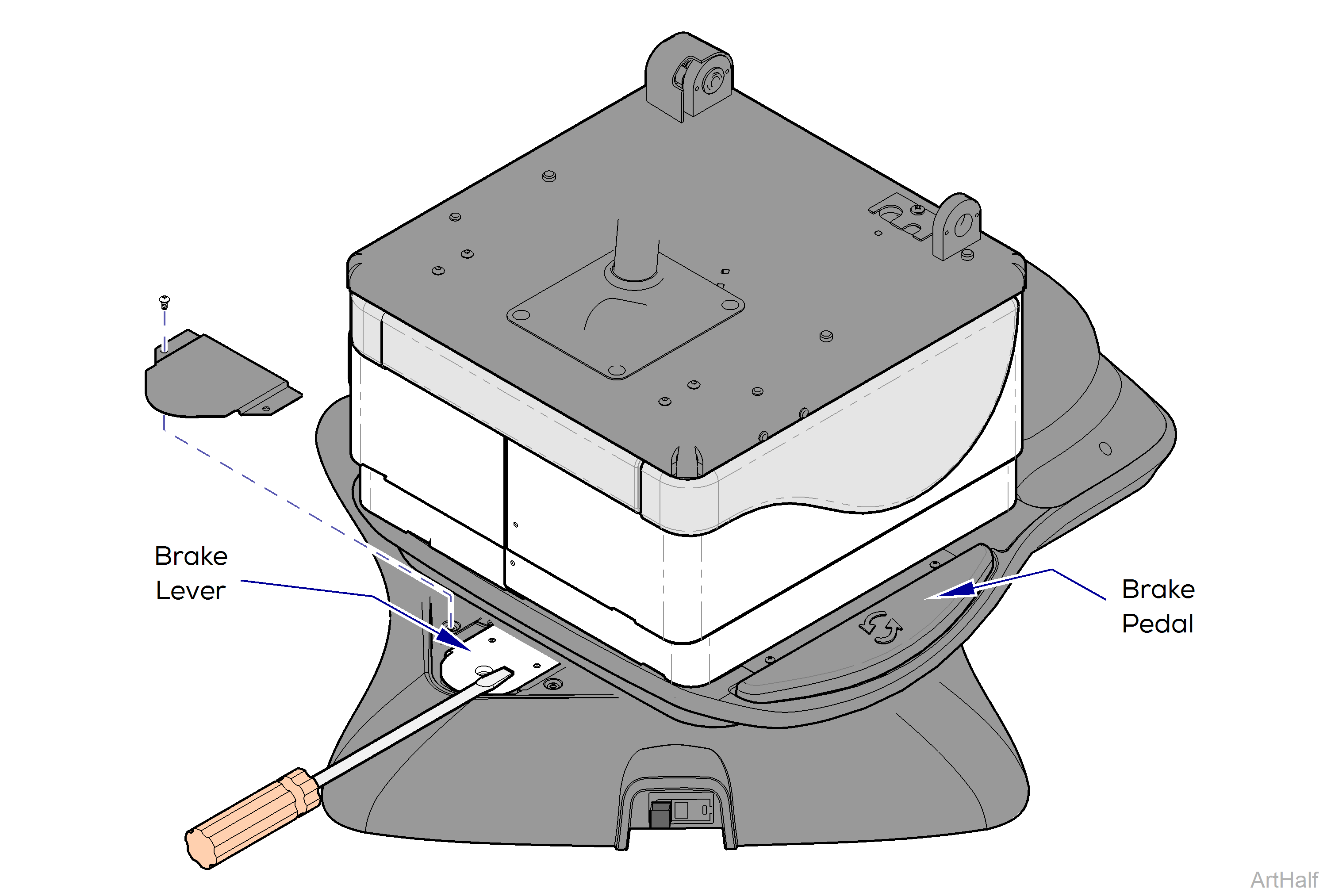
1.Remove brake lever cover. Hold a screwdriver on brake lever.
2.Press and release the brake pedal. Can you feel the electro-magnet energize? If YES Perform Magnet Position Adjustment. If NO Check rotational base PC board fuse. Perform Rotational Brake Electrical Test
If the rotational brake will not unlock, the electro-magnet may be out of adjustment.
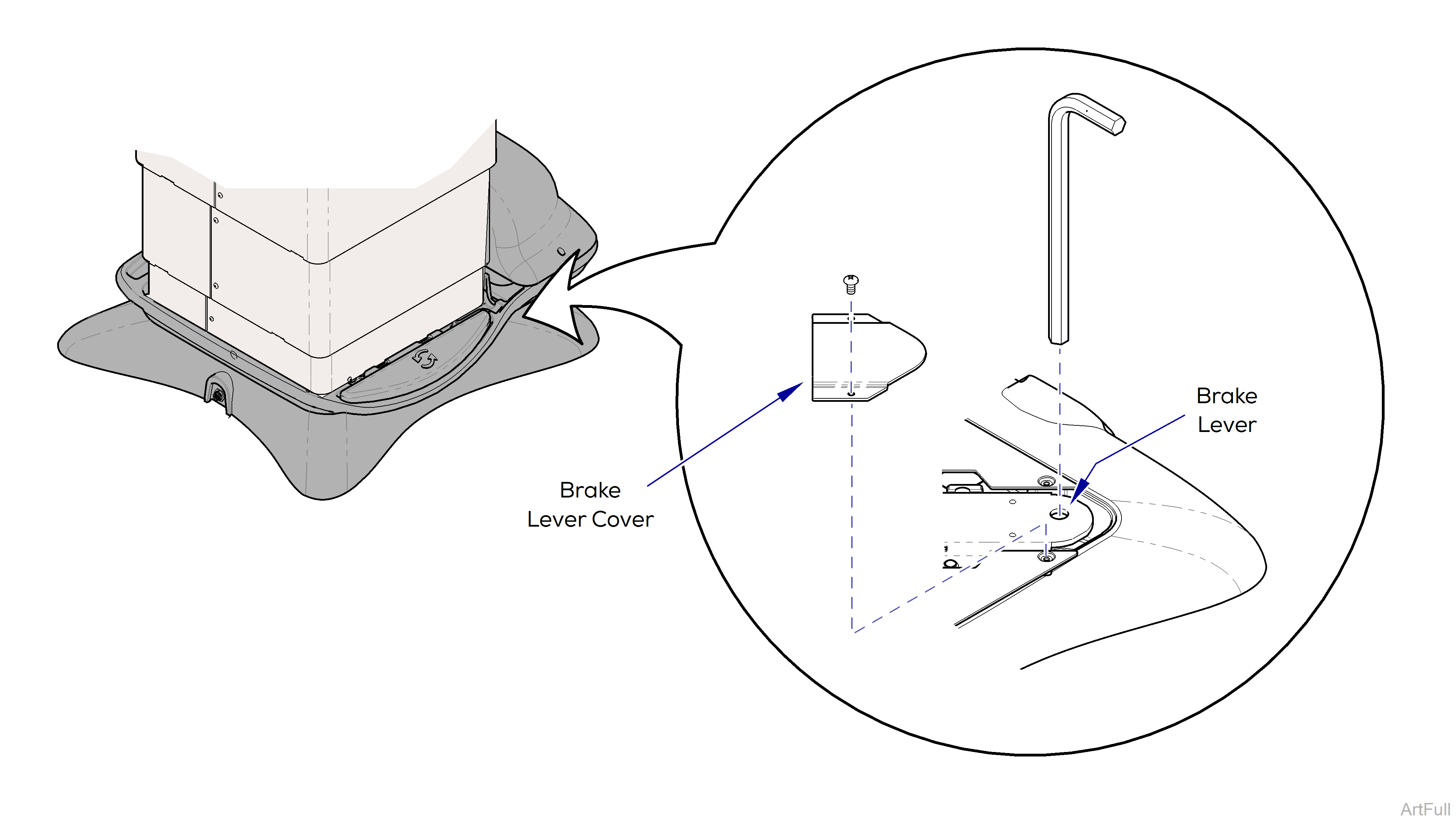
1.Rotate the base to access the brake lever cover.
The brake lever cover is located between the upper and lower base castings at the patient’s left rear corner.
2.Remove brake lever cover.
If the brake will not release, the base can still be rotated manually by applying additional force.
3.Press the brake pedal while watching the brake lever. If the magnet grabs the brake lever, tighten the magnet screw 1/4 turn. If the magnet does not grab the brake lever, loosen the magnet screw 1/4 turn.
4.Check for proper operation. Repeat if necessary.
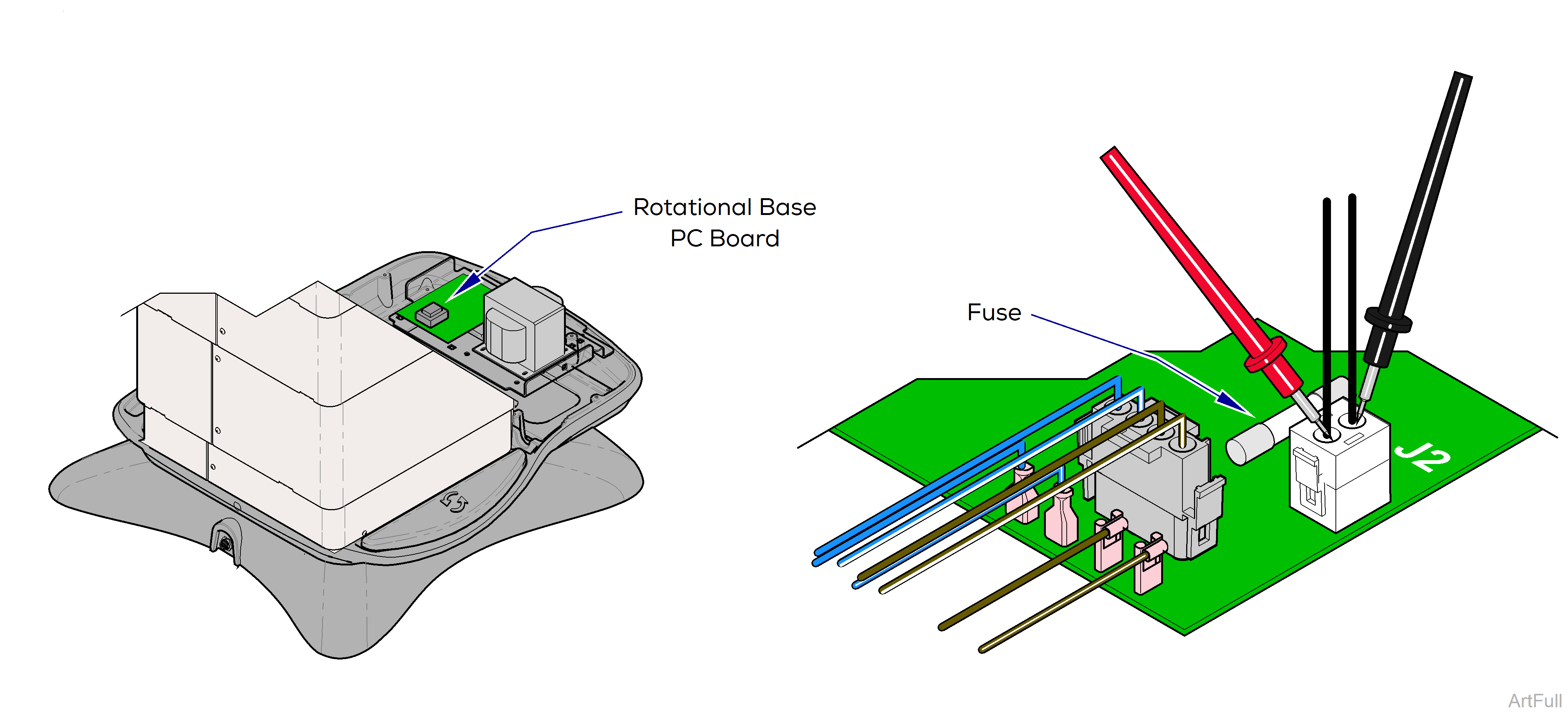
1.Remove PC board cover.
2.Place meter probes on wires at J2 on Rotational Base PC Board.
If no voltage is detected, press and release the brake pedal then check again.
|
Meter Reading |
Required Action |
|---|---|
|
15-21 VAC |
PC board is OK. Perform Electro-magnet Test |
|
0 VAC |
Check Rot. Base PC Board fuse. If fuse is OK, replace the PC board |
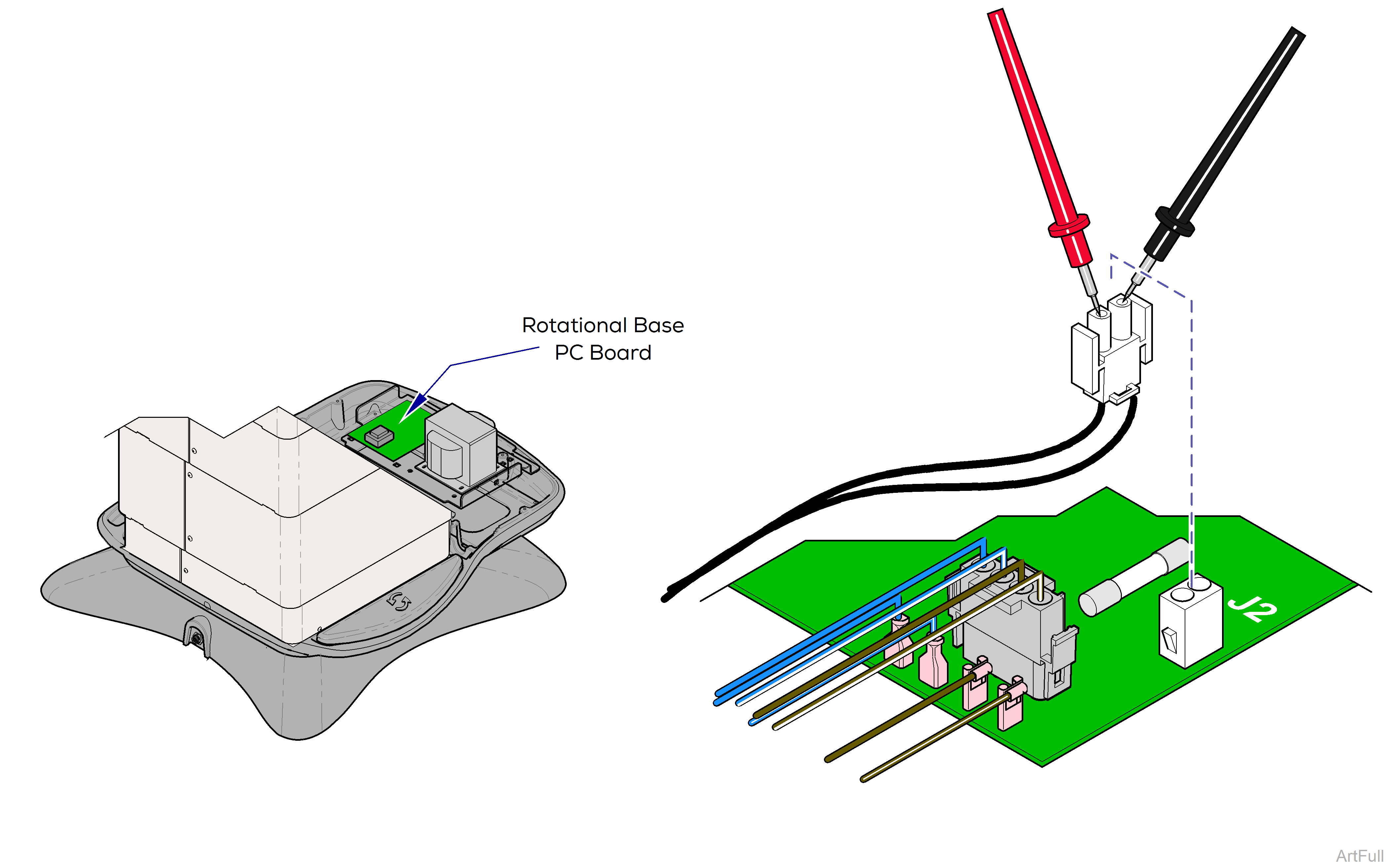
1.Remove PC board cover.
2.Disconnect magnet wire harness from J2 on Rot. Base PC Board.
3.Place meter probes on wire harness.
|
Meter Reading |
Required Action |
|---|---|
|
approximately 10 ohms |
Magnet is OK. Check mechanical components. |
|
OL or less than 5 ohms |
Inspect magnet wire harness. If OK, replace electro-magnet. |
This test allows you to check for line voltage coming thru the EMI filter board without separating the upper and lower castings.
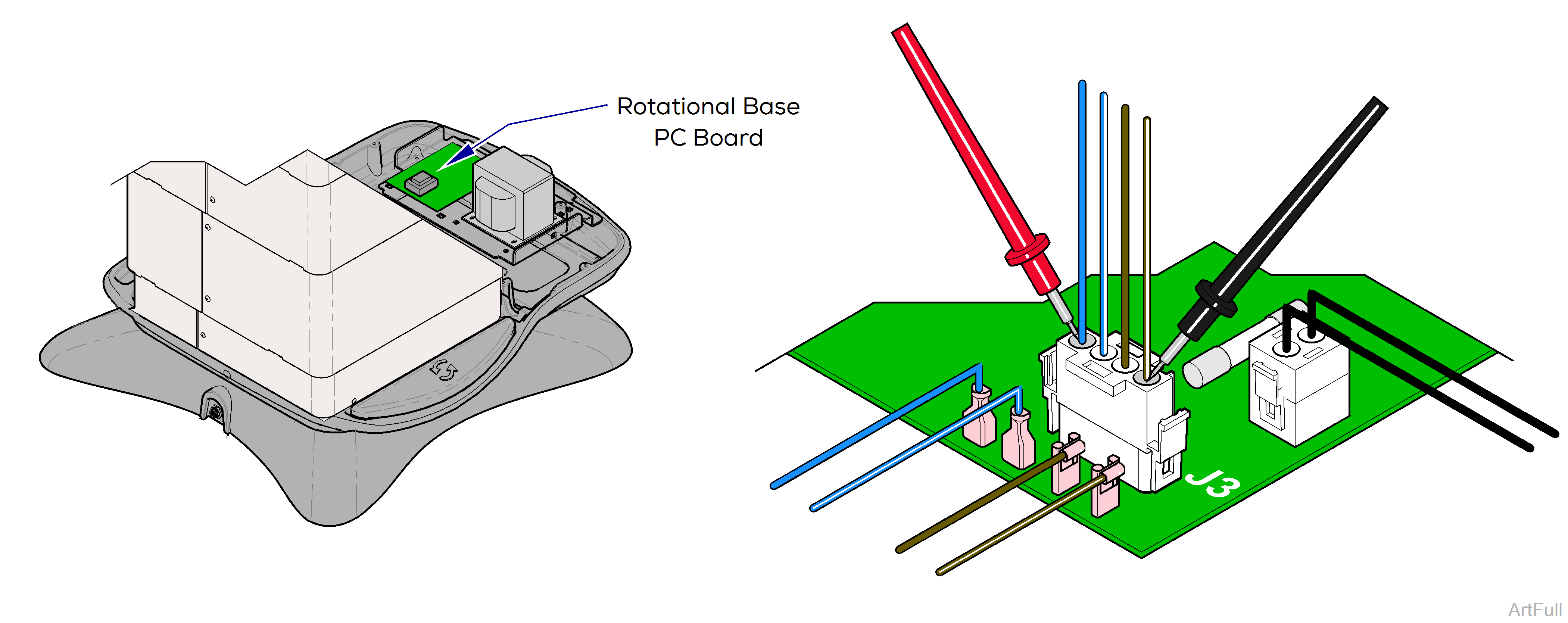
1.Remove PC board cover.
2.Place meter probes on blue wire and brown/white wire at J3 on Rotational Base PC Board
|
Meter Reading |
Required Action |
|---|---|
|
approximately 115 VAC |
EMI filter board is OK. Check connections to main PC board. |
|
0 VAC |
Check primary fuses and wire harness. If fuses are OK, replace EMI filter board. |
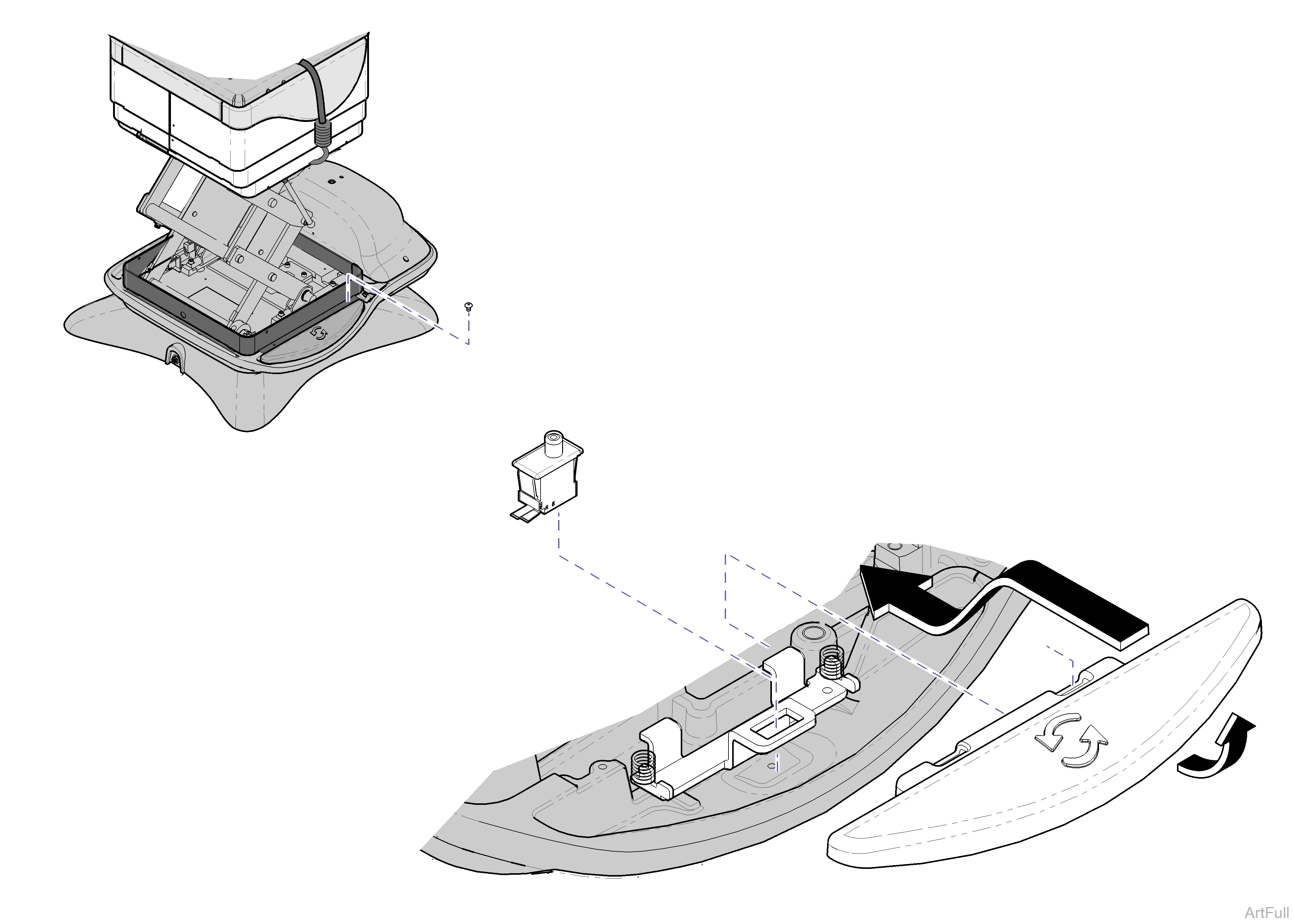
1.Raise base shrouds.
2.Remove two screws from shroud spacer.
3.Remove brake pedal.
Pivot brake pedal toward column, then press down and push forward to release.
Always disconnect chair power cord before removing any covers or shrouds.
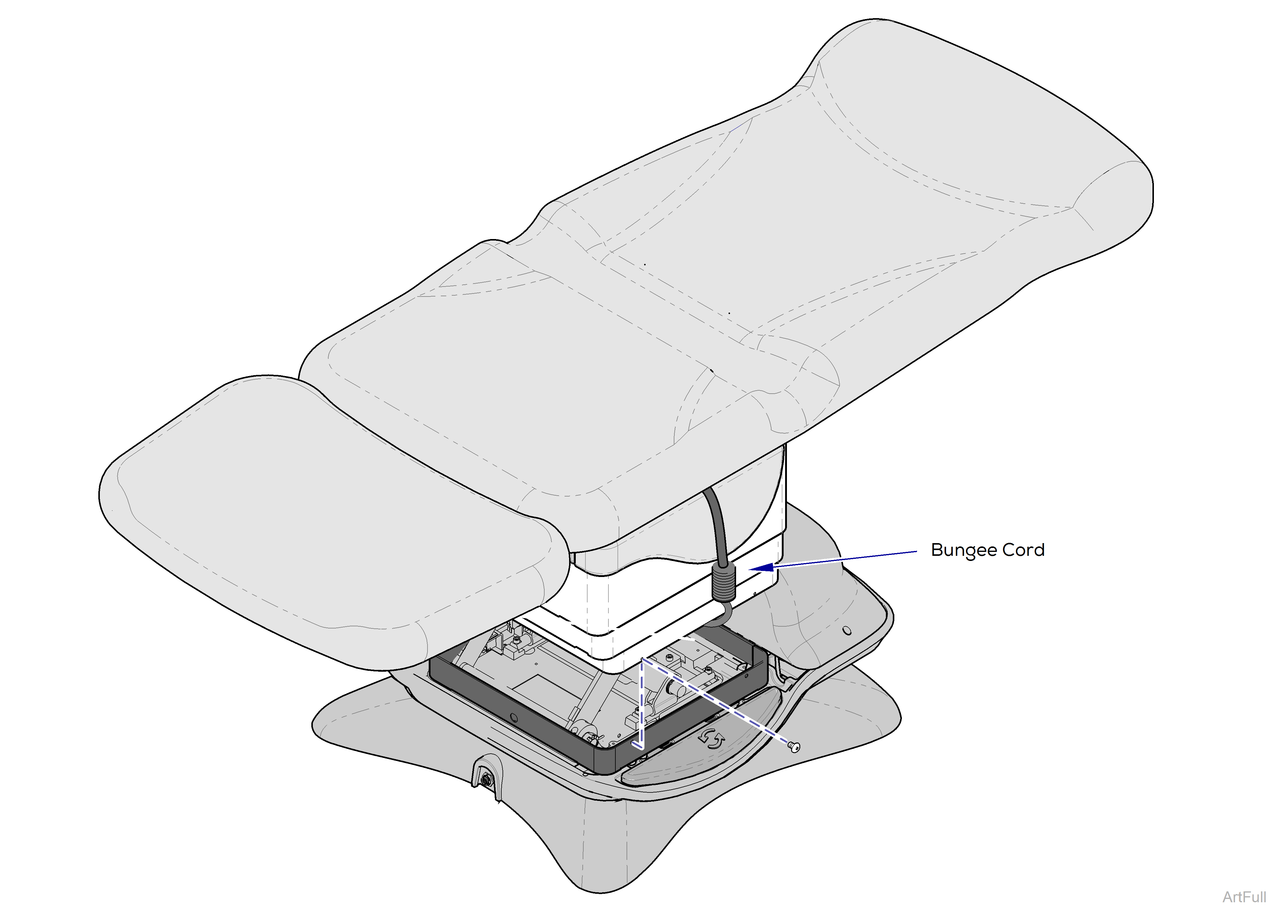
1.Route bungee cord across top of base column, under seat.
It may be necessary to run the Tilt Up function to route bungee cord under seat section.
2.Run Base Up function to its max height. Position chair so that foot and back sections are level as shown.
3.Remove bottom screws from inner shrouds.
4.Raise shrouds, then attach bungee cord hooks under shrouds on both sides.
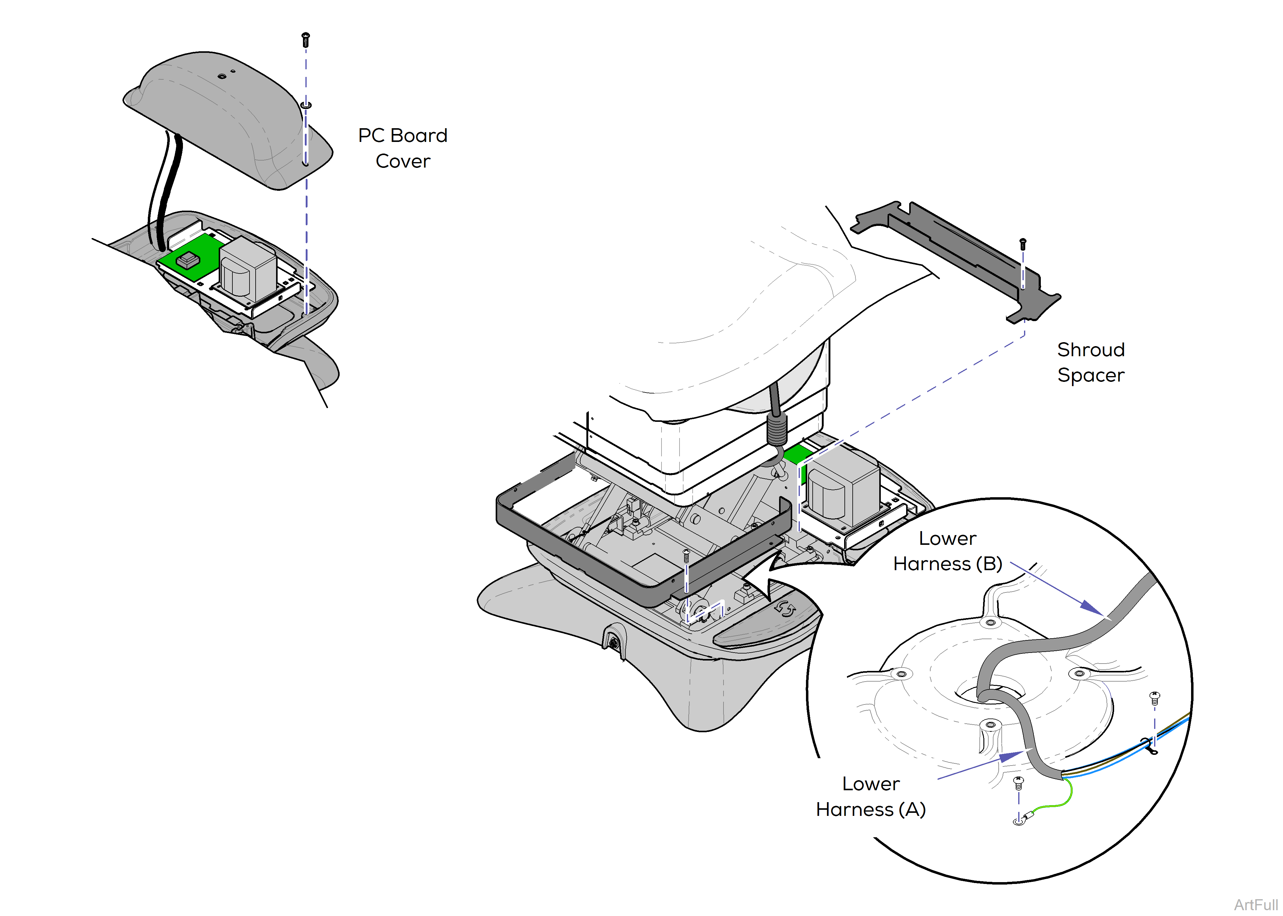
5.Partially separate PC board cover.
Do not disconnect wire harnesses.
6.Remove shroud spacer.
7.Remove wire harness cover.
8.Disconnect ground wire for lower harness (A). Remove cable ties securing lower harnesses (A and B) to base.
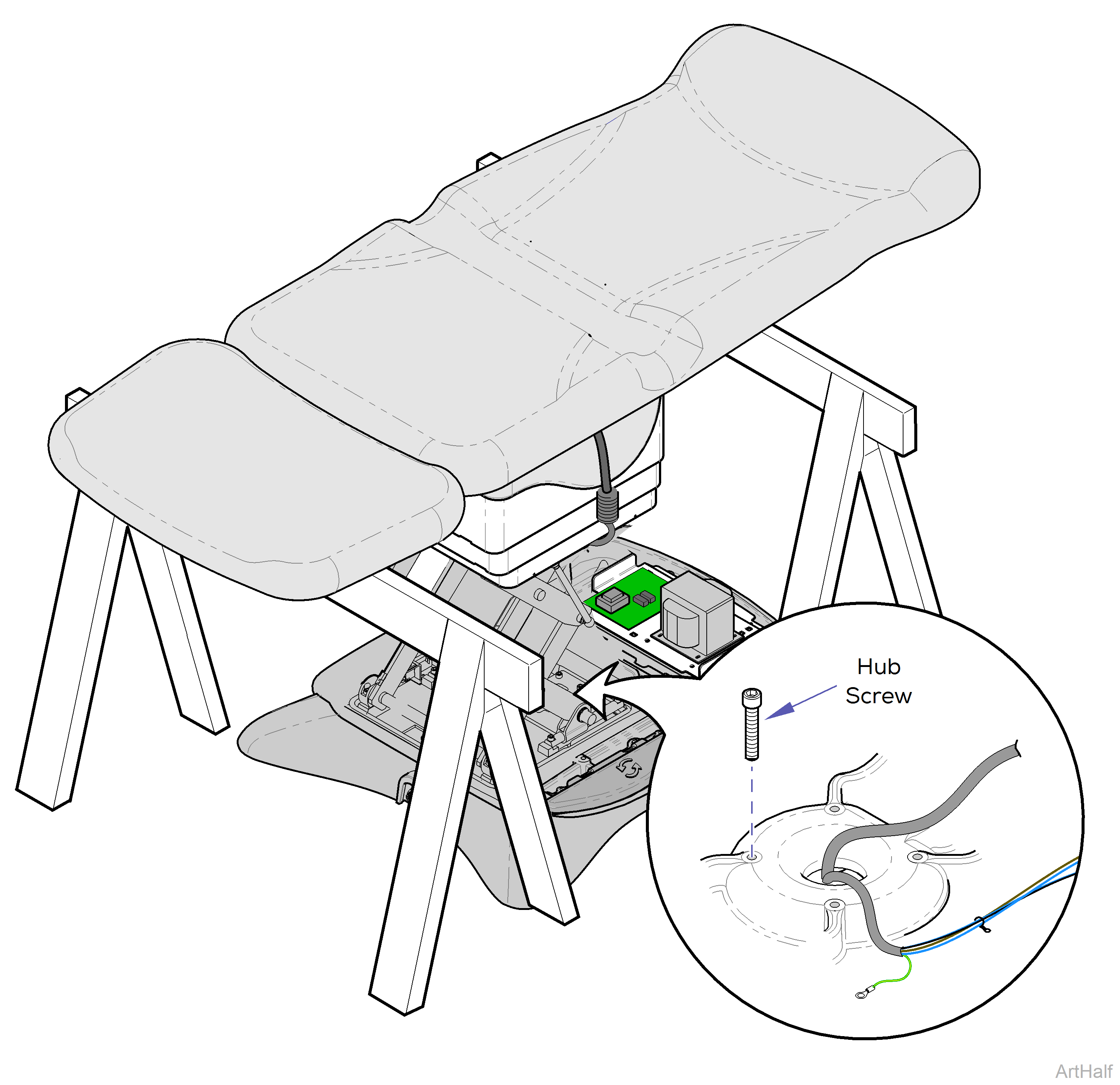
The chair weighs approx 500 lbs (226 kg). Use supports designed for this amount of weight.
9.Position sawhorses, or other suitable supports, under back and foot section weldments.
The chair top / upper base is not secured once the hub screws are removed. Hold onto the chair when performing the following steps.
10.Remove four hub screws.
The steps shown below require power to be connected to the chair. Avoid all contact with wiring and electrical components.
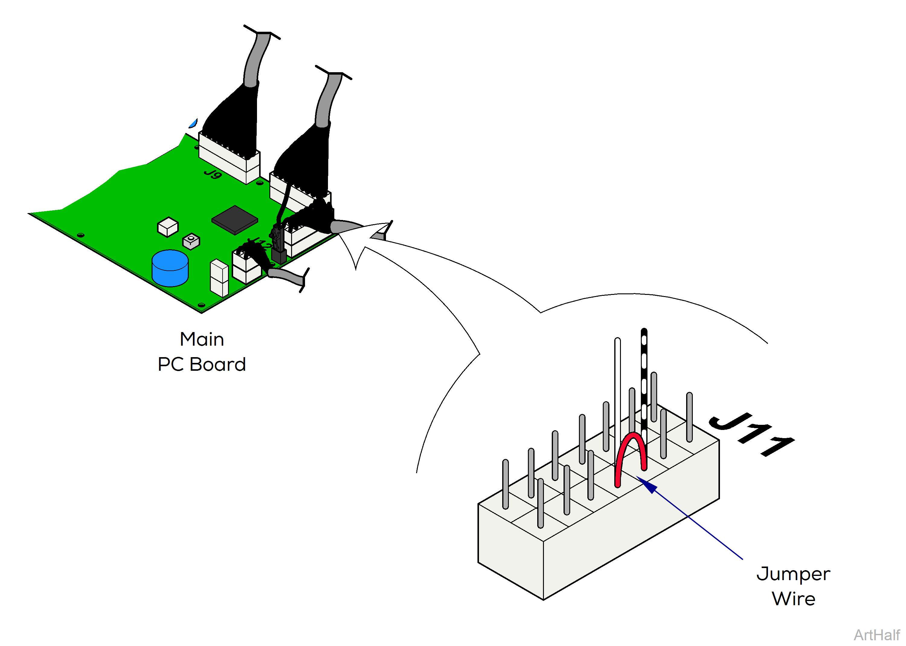
To activate Base Up / Down, it may be necessary to jumper the Foot Extension Crash Limit Switch. Be certain to remove jumper wire when procedure is completed.
The two lower wire harnesses are still connected to upper casting. Running the Base Down function too long may result in damage to the chair.
11.Activate Base Down function until castings separate slightly.
Disconnect chair power cord before performing any of the steps shown here.
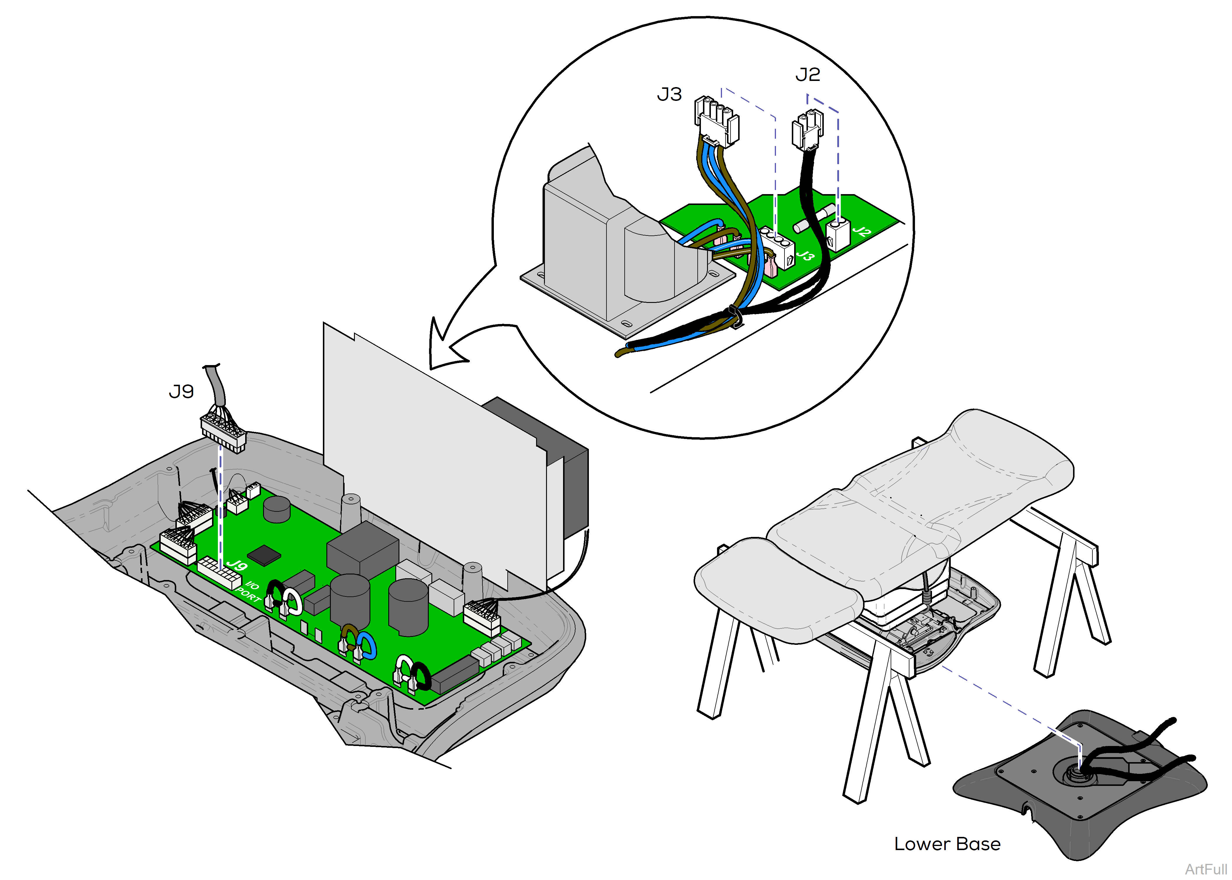
12.Disconnect wire harness from J2 and J3 on rotational base PC board.
13.Disconnect wire harness from J9 on main PC board.
14.Slide lower base assembly out.
Disconnect chair power cord before performing any of the steps shown here.
1.Slide lower base assembly under chair.
To ease installation, align the new lower base assembly in the same position as the old base.
2.Route wire harnesses thru upper casting. Reconnect all wire harnesses as shown.
The chair top / upper base is not secured until the hub screws are installed. Hold onto the chair when performing the following steps.
To activate Base Up / Down, it may be necessary to jumper the Foot Extension Crash Limit Switch. Be certain to remove jumper wire
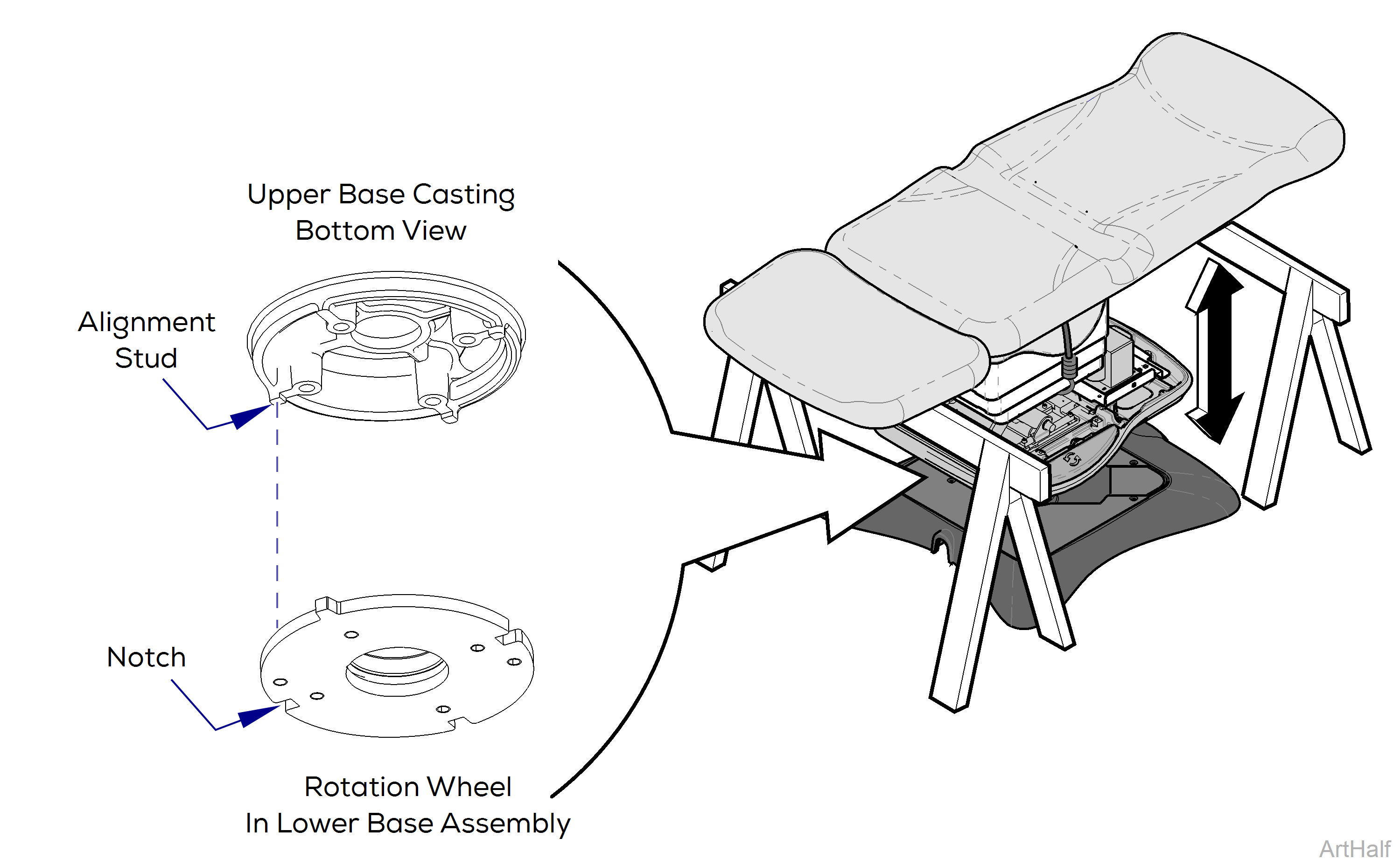
3.Activate Base Up function until chair raises slightly off of supports.
4.Carefully adjust chair top until alignment studs on bottom of upper casting lock into the notches on the rotation wheel.
You will feel chair top drop into place when alignment studs engage notches.
Disconnect the chair power cord before performing the remaining installation steps.
5.Install four hub screws.
6.Replace all cable ties. Connect ground wires for lower harness (A).
7.Install wire harness cover.
8.Install shroud spacer.
9.Replace PC board cover.
10.Remove bungee cord. Secure inner shrouds with screws.
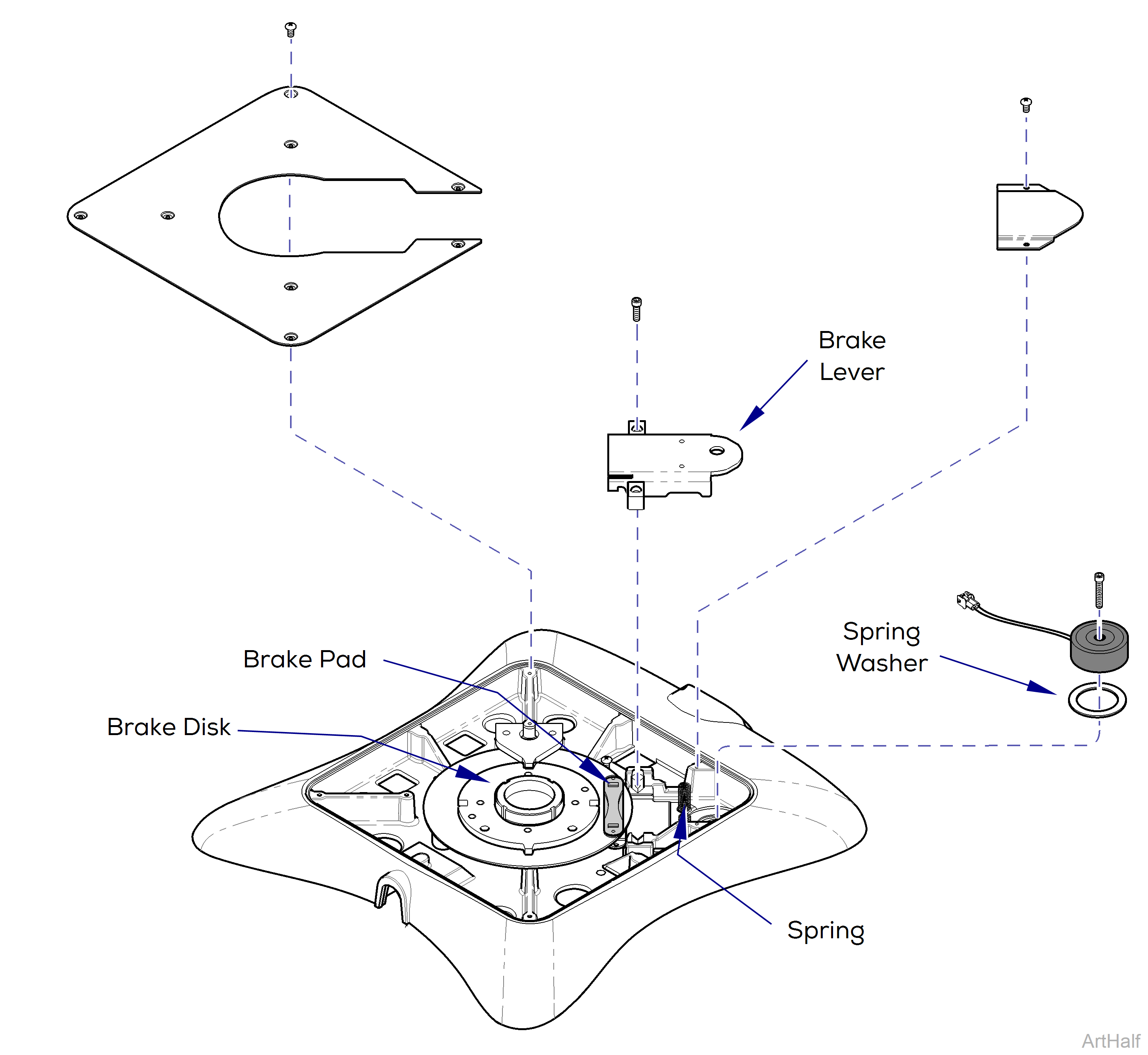
1.Separate upper and lower base castings.
2.Remove corner cover and top cover from lower base assembly.
3.Remove brake lever.
4.Disconnect magnet wire harness. Remove magnet.
To install electro-magnet.
1.Connect magnet wire harness.
2.Install magnet.
Be sure spring washer is in place under magnet.
To install brake lever.
1.Position brake lever so that it aligns with slots in brake pad.
2.Secure lever with two screws.
Be sure roll pins in brake lever align with springs.
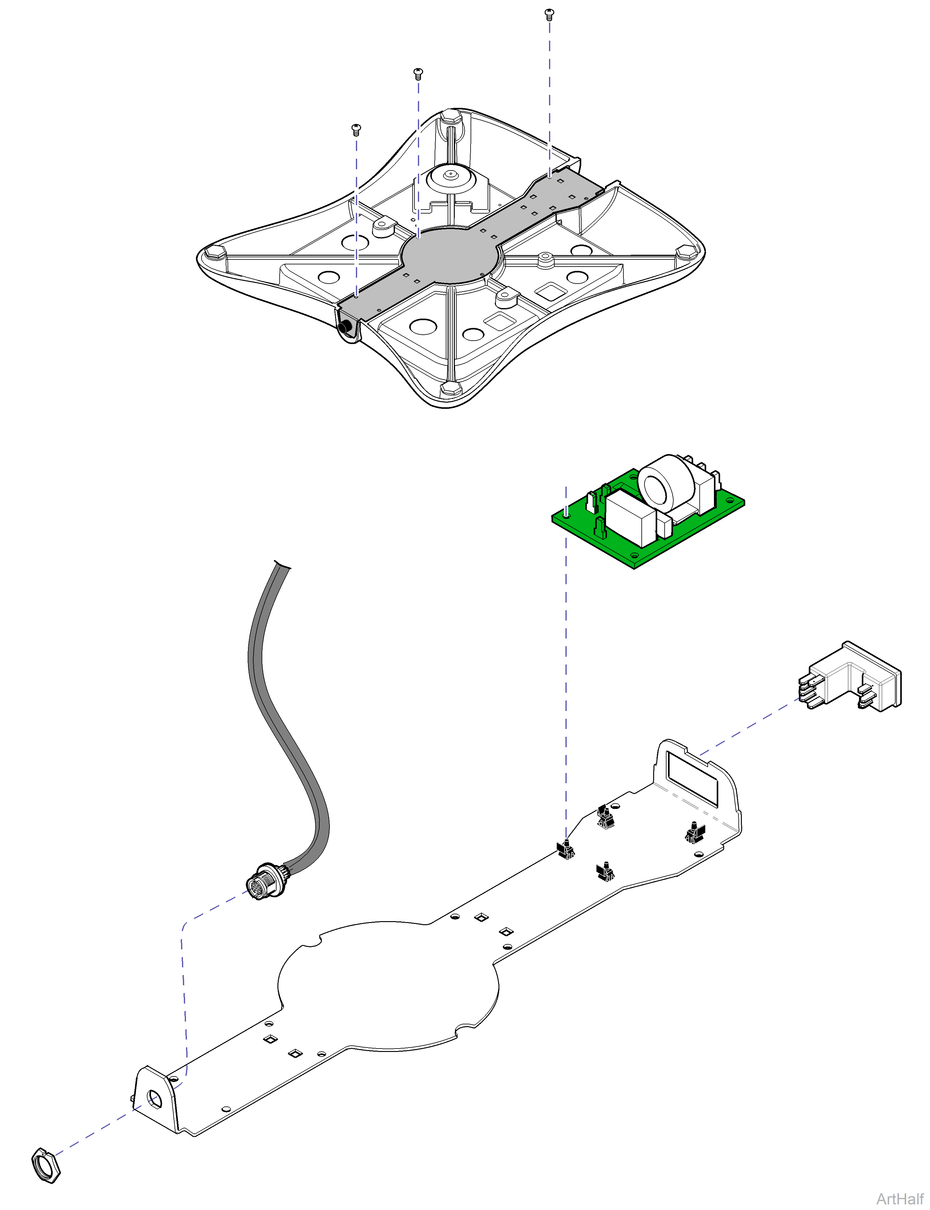
1.Separate upper and lower base castings.
2.Turn lower base assembly upside down. Remove bottom cover.
To remove foot control inlet
1.Unscrew lock nut.
2.Remove foot control inlet / harness assembly.
To remove EMI filter board
1.Tag and disconnect all wires to board.
2.Remove board from mounting studs.
To remove power inlet
1.Tag and disconnect all wires to power inlet.
2.Pry power inlet out of bottom cover.
