647 Chair Tilt Actuator / Limit Switch Test and Repair
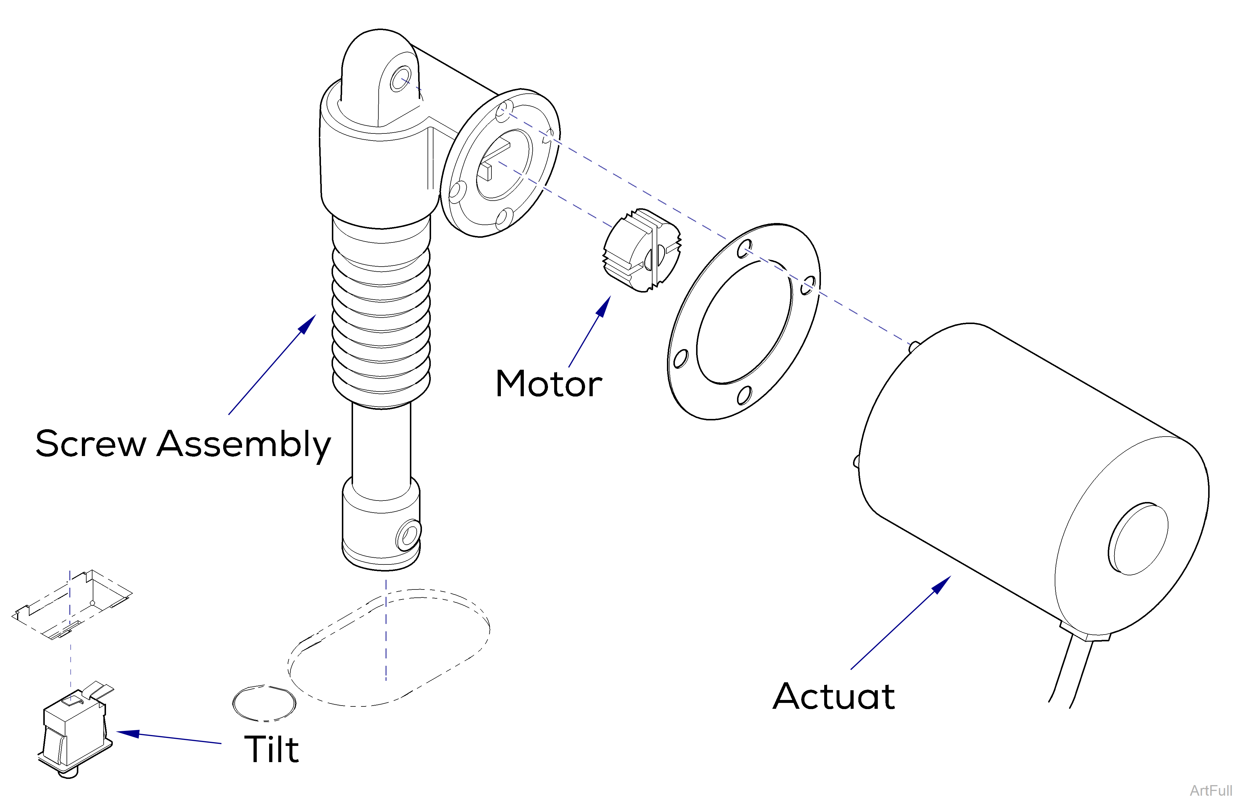
This illustration shows the tilt down limit switch and the three serviceable components of the tilt actuator. Use the table below to isolate the malfunction.
|
Problem |
Required Action |
|---|---|
|
Motor runs, but makes grinding noise. |
Clean / lube actuator threads. Replace actuator if necessary |
|
Motor runs, but chair does not move. |
Inspect / replace motor coupler. |
| Motor does not run. |
Up only - Perform Output Voltage Test at Tilt Sensor |
|
Down only - Perform limit Switch Test. |
|
|
Up and Down - Perform Actuator Motor Test. |
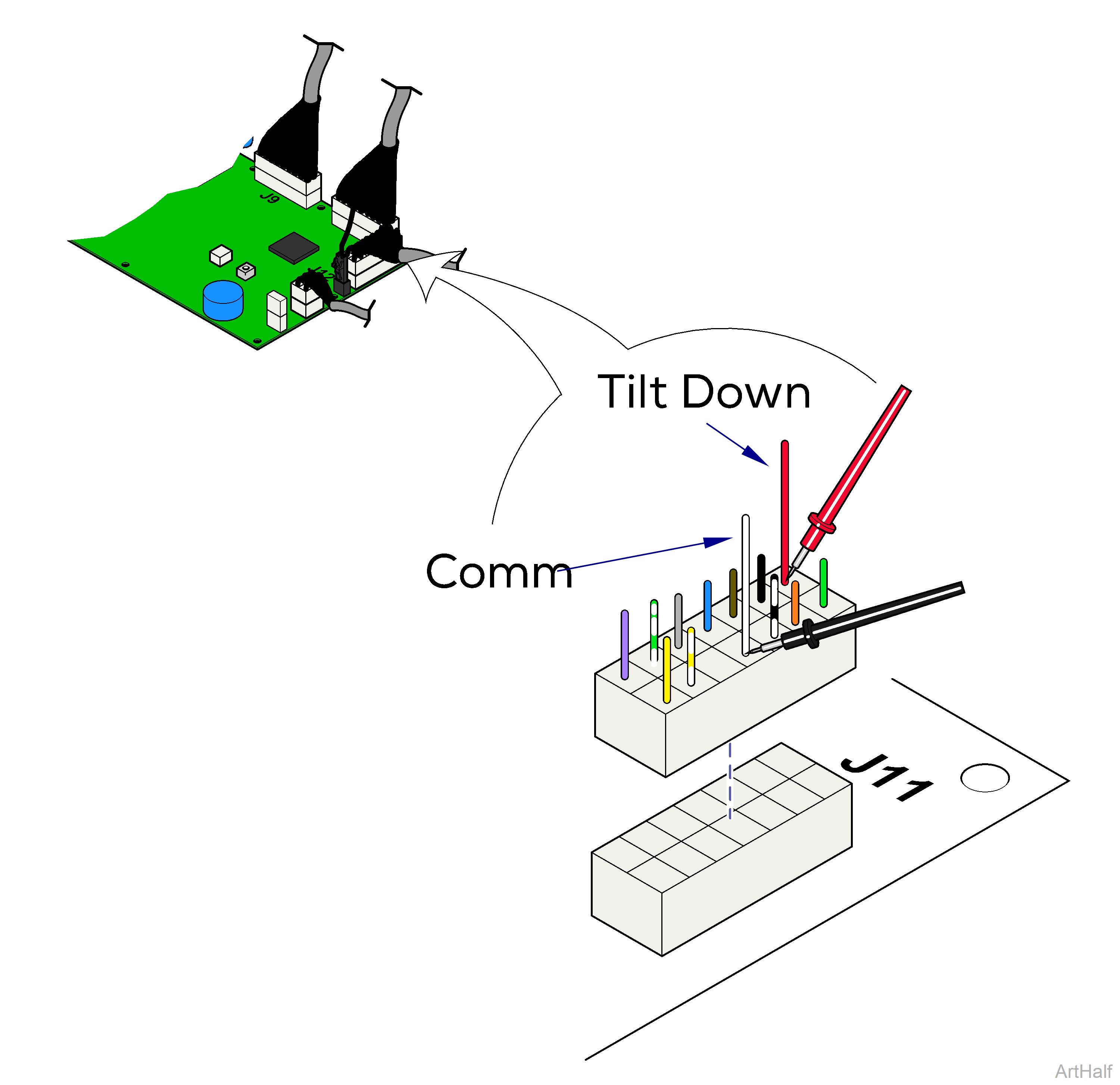
1.Disconnect harness from J11 on main PC board.
2.Place one meter probe on the common, white.
3.Place other probe on the Tilt Down limit switch, red.
Check switch tripped and untripped.
| With Switch Untripped | |
|---|---|
|
Meter Reading |
Required Action |
|
OL |
Perform Limit Switch Harness Test |
| Less than 10 ohms |
Limit Switch / Harness OK, Perform Actuator Motor Test |
| With Switch Tripped | |
|---|---|
|
Meter Reading |
Required Action |
|
OL |
Limit Switch / Harness OK Perform Actuator Motor Test |
| Less than 10 ohms |
Perform Limit Switch Harness Test |
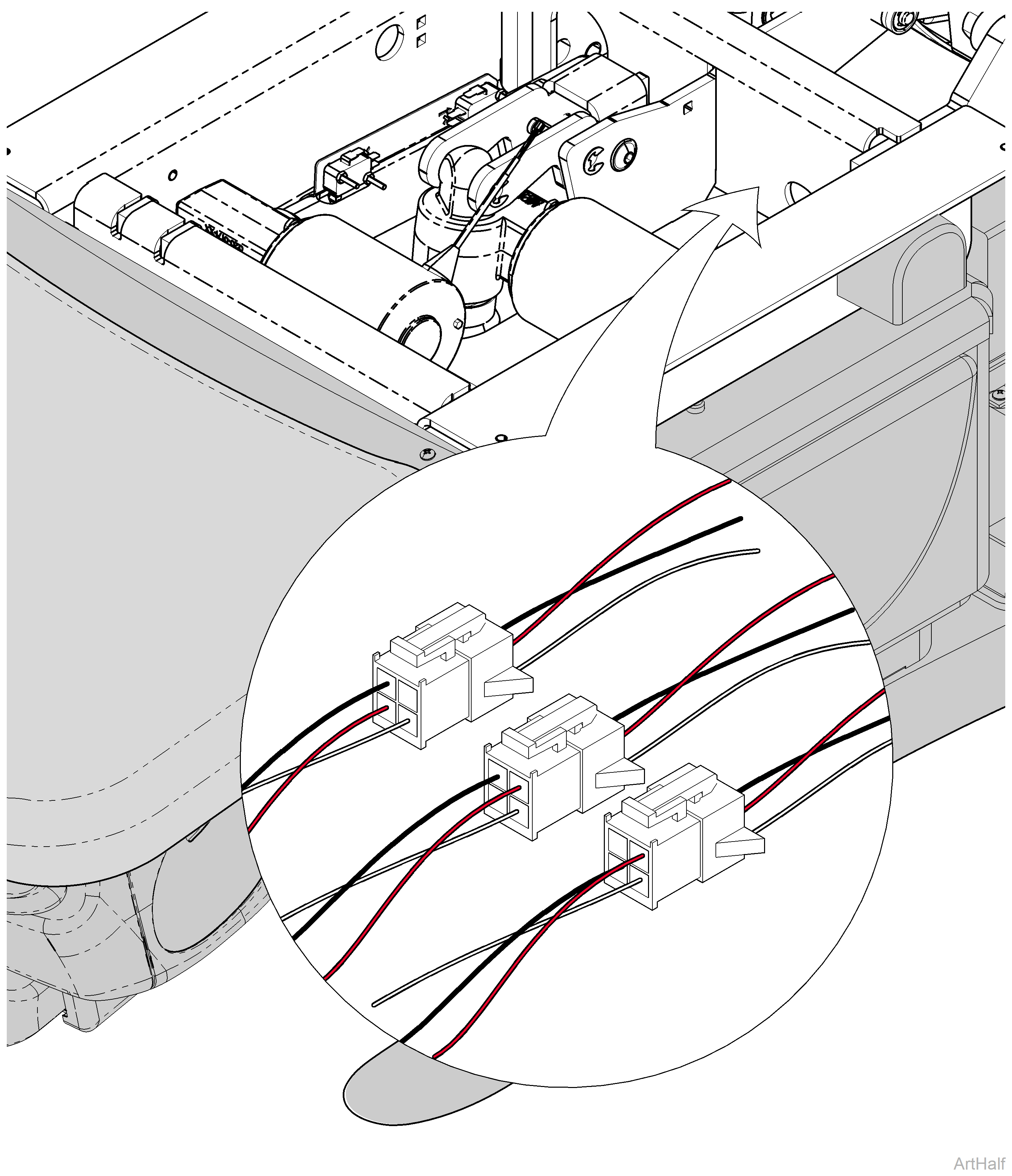
1.Unplug the appropriate limit switch harness.
2.Measure continuity.
|
When |
Meter reading should be |
|---|---|
| Actuator Full Up |
White to Black - Open |
|
White to Red - Closed |
|
| Actuator Full Down |
White to Black - Closed |
|
White to Red - Open |
|
| Actuator Midway Point |
White to Black - Closed |
|
White to Red - Closed |
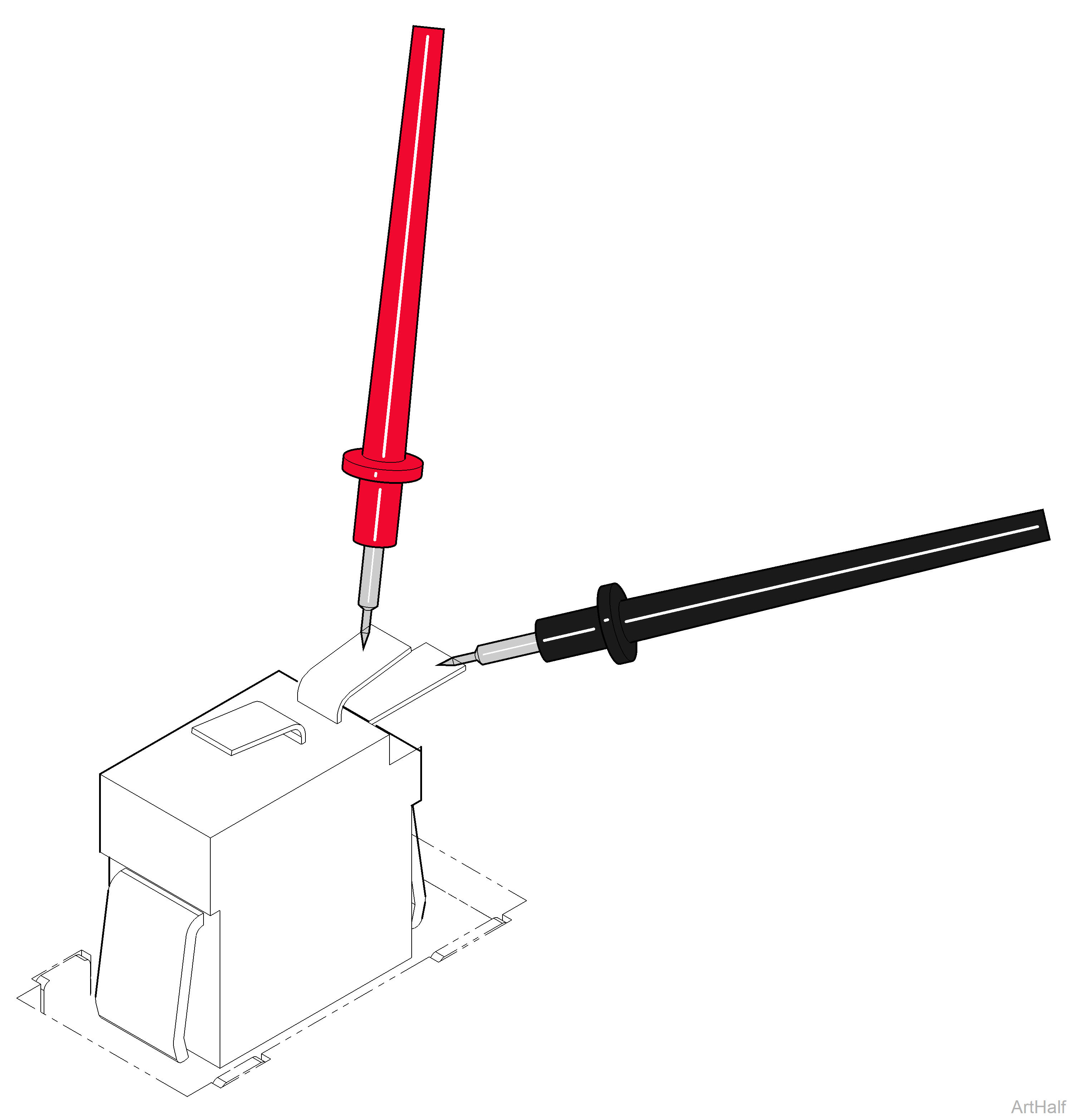
1.Disconnect wires from switch.
2.Place meter probes on COM and NC terminals.
Check switch tripped and untripped.
| With Switch Untripped | |
|---|---|
|
Meter Reading |
Required Action |
|
OL |
Replace Limit Switch |
|
Less than 5 ohms |
Limit Switch OK. Replace Limit Switch Harness |
| With Switch Tripped | |
|---|---|
|
Meter Reading |
Required Action |
|
OL |
Limit Switch OK. Replace Limit Switch Harness |
|
Less than 5 ohms |
Replace Limit Switch |
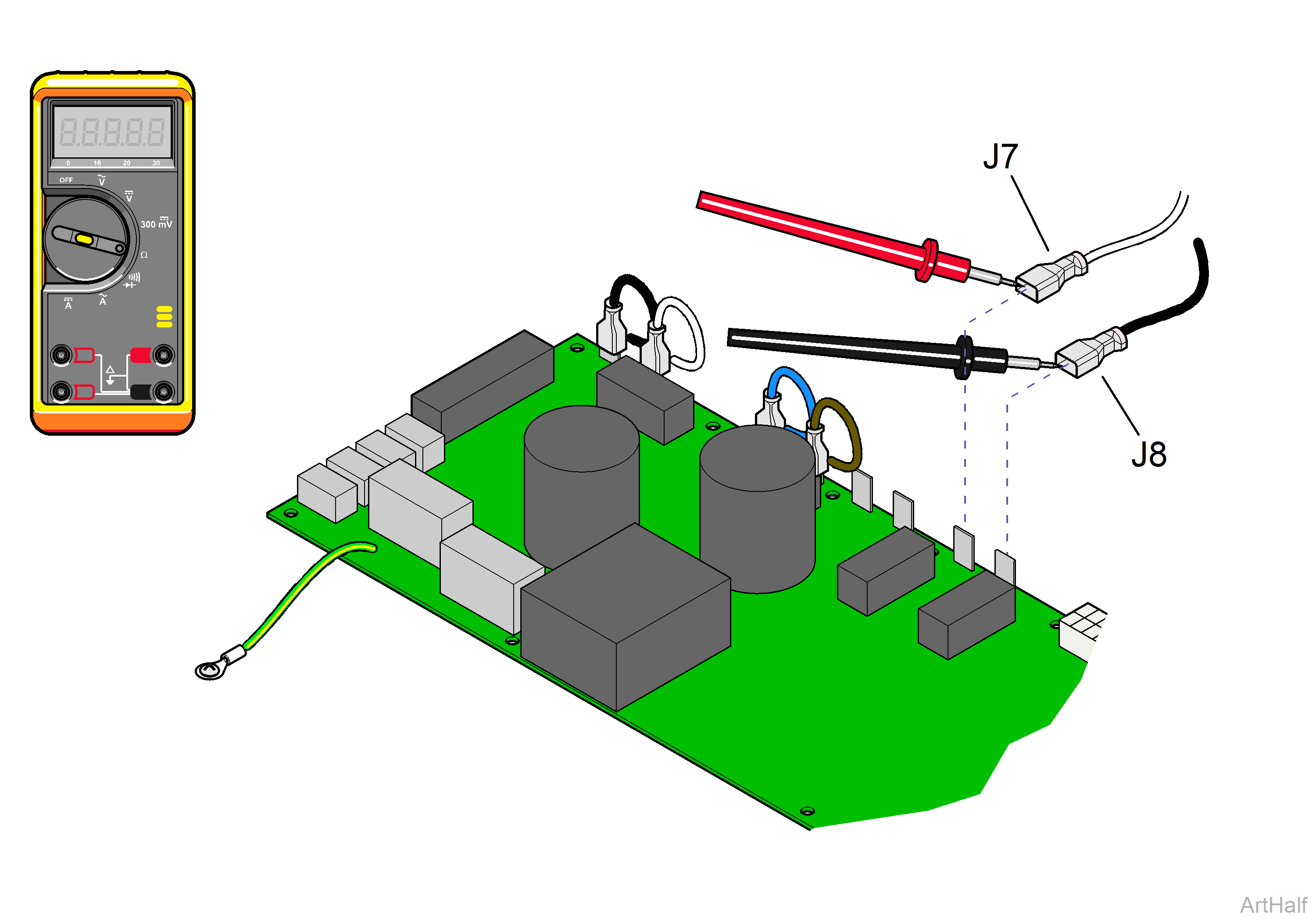
1.Tag and disconnect tilt actuator wires, J7 and J8.
2.Place meter probes on actuator wires.
3.Check meter reading.
|
Meter Reading |
Required Action |
|---|---|
|
1 to 10 ohms |
Actuator motor OK. Perform Motor Ground Test |
|
OL or less than 1 ohm |
Replace actuator motor |
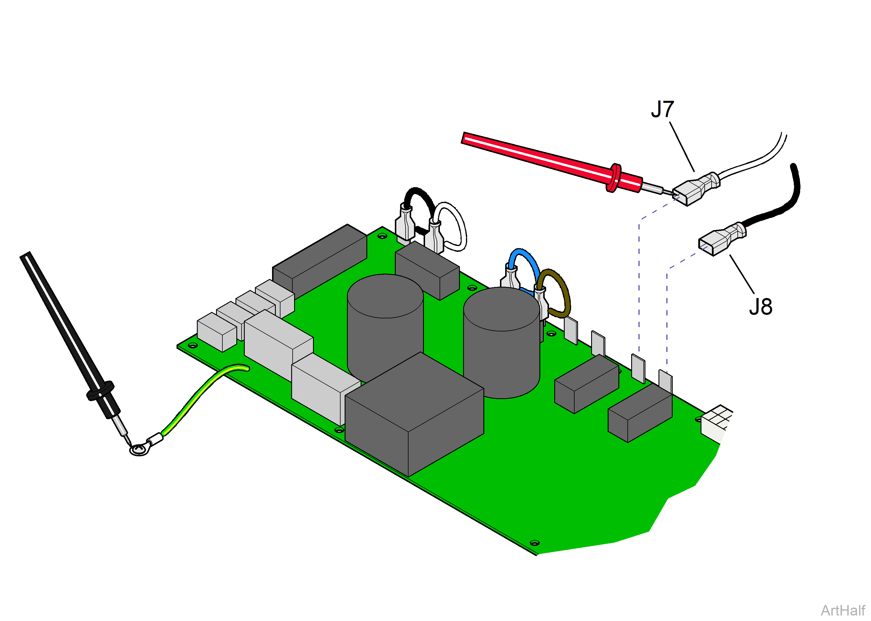
1.Place one meter probe on actuator wire J7. Place other probe on PC board ground wire.
2.Check meter reading.
3.Repeat for J8.
|
Meter Reading |
Required Action |
|---|---|
|
OL or more than 1 mega-ohm |
Motor Harness OK. Perform PC Board Test |
|
Less than 1 ohm |
Replace actuator motor |
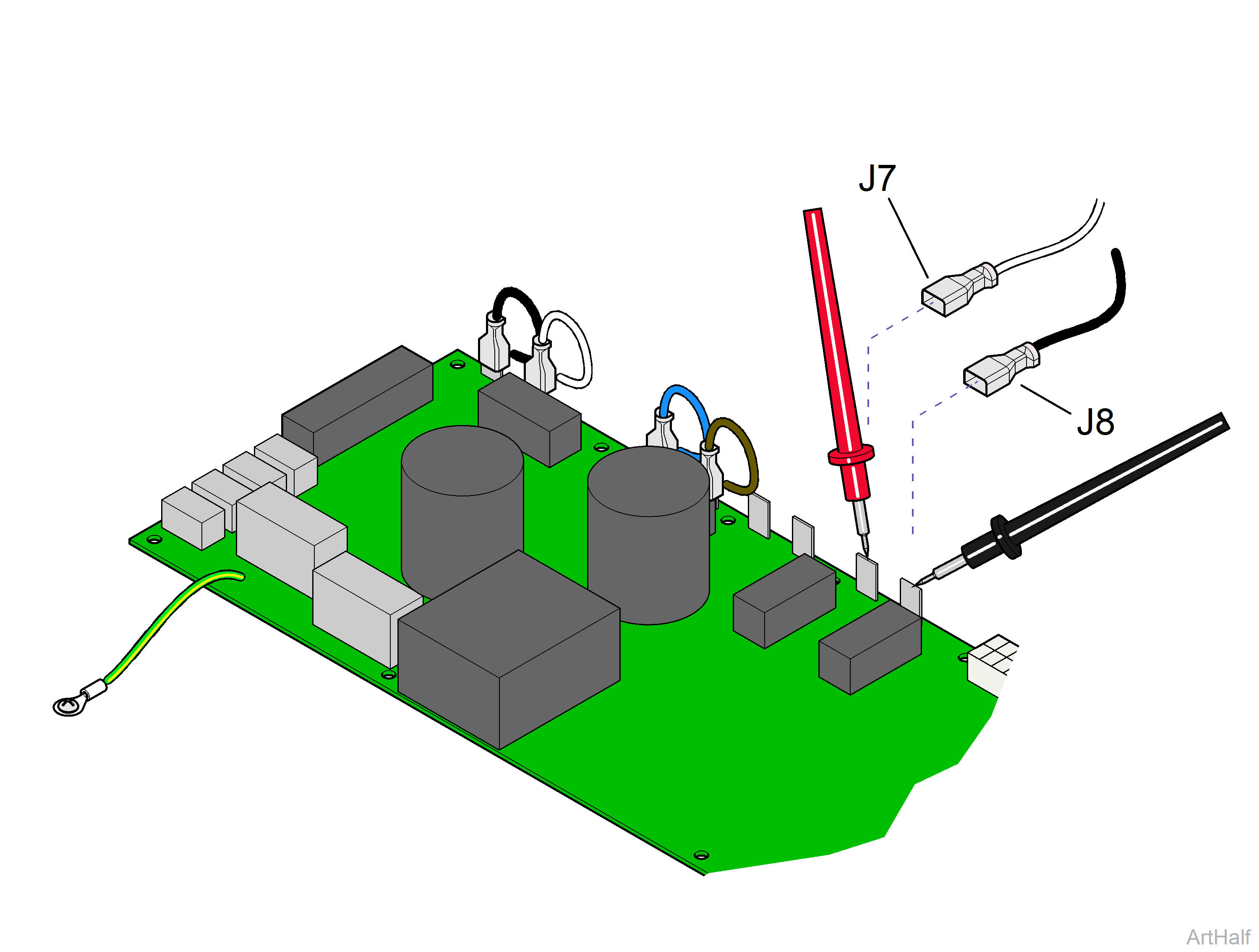
1.Tag, then disconnect tilt actuator wires from J7 and J8.
2.Place meter probes on J7 and J8 terminals on PC board. Set Meter to VDC setting.
3.Activate the Tilt Up function. Check meter reading.
4.Repeat for Tilt Down function.
|
Meter Reading |
Required Action |
|---|---|
|
Approx 48 VDC |
PC board OK |
|
Out of range |
Replace PC board |
