230 Universal Procedures ChairBack Actuator Test and Repair
The Back Actuator has no serviceable components. If the actuator malfunctions, it must be replaced.
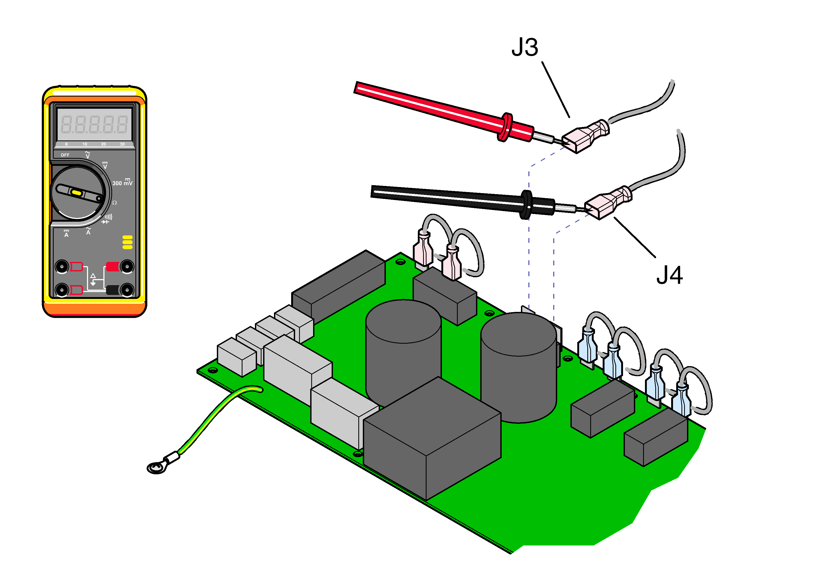
1.Tag / disconnect back actuator wires J3 and J4.
2.Place meter probes on actuator wires. Check meter reading.
|
Meter Reading |
Status |
Required Action |
|---|---|---|
|
1 to 10 Ω |
|
Actuator motor OK, Perform Motor Ground Test |
|
OL or less than 1 Ω |
|
Replace motor |


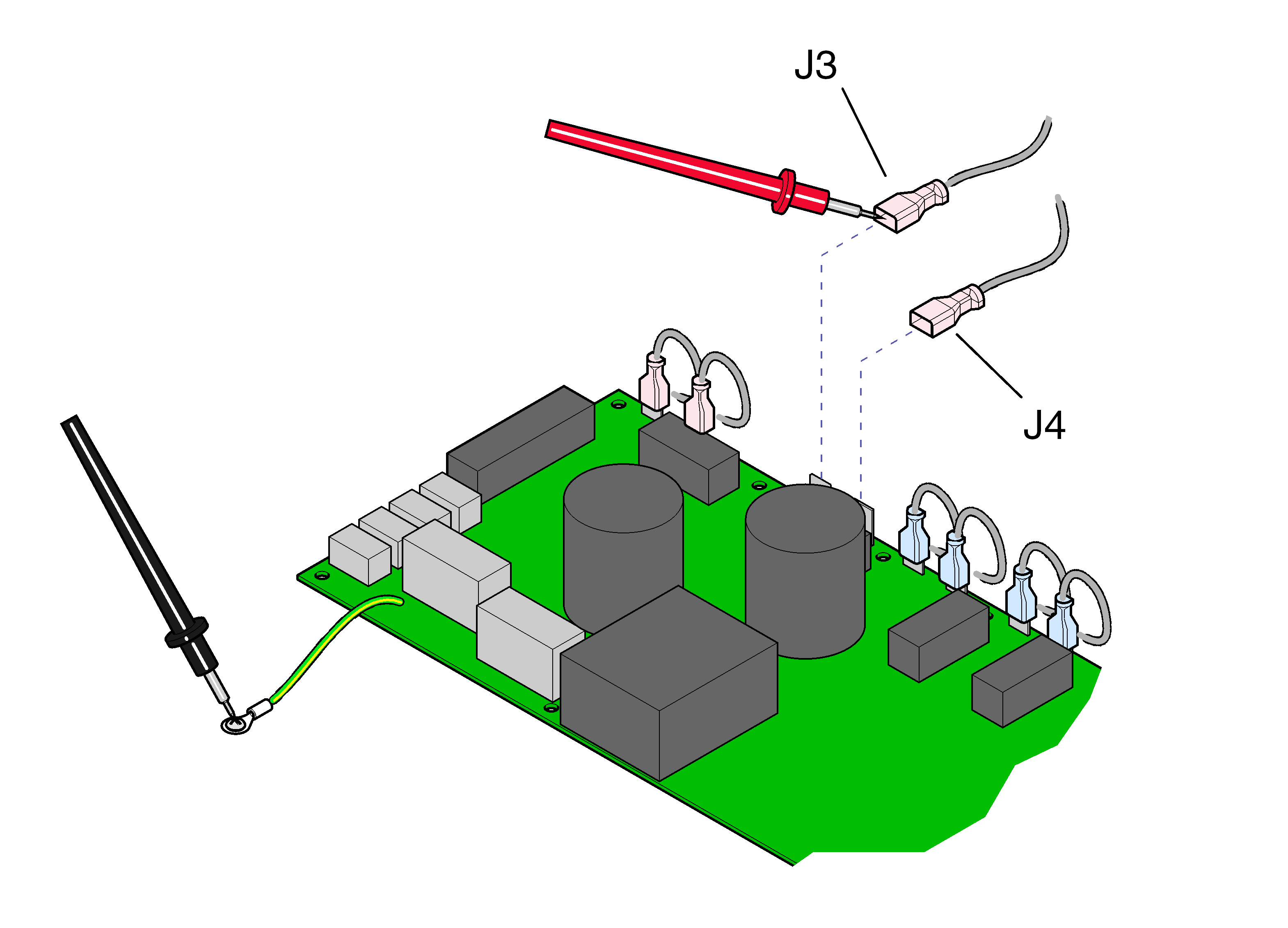
1.Place one meter probe on actuator wire J3. Place other meter probe on PC board ground wire. Check meter reading. Repeat for J4.
|
Meter Reading |
Status |
Required Action |
|---|---|---|
|
OL or less than 1 M Ω |
|
Motor harness OK, Perform PC Board Test |
|
Less than 1 Ω |
|
Replace motor |
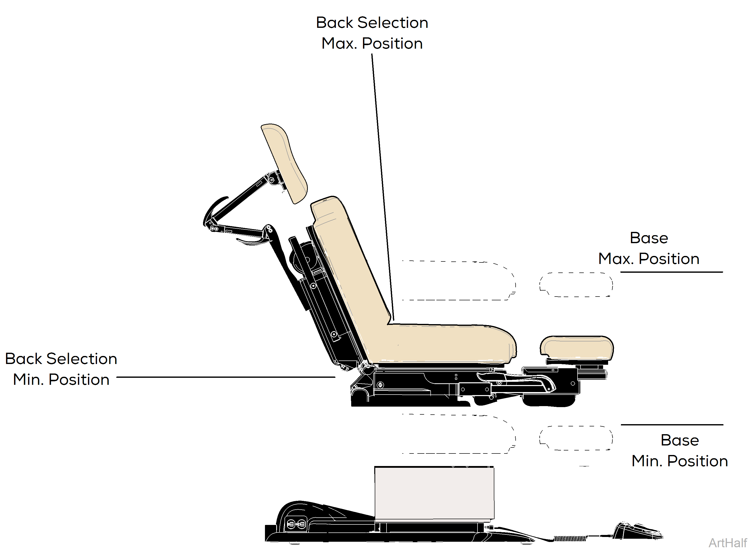
1.This test cannot be performed with the back section in the max. or min. position. If necessary, reposition the back section. Refer to: Base PC Board Test
2.Move the base function so that it is approximately halfway between the maximum and minimum positions.
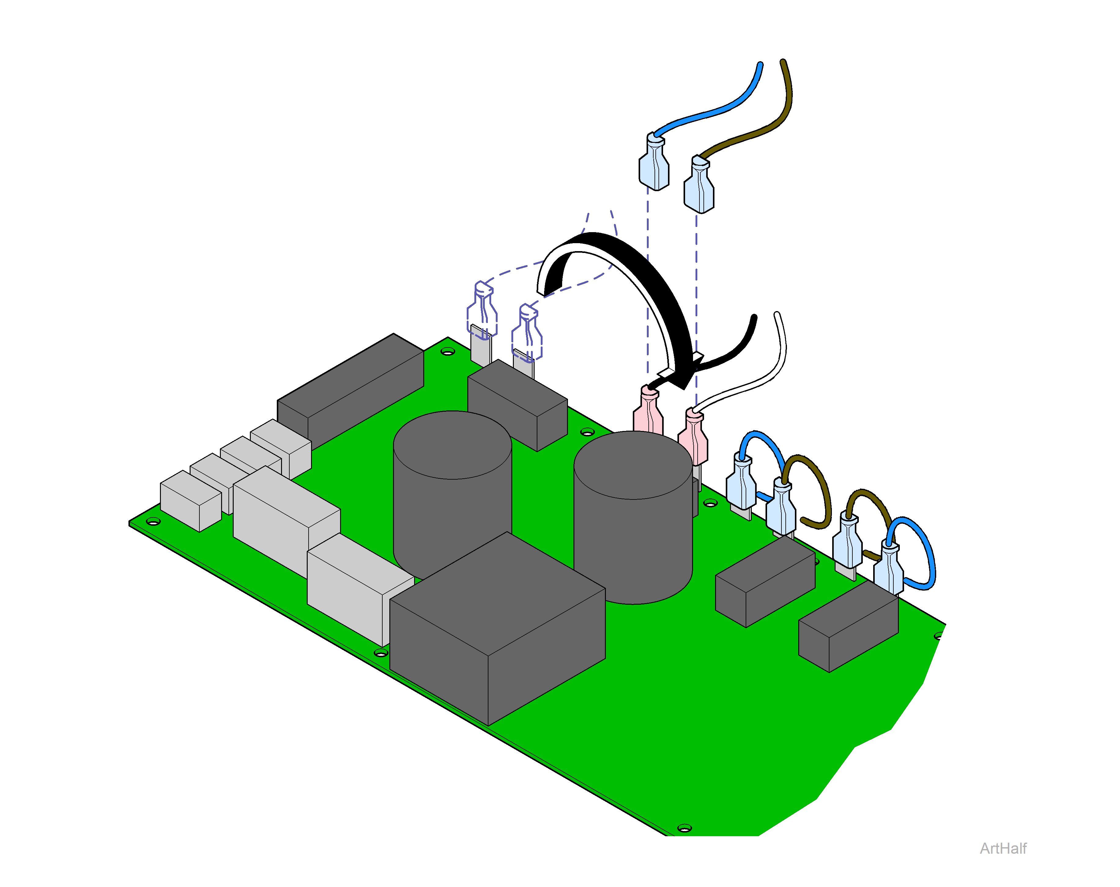
3.Disconnect back actuator wires from J3 and J4.
4.Move black wire from J1 to J3. Move white wire from J2 to J4.
The base limit switches will not stop movement during this test. Do not run past max. / min. positions.
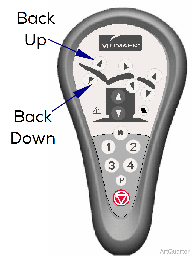
5.Press and hold Back Up button for 5 seconds. Does the base move up, then stop and beep? If Yes, go to Step 6. If No, replace PC Board.
6.Press and hold Back Down button for 5 seconds. Does the base move down, then stop and beep? If Yes, PC Board is OK. If No, replace PC Board.
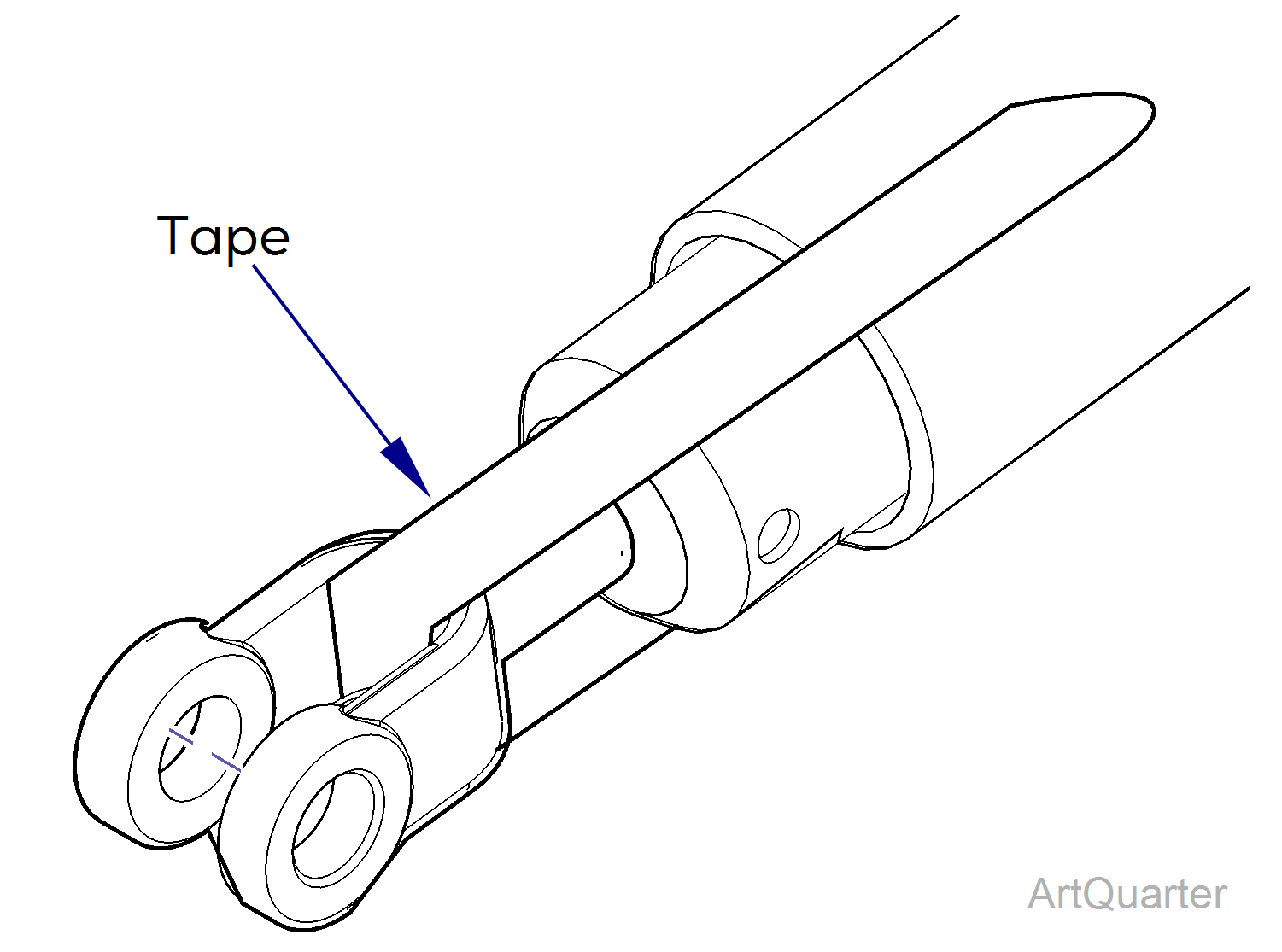
Do not remove tape from new actuator, until instructed to do so. Doing so will allow the actuator shaft and yoke to rotate resulting in misalignment of the internal limit switches.
Remove and replace cable ties and wire clamps as necessary.
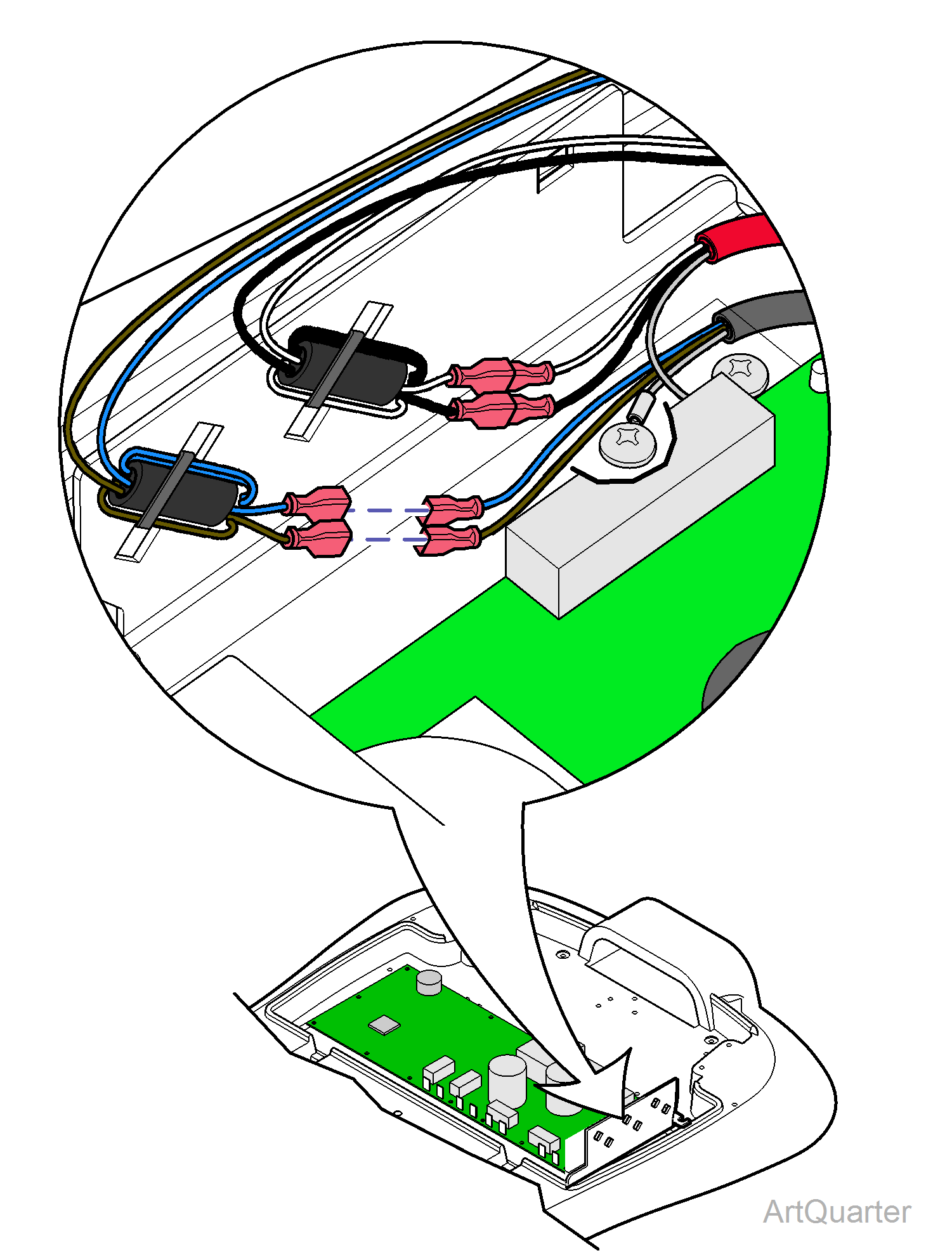
1.Disconnect back actuator wires from choke harness. Disconnect ground wire. Pull actuator wire up thru chair.
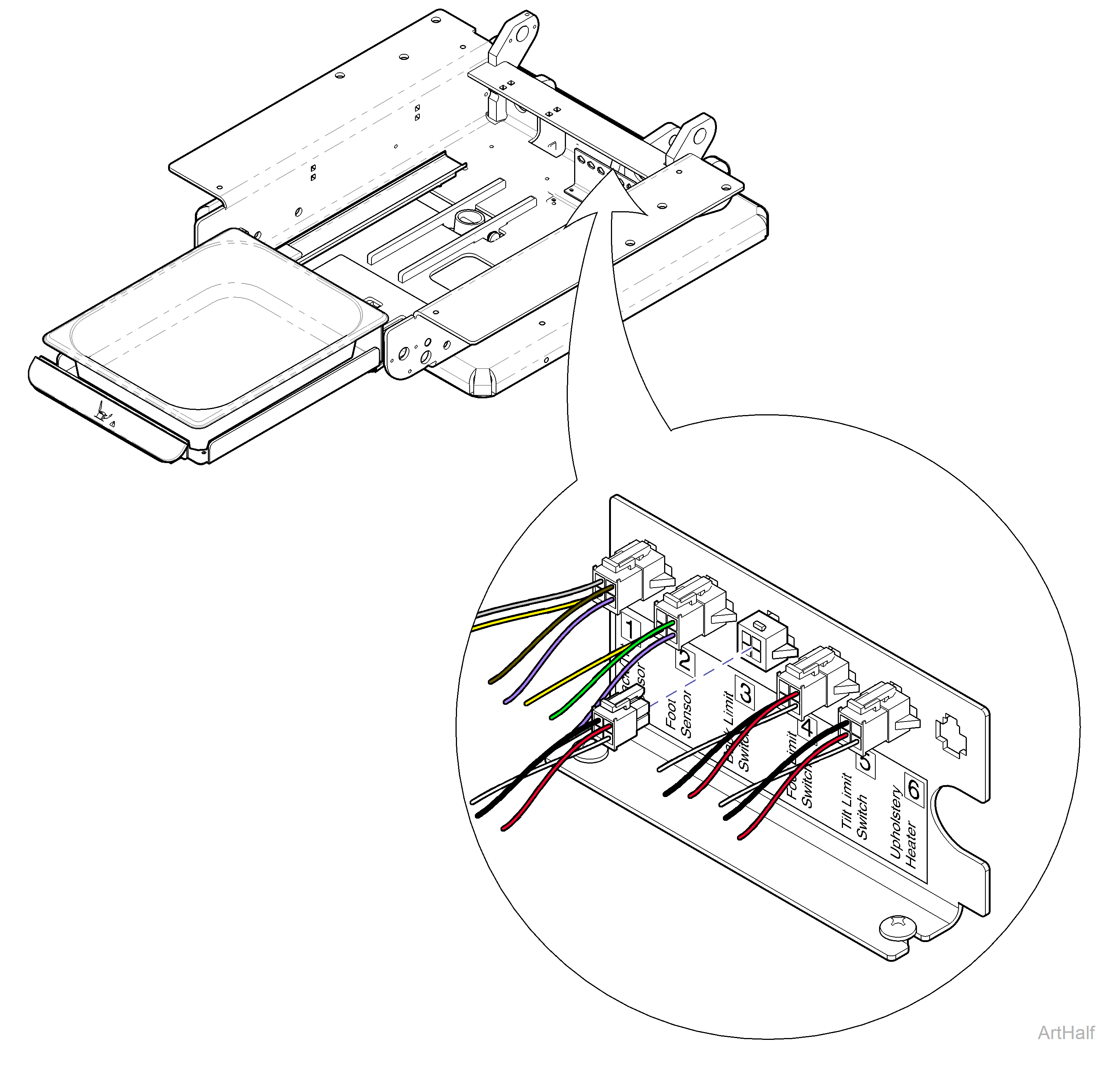
2.Disconnect back limit switch harness [3] from junction board.
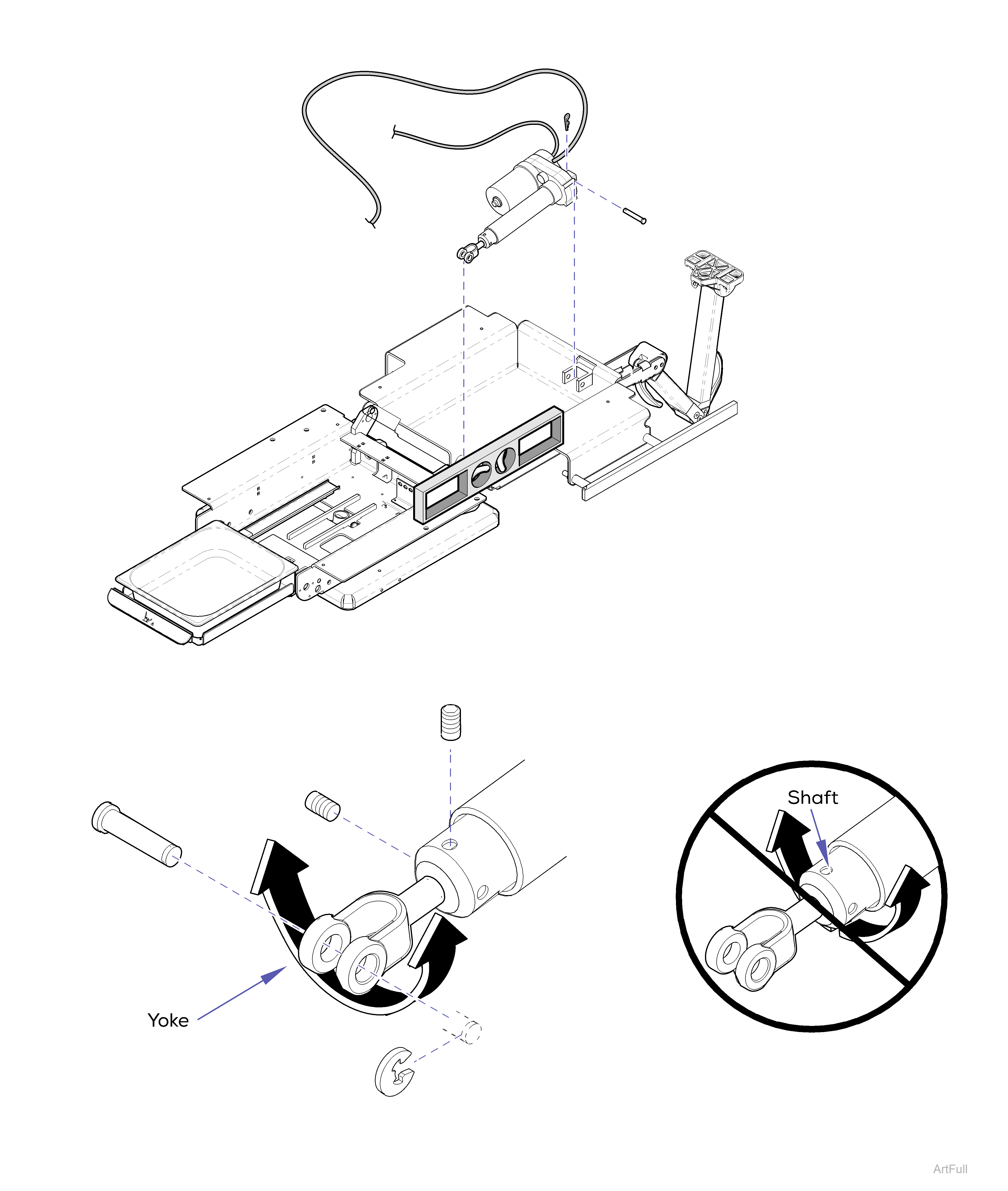
3.Remove yoke clevis pin.
4.Remove base clevis pin and actuator.
1.Install actuator, base clevis pin and cotter pin.
Carefully remove tape from actuator yoke. Do not rotate the actuator shaft! Rotate yoke only enough to align holes.
2.Level back and seat weldments. Rotate yoke to align holes. Install yoke clevis pin and clip ring. Install two set screws.
3.Route back limit switch harness and connect to junction board.
4.Route actuator wire down thru chair. Connect actuator wires to choke harness (brown to brown and blue to blue). Connect ground wire.
