230 Universal Procedures Chair Base Actuator Test and Repair
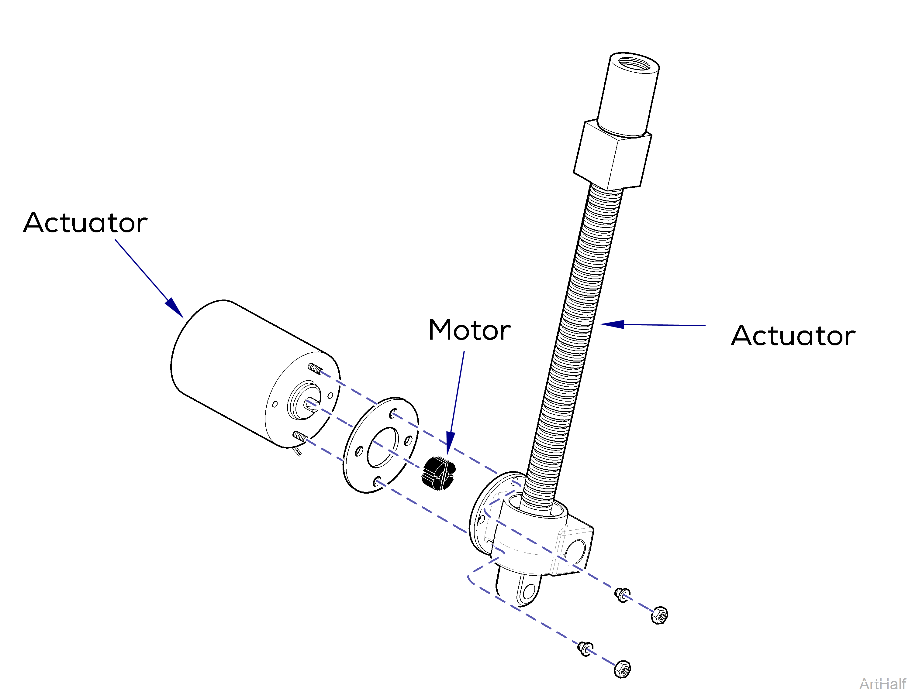
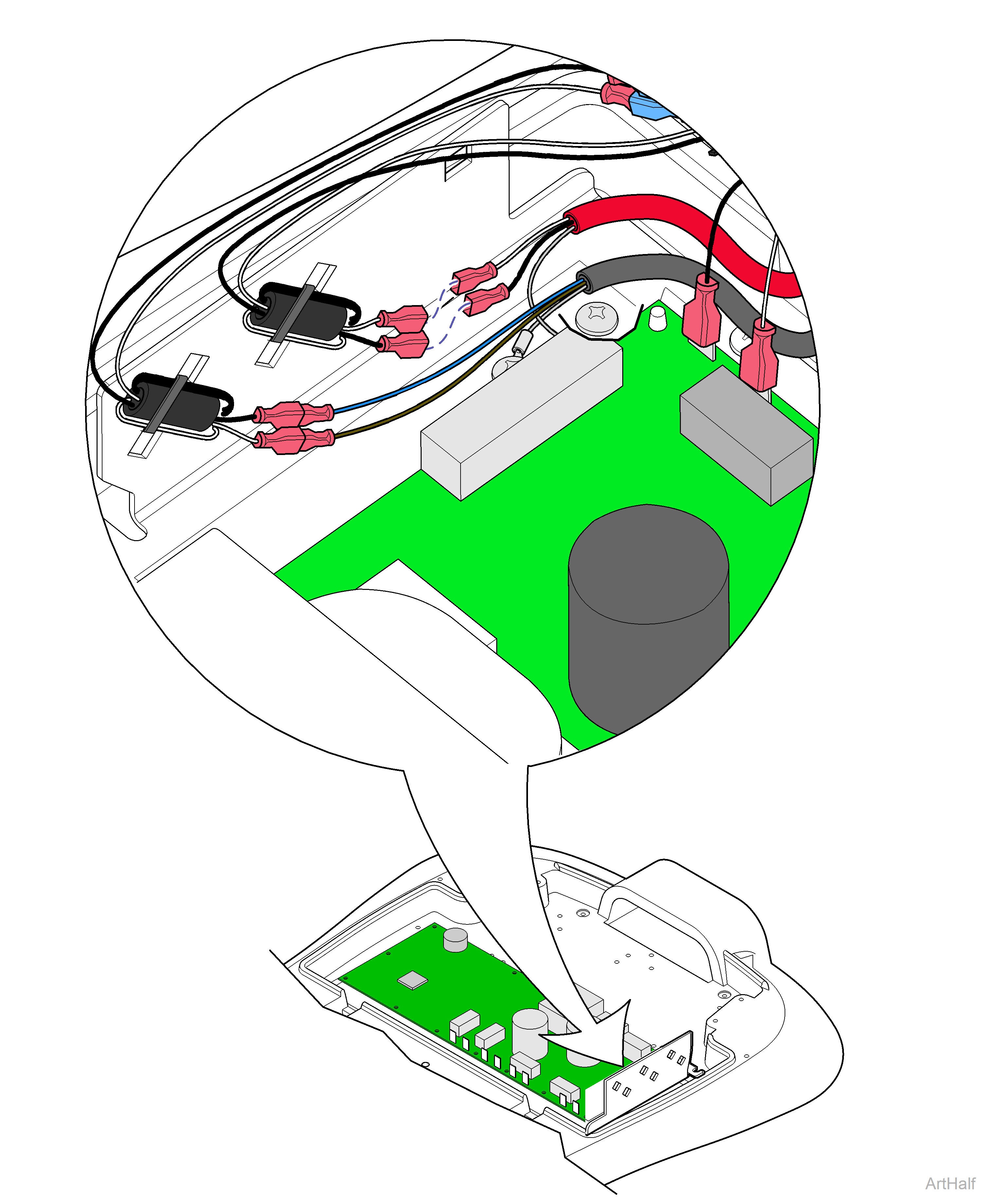
This illustration shows the three serviceable components of the base actuator. Use the table below to isolate the malfunction.
|
Problem |
Required Action |
|---|---|
|
Motor runs, but makes grinding noise |
Clean / lube actuator threads, Replace actuator if necessary |
|
Motor runs, but chair does not move |
Inspect / replace motor coupler |
|
Motor does not run |
Perform Actuator Motor Test |
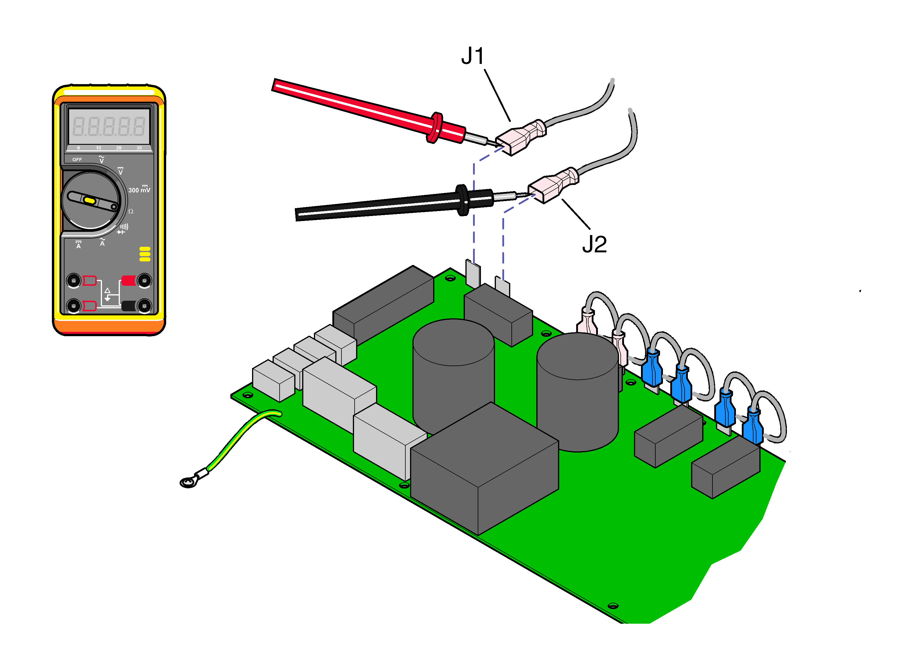
1.Tag, then disconnect base actuator wires J1 and J2.
2.Place meter probes on actuator wires. Check meter reading.
|
Meter Reading |
Status |
Required Action |
|---|---|---|
|
1 to 10 Ω |
|
Actuator motor OK, Perform Motor Ground Test |
|
OL or less than 1 Ω |
|
Replace motor |

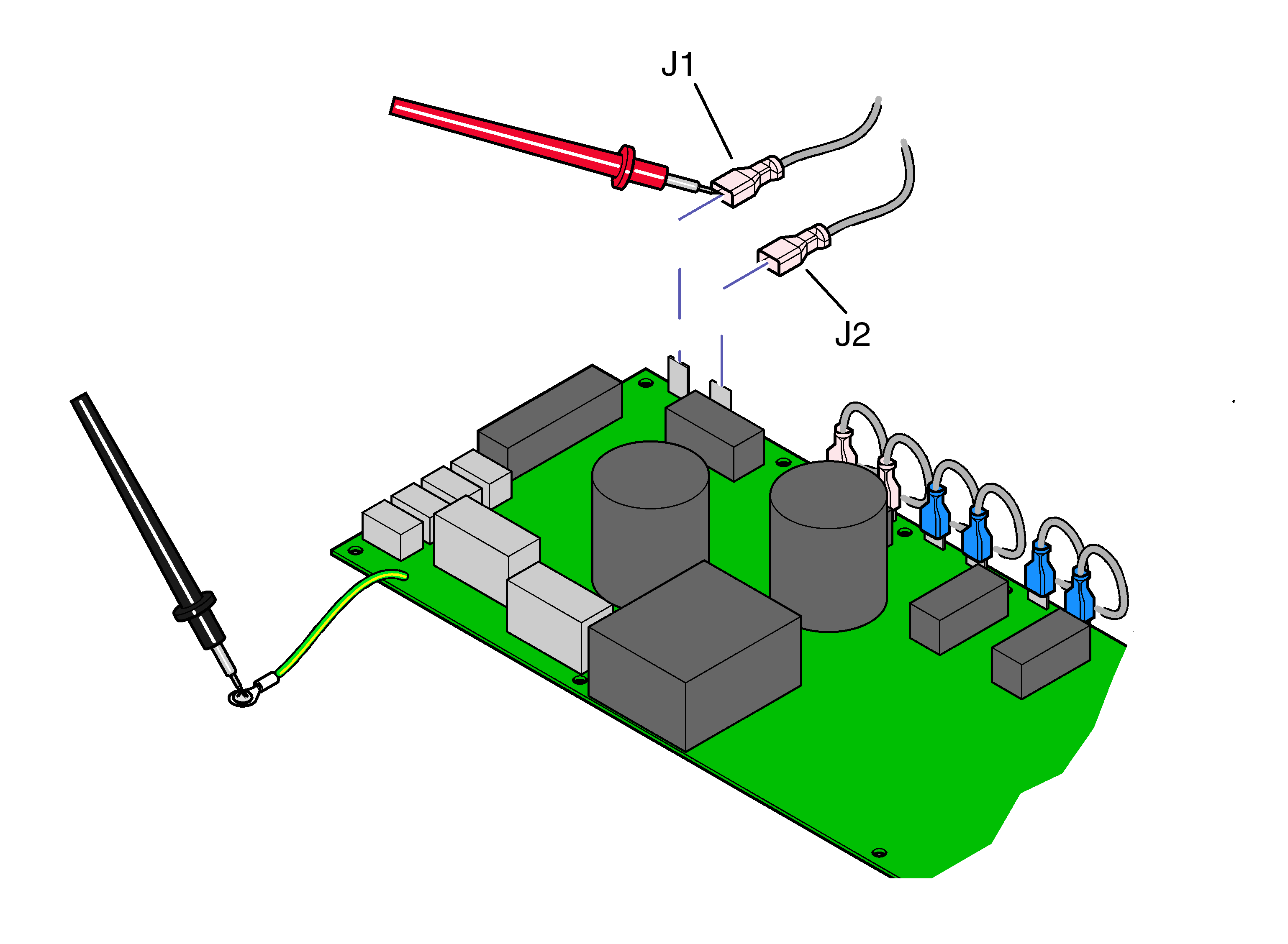
1.Place one meter probe on actuator wire J1. Place other meter probe on PC board ground wire. Check meter reading. Repeat for J2.
|
Meter Reading |
Status |
Required Action |
|---|---|---|
|
OL or more than 1 M Ω |

|
Motor harness OK, Perform PC Board Test |
|
Less than 1 Ω |
|
Replace motor |
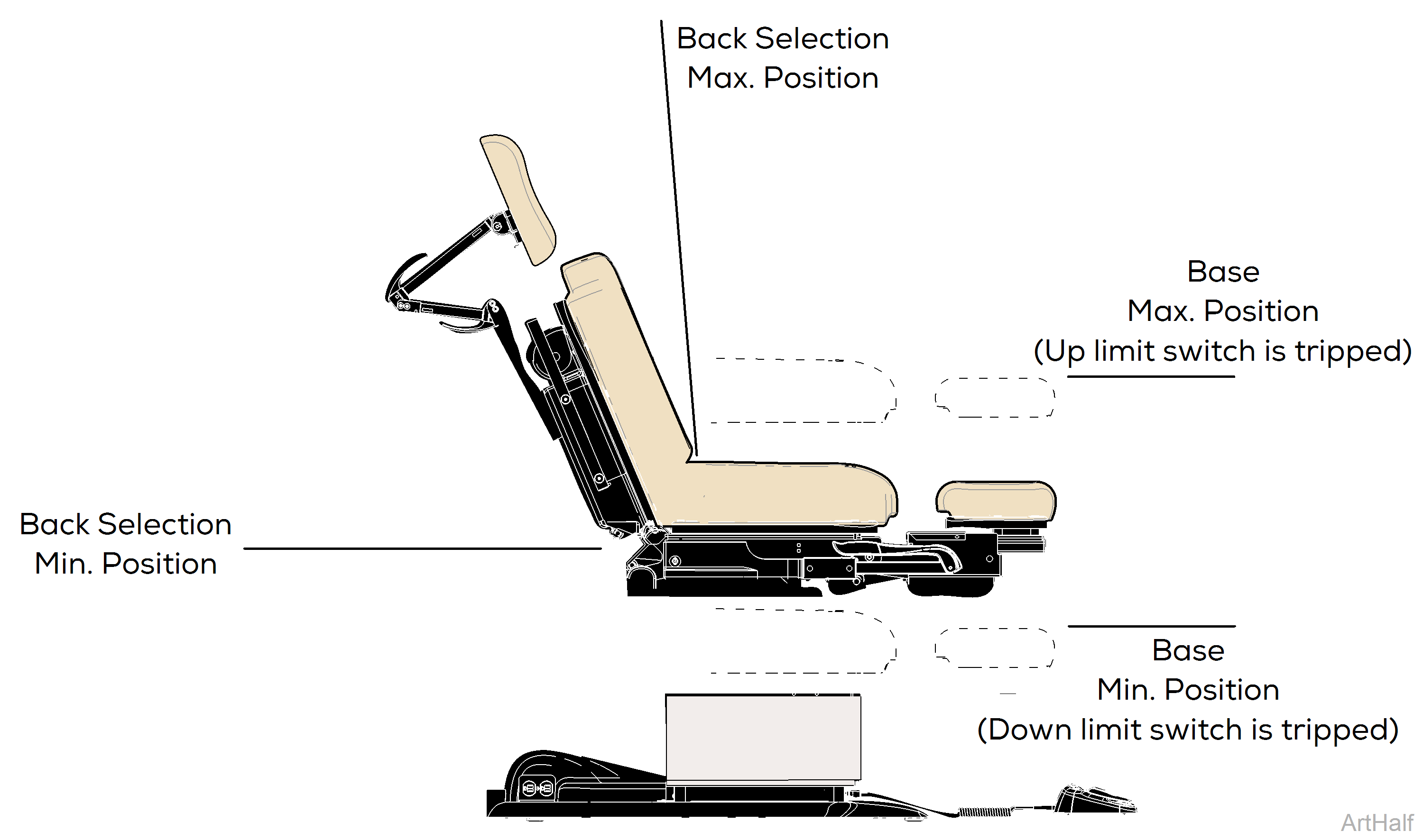
1.Move Back section so that it is approximately halfway between its maximum and minimum positions.
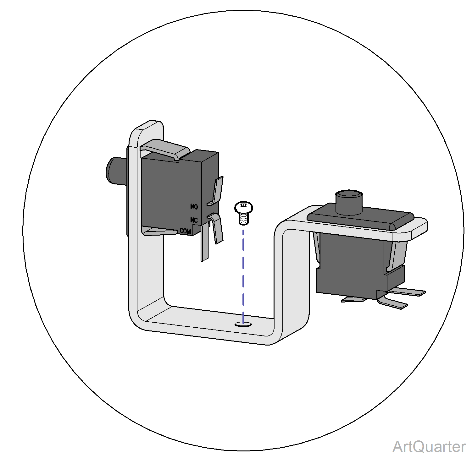
2.This test cannot be performed if either base limit switch is tripped. If necessary, remove switch bracket. Switch wires must remain connected.
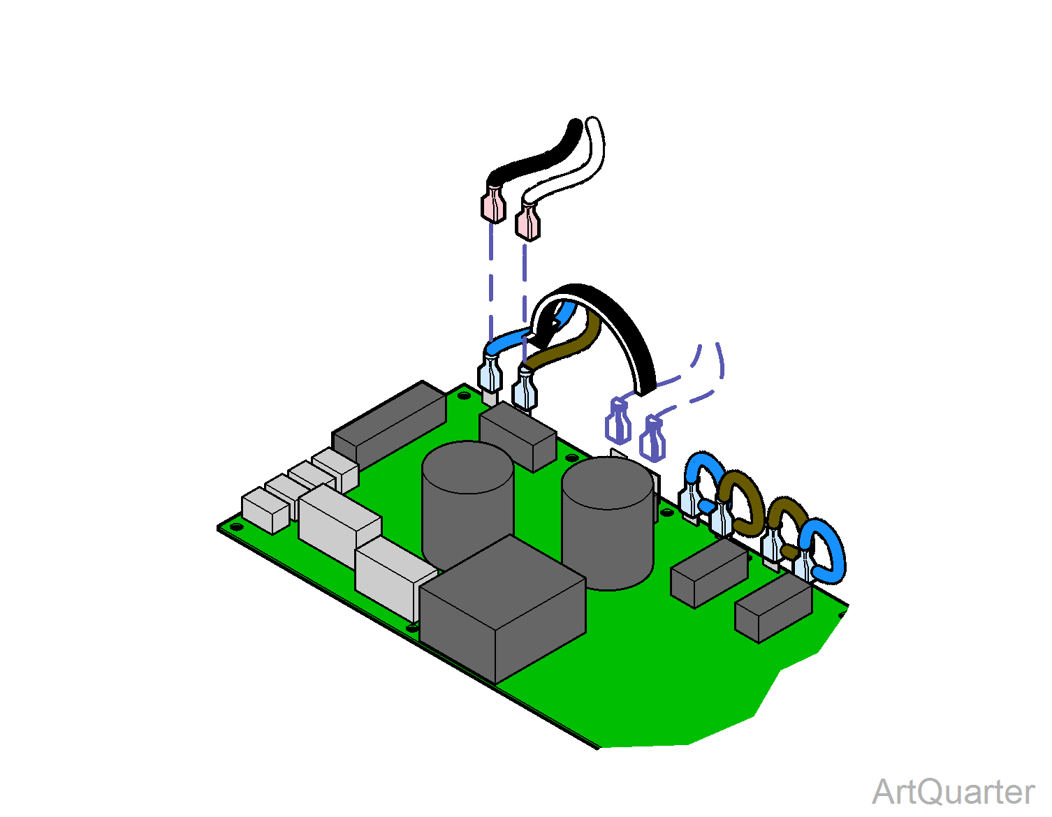
3.Disconnect base actuator wires from J1 and J2.
4.Move blue wire from J3 to J1. Move brown wire from J4 to J2.
The back limit switches will not stop movement during this test. Do not run past max. / min. positions.
5.Press and hold Base Up button on the hand or foot control for 5 seconds. Does back section move up briefly, then stop and beep? If Yes, go to Step 6. If No, replace PC Board.
6.Press and hold Base Down button on the hand or foot control for 5 seconds. Does back section move down briefly, then stop and beep? If Yes, PC Board is OK. If No, replace PC Board.
Remove and replace cable ties and wire clamps as necessary.
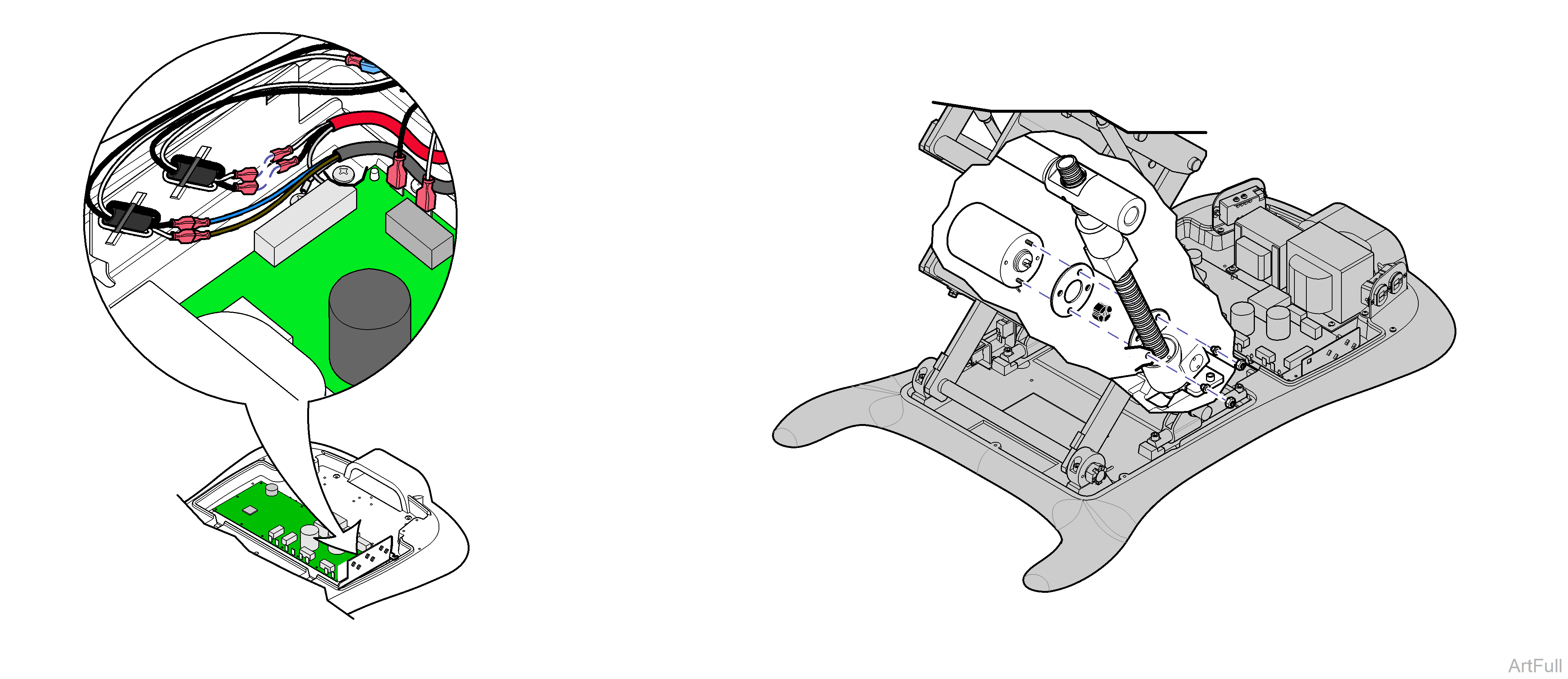
1.Raise base as high as possible.
2.Disconnect base actuator wires from choke harness. Disconnect ground wire.
3.Remove two nuts, motor, gasket, and coupler.
1.Install coupler, gasket, and motor. Secure with two nuts.
2.Connect actuator wires to choke harness, white to white, black to black. Connect ground wire.
1.Run Base Up function to maximum height.
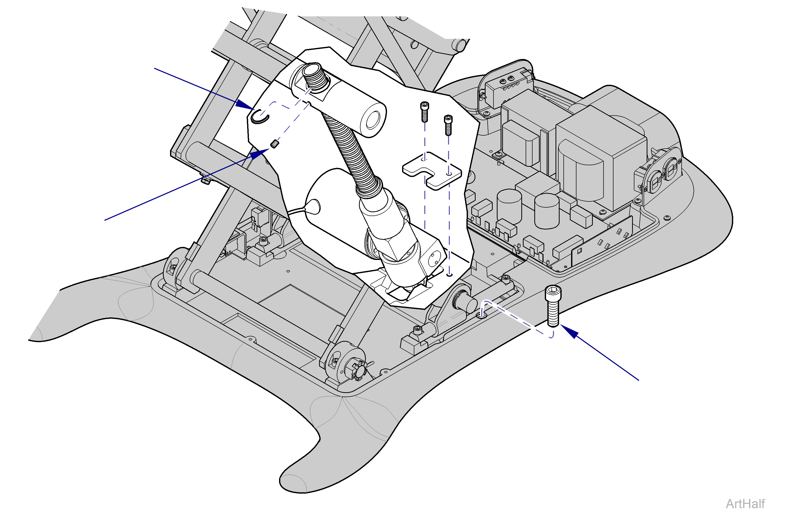
2.Install the Stop Bolt, included w/actuator kit.
The gas springs may support the full weight of the chair, but the stop bolt is still required to ensure safety.
3.Disconnect base actuator wires from choke harness. Disconnect ground wire.
Remove cable ties and wire clamps as necessary.
4.Remove retaining ring. Loosen set screw.
5.Manually rotate the collar and block to the bottom of the actuator shaft.
6.Remove retainer plate and actuator.
1.Insert actuator shaft thru hole. Position actuator with bottom pin in slot.
2.Manually rotate the collar and block to the top of the actuator shaft.
3.Push chair top down, until top of collar sticks thru cross bar.
4.Install retaining ring. Tighten set screw.
5.Install retainer plate and secure with screws.
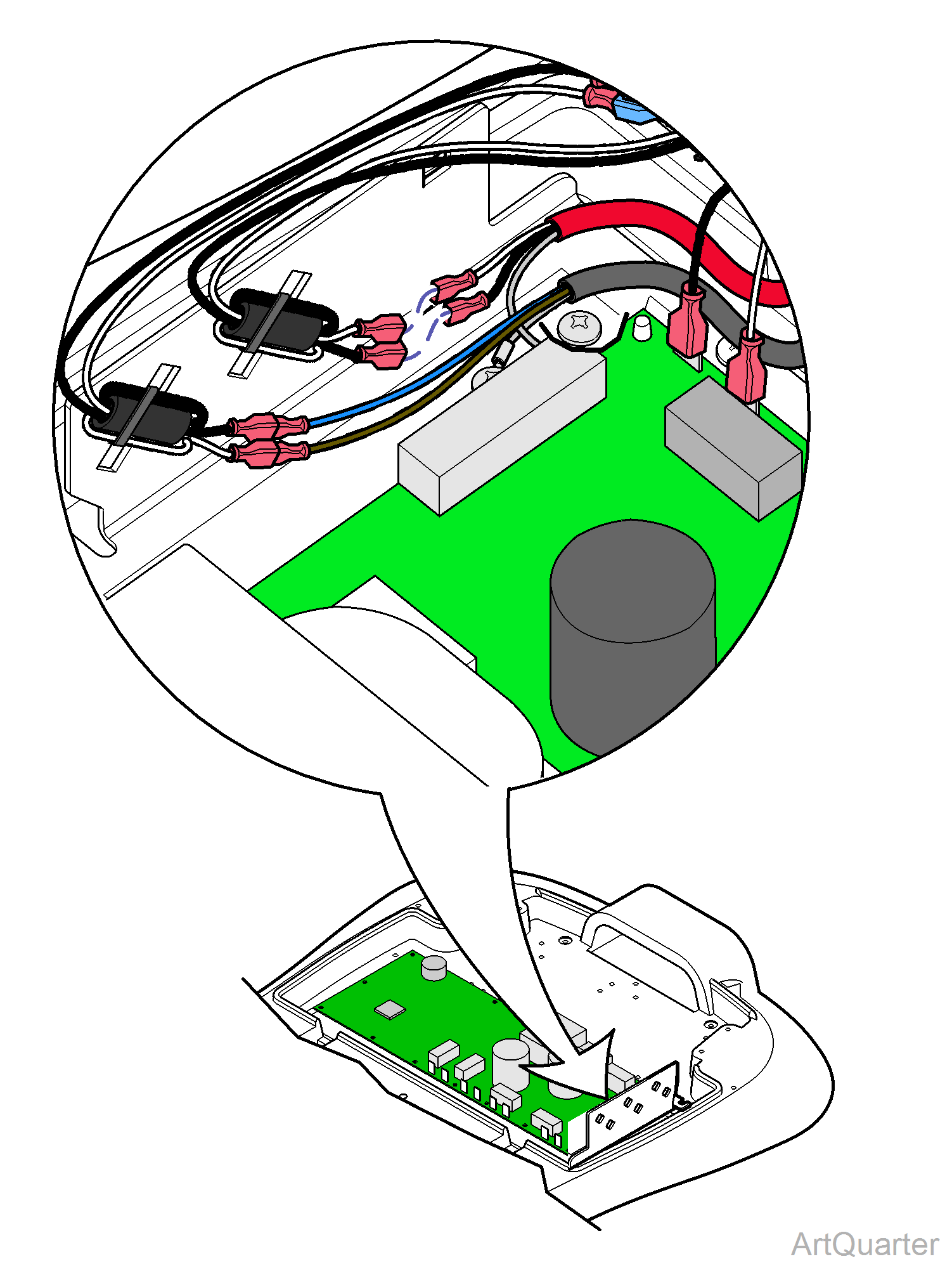
6.Connect actuator wires to choke harness, white to white and black to black. Connect ground wire.
Replace all cable ties and wire clamps. Raise chair and remove stop bolt.
