230 Universal Procedures Chair Main PC Board Test and Repair
If the PC Board detects a malfunction in the electrical system, the two Error Code LEDs on the PC Board will flash in a specific sequence to identify the cause of the problem.
1.Remove PC Board cover / locate Error Code LEDs
2.Press hand/foot control button for desired function.
If an electrical malfunction is detected:
•Function will stop moving.
•You will hear a beep.
•Error Code LEDs will flash error code sequence.
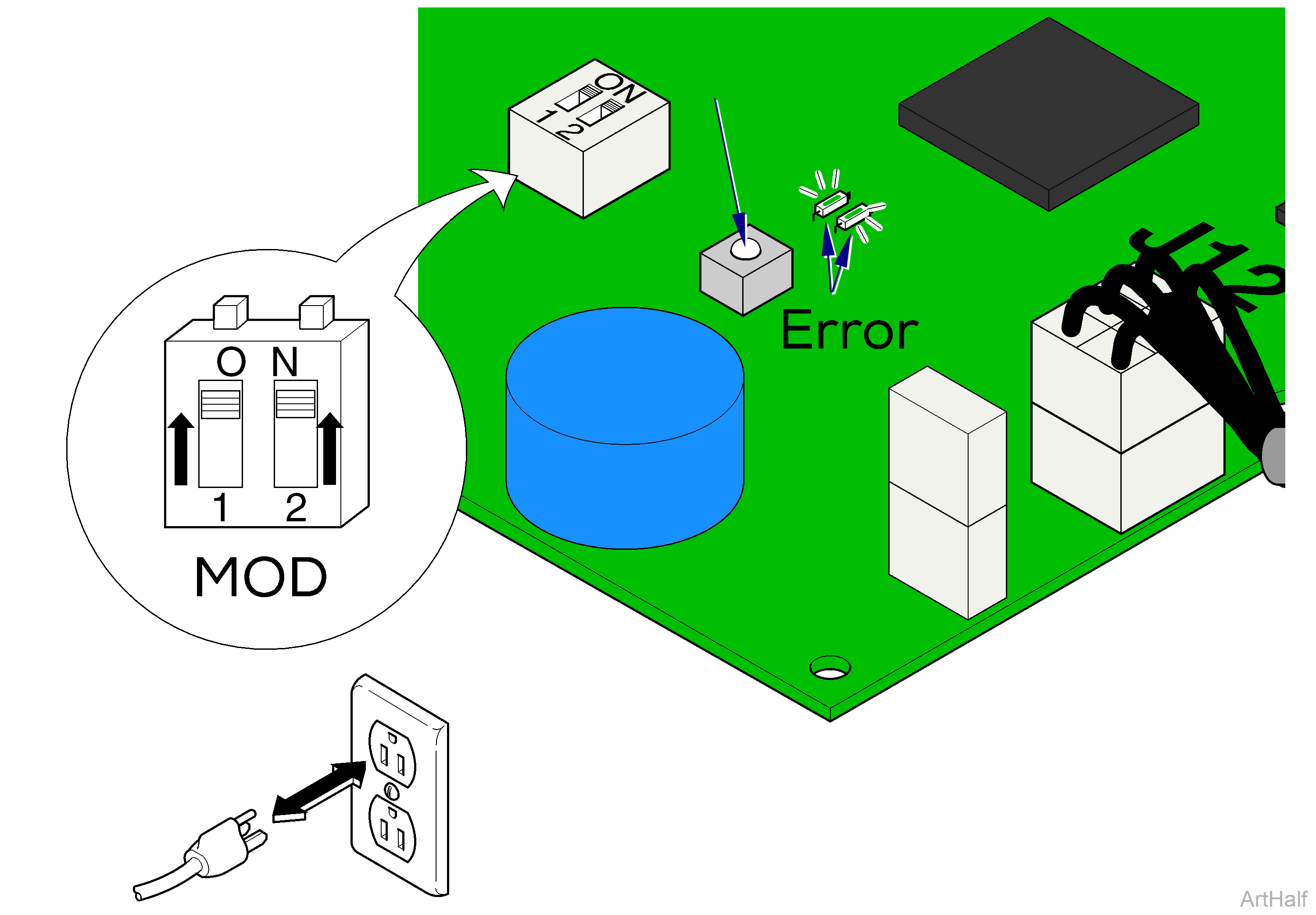
1.Move both Mode Select switches to On (up).
2.Unplug chair to reset PC Board, then plug back in.
3.Press and release S2 Button. To repeat error codes, press S2 Button again. To erase all error codes from memory, press and hold S2 Button until you hear three beeps.
If there are error codes stored in the system memory, Error Code LEDs will flash the sequence of the five most recent error codes. You will hear three "beeps" between each error code.
1.Move Mode Select block switches back to original position.
2.Unplug chair to reset board.
3.Plug chair back in.
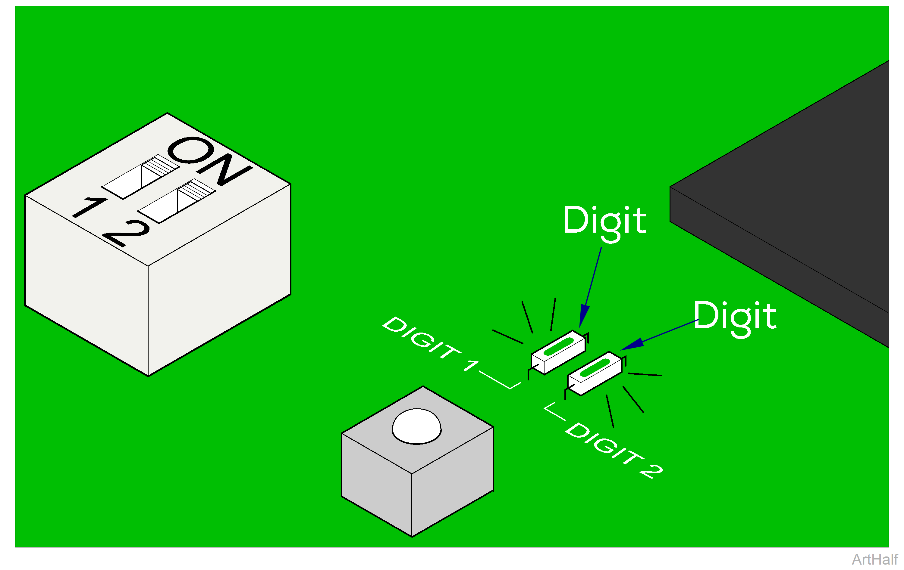
Digit 1 LED
Digit 1 LED identifies the function or mode during which the error was detected. Ex. Base / Back / Tilt / Foot, Programming Mode, Calibration Mode, Software System. Record the number of times this LED flashes before Digit 2 LED begins to flash.
Digit 2 LED
Digit 2 LED identifies cause of the error. Ex. actuator motor overload, treatment pan out, etc. Record the number of times this LED flashes before Digit 1 LED flashes again.
Locate the two digit error code in the charts below:
|
# of flashes Digit 1 LED |
Chair Function |
# of flashes Digit 2 LED |
Cause of the Error |
|---|---|---|---|
|
1 |
Base |
1 |
Function in potential crash position |
|
2 |
Back |
2 |
Actuator motor run time exceeded max. limit |
|
3 |
Tilt |
3 |
Position sensor did not move when function was activated |
|
4 |
Foot |
4 |
Position sensor reading is out of acceptable range |
|
5 |
not used |
5 |
Actuator motor overload |
|
6 |
not used |
6 |
Function failed during calibration |
|
7 |
Programming Mode |
1 |
Position Button (1,2,3, or 4) not pressed within 5 seconds. |
|
2 |
Incorrect button pressed while in Programming Mode. |
||
|
3 |
Position cannot be programmed (possible "crash" position) |
||
|
8 |
Calibration Mode |
1 |
Calibration was not successful |
|
|
|
2 |
Incorrect button pressed while in Calibration Mode. |
|
|
Error Recall Mode |
3 |
Incorrect button pressed while in Error Recall Mode. |
|
9 |
Software System |
1 |
Software malfunction |
|
2 |
Software malfunction |
||
|
3 |
Software malfunction |
||
|
4 |
Foot Up function activated w/ Treatment Pan pulled out |
||
|
5 |
Hand/foot control button pressed while in Child Lock-Out Mode |
||
|
9 |
Disregard this error. |
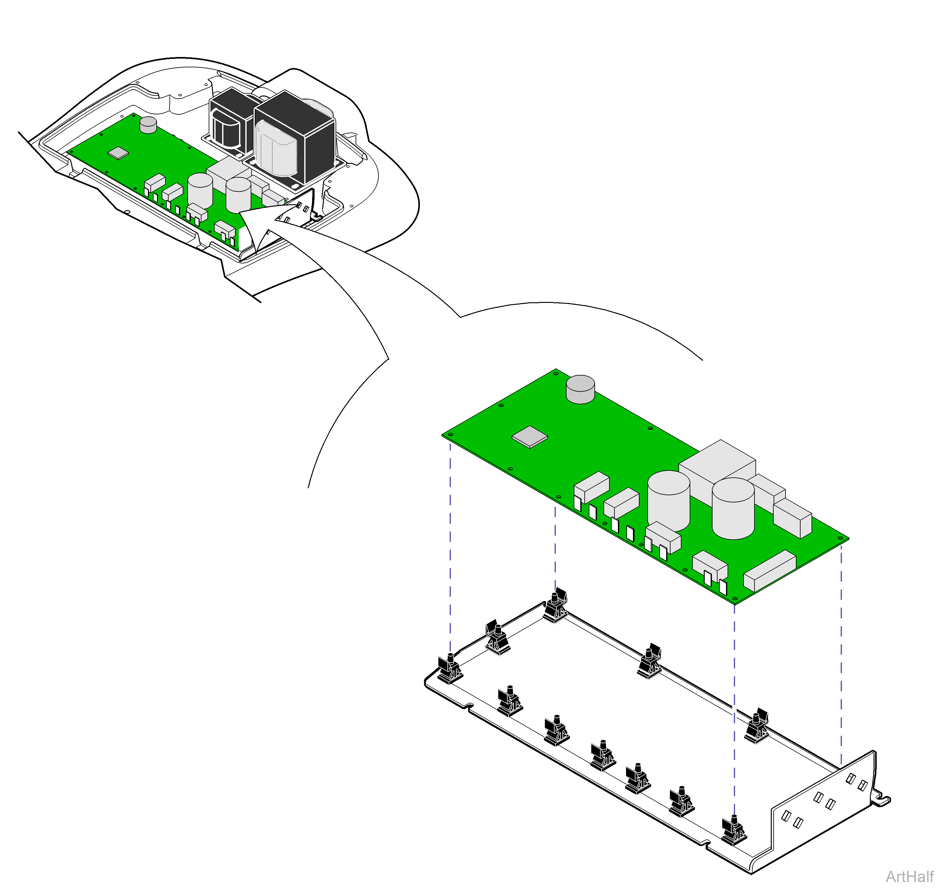
1.Tag and disconnect all wire harnesses from board.
2.Push tabs back and remove board from mounting studs.
1.Align board with mounting studs, then press down until tabs lock board in place.
To minimize stress on the board, work from one end to the other.
2.Connect all wire harnesses to proper terminals.
3.Midmark models only! Perform Calibration Procedure.
This must be performed any time PC Board is disconnected.
