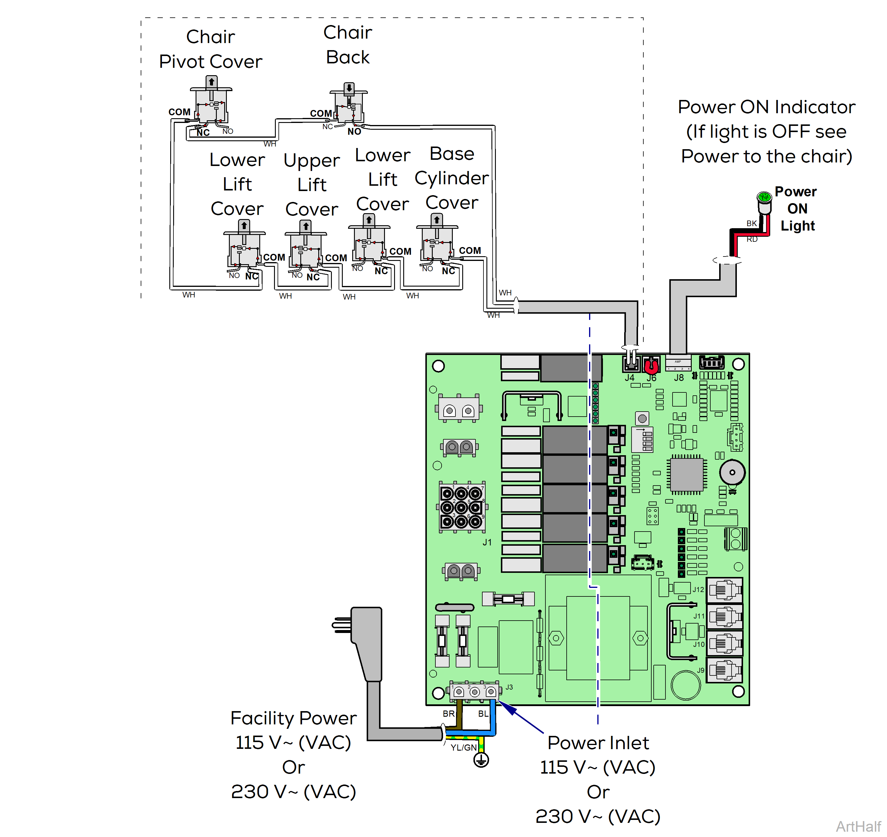
Elevance® Chair Collision Protection System and the Home Function Theory of Operation
This illustration shows the safety bail limit switches involved in this system.
How Safety Bail Limit Switches Work
Switches can be used as Normally Open or Normally Closed devices. The switch name describes the rest (normal) state. The active state is opposite the normal state.
Normally Closed (NC) Switch
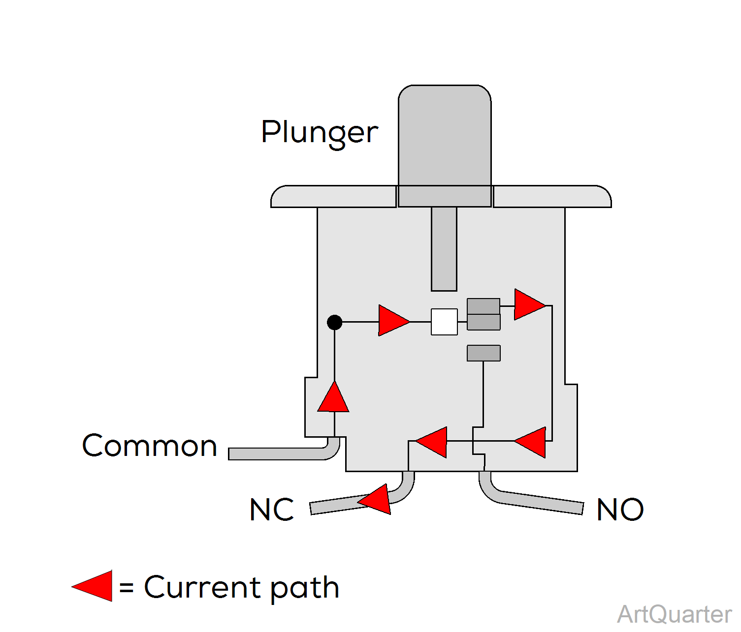
| Switch State | Physical Status | Current Flow |
|---|---|---|
|
Normal (shown) |
Plunger Up | Current flows thru switch and exits NC path. |
|
Active |
Plunger Down | Current flows into switch and exits NO path |
Normally Open (NO) Switch
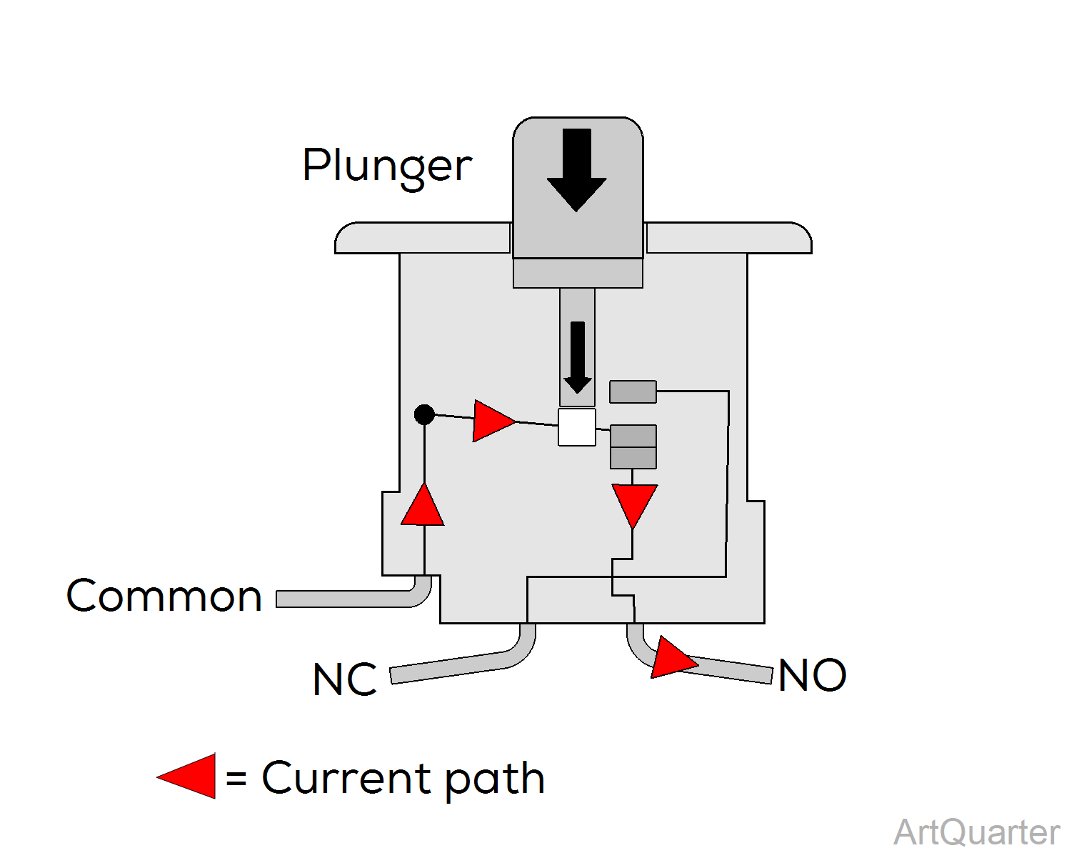
| Switch State | Physical Status | Current Flow |
|---|---|---|
|
Normal (shown) |
Plunger Down | Current flows into switch and exits NO path. |
| Active | Plunger Up | Current flows thru switch and exits NC path |
The system
The chair has six safety bail limit switches wired in series mounted in these areas:
•Lower Pivot Cover
•Upper Lift Arm Cover
•Lower Lift Arm Cover (right and left sides)
•Base Cylinder Cover
•Chair Back
All of these switches are normally closed switches except for the Chair Back switch, which is a normally open switch.
How functions are disabled
1.When a cover equipped with a normally closed switch makes contact with an object as the base is moving downward, the switch opens.
2.When the back makes contact with an object as the back is moving downward, the switch actuator bracket moves away from the normally open switch, closing it.
When any safety bail switch moves out of its normal position, power is removed from the Base and Back Down Hydraulic Valve Bank solenoids.
After an obstruction is hit, the base (or back) stops lowering and raises a little so the object can be removed.
How are functions resumed
1.Release the down control button.
2.Remove the object obstructing downward movement.
3.Press control buttons to resume operation.
The Home Function
The home position is a software directed base height, back up position convenient for installation procedures or patient access.
Tap any lift arm or a pivot cover three times to activate the home function.
The chair beeps as it moves and stops beeping when it reaches the home position.
Relevant voltage readings:
•115 V~ (VAC) at J3, Power inlet. Read pins 1 & 3
•12 V (VDC) at J4 Limit Switch Connector
LED indicators:
Look at LED D17 to read status of all safety bail switches .
LED ON = all switches are in normal state
LED OFF = one or more switches is active
The PC Board constantly monitors safety limit switches and sensory devices on the chair.
The Collision Protection System activates when a chair cover equipped with a safety limit switch hits an object as it is moving down.
The chair stops and raises slightly to disengage contact; The chair also beeps until the control button is released.
Normal operation can resume once the object is removed and the safety limit switch becomes inactive.
