Elevance® Chair Rotational Brake and Lockout Theory of Operation
This illustration shows only the rotational brake components.
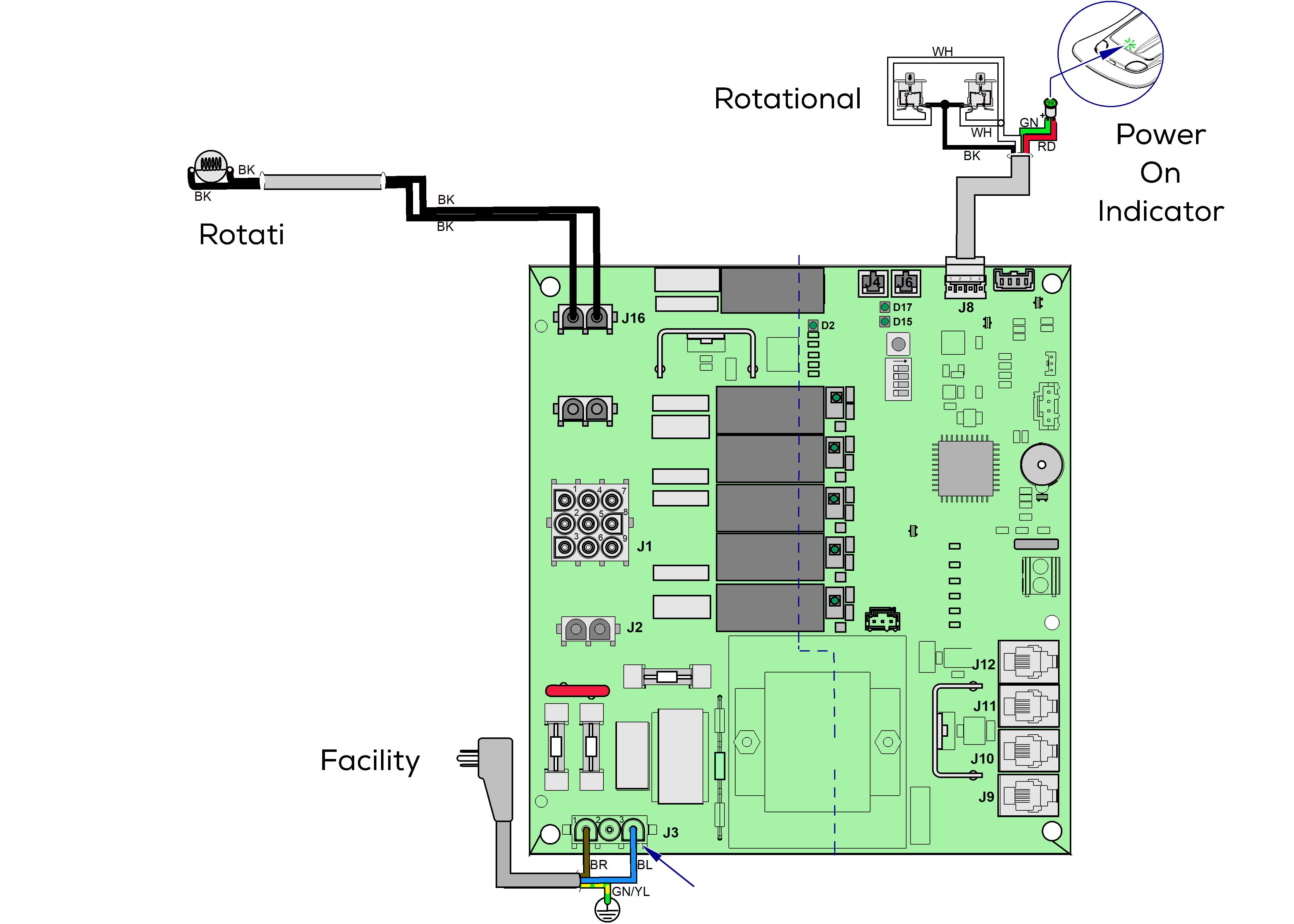
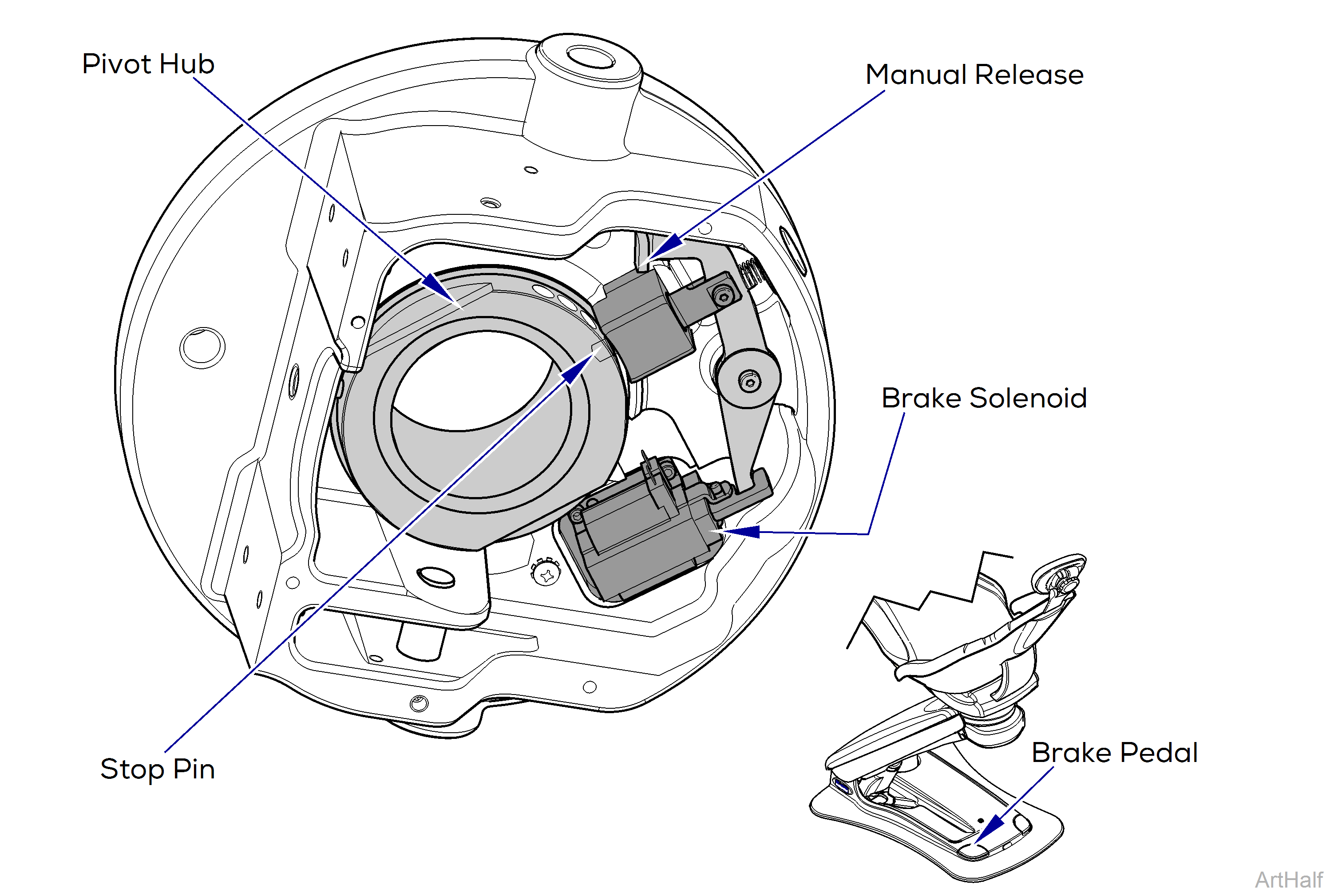
An electric rotational brake holds the chair in place by inserting a stop pin into one of a series of holes spaced around the pivot hub. A software controlled lockout feature completely locks out all chair movement when activated.
The system
Stepping on either brake release pedal on the chair base frame, closes a limit switch enabling the brake solenoid to activate, drawing in the stop pin and allowing the chair to rotate freely.
When the brake release pedal is released, the solenoid releases the spring-loaded stop pin, allowing it to pop into the next hole it comes to in the pivot hub.
Lockout Feature
A lockout feature is provided to disable all electronic controls on the chair to prevent unintentional use.
To activate the lockout feature, press either of the brake release pedals five times in succession. The chair beeps five times to indicate it is locked out. Buttons on control devices and the brake release pedals will no longer work.
To release the lockout feature, press either of the brake release pedals five times in succession. The chair again beeps five times to indicate it is unlocked. Buttons on control devices and the brake release pedals will function normally again.
Relevant voltage readings:
•115 V~ (VAC) at J3, Power inlet. Read pins 1 & 3
•115 V~ (VAC) at J16, Rotational Brake Read pins 1 & 2
•12 V (VDC) at J8, for Power Light and Brake Limit Switches
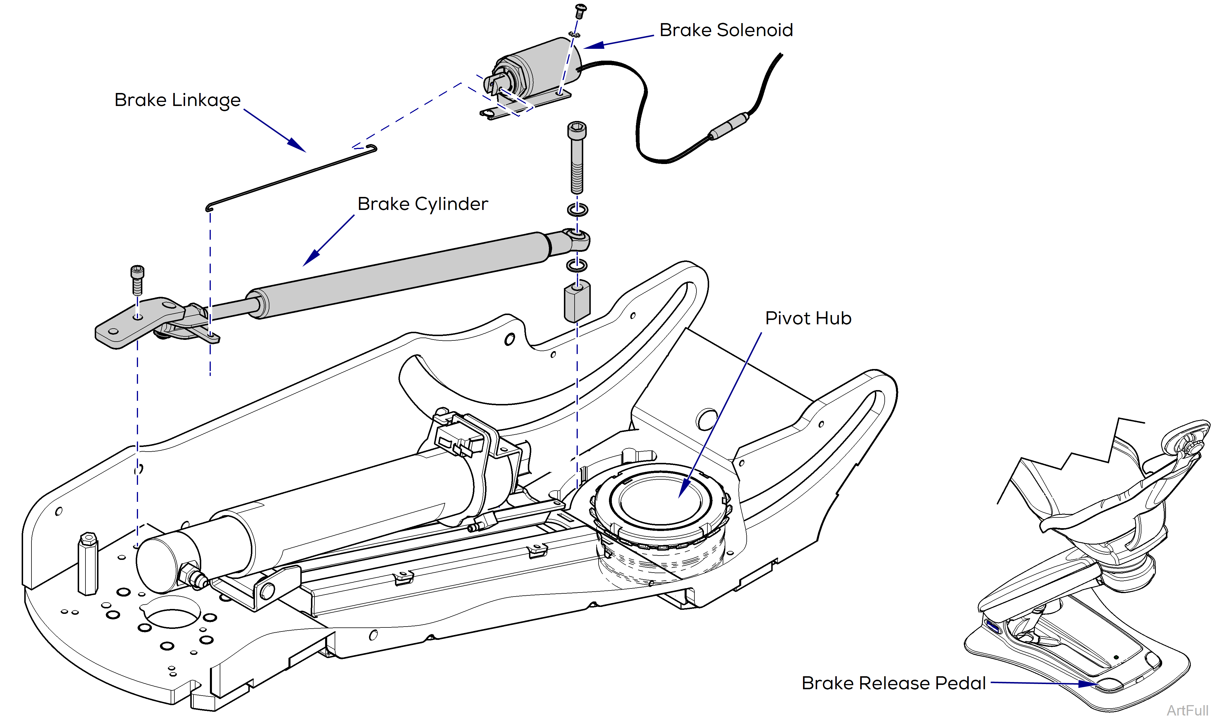
An mechanical cylinder holds the chair rotation in place. A software controlled lockout feature completely locks out all chair movement when activated.
The system
Stepping on either brake release pedal on the chair base frame, closes a limit switch enabling the brake solenoid to activate, moving linkage to activate the button at the end of the cylinder allowing the piston to extend and retract enabling the chair to rotate.
When the brake release pedal is released, the solenoid returns linkage to the original position with no pressure on cylinder button the piston is unable to extend or retract locking the chair rotation.
Lockout Feature
A lockout feature is provided to disable all electronic controls on the chair to prevent unintentional use.
To activate the lockout feature, press either of the brake release pedals five times in succession. The chair beeps five times to indicate it is locked out. Buttons on control devices and the brake release pedals will no longer work.
To release the lockout feature, press either of the brake release pedals five times in succession. The chair again beeps five times to indicate it is unlocked. Buttons on control devices and the brake release pedals will function normally again.
Relevant voltage readings:
•115 V~ (VAC) at J3, Power inlet. Read pins 1 & 3
•115 V~ (VAC) at J16, Rotational Brake. Read pins 1 & 2
•12 V (VDC) at J8, for Power Light and Brake Limit Switches
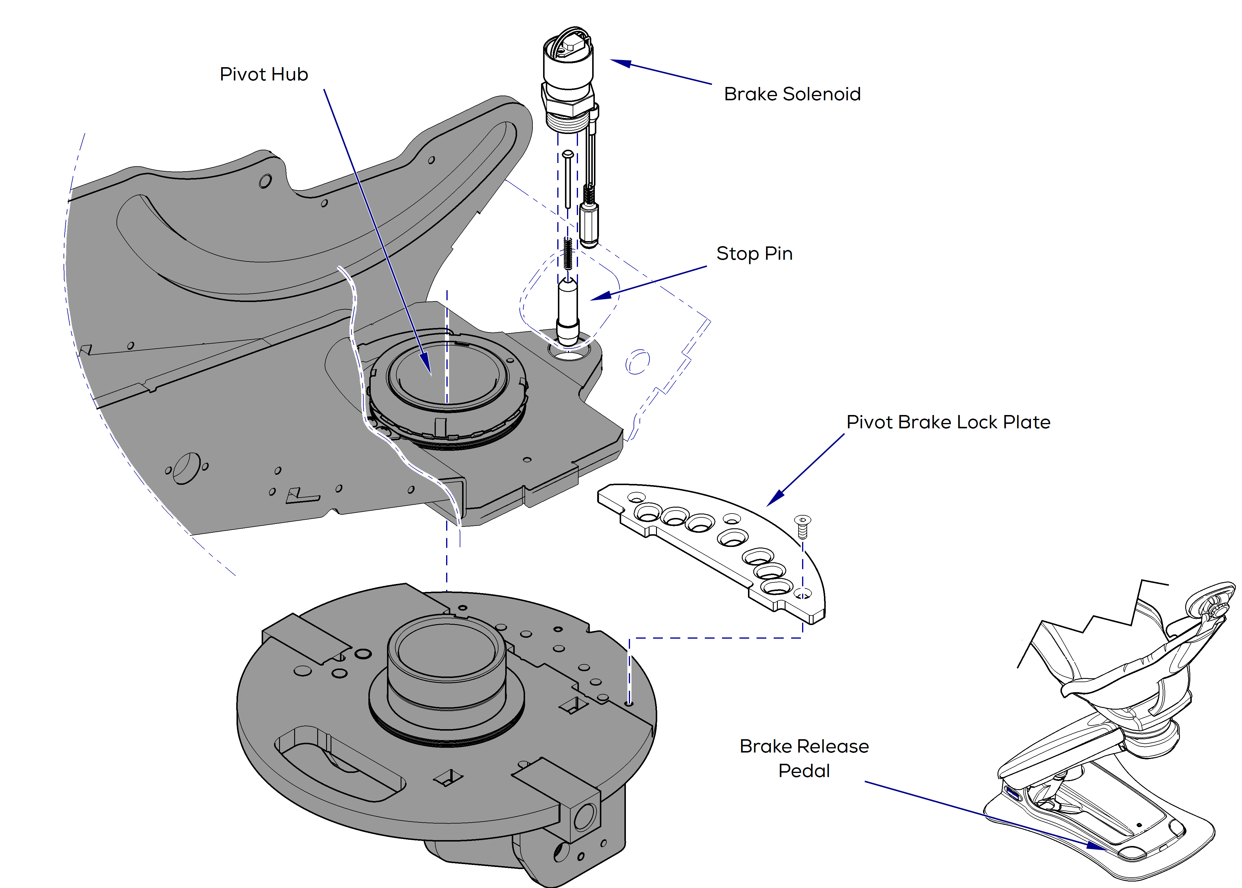
An electric rotational brake holds the chair in place by inserting a stop pin into one of a series of slots spaced around the pivot brake lock plate. A software controlled lockout feature completely locks out all chair movement when activated.
The system
Stepping on either brake release pedal on the chair base frame, closes a limit switch enabling the brake solenoid to activate, drawing up the stop pin and allowing the chair to rotate freely.
When the brake release pedal is released, the solenoid releases the spring-loaded stop pin, allowing it to pop into the next slot it comes to in the pivot brake locking plate.
Lockout Feature
A lockout feature is provided to disable all electronic controls on the chair to prevent unintentional use.
To activate the lockout feature, press either of the brake release pedals five times in succession. The chair beeps five times to indicate it is locked out. Buttons on control devices and the brake release pedals will no longer work.
To release the lockout feature, press either of the brake release pedals five times in succession. The chair again beeps five times to indicate it is unlocked. Buttons on control devices and the brake release pedals will function normally again.
Relevant voltage readings:
•115 V~ (VAC) at J3, Power inlet. Read pins 1 & 3
•115 V~ (VAC) at J16, Rotational Brake. Read pins 1 & 2
•12 V (VDC) at J8, for Power Light and Brake Limit Switches
