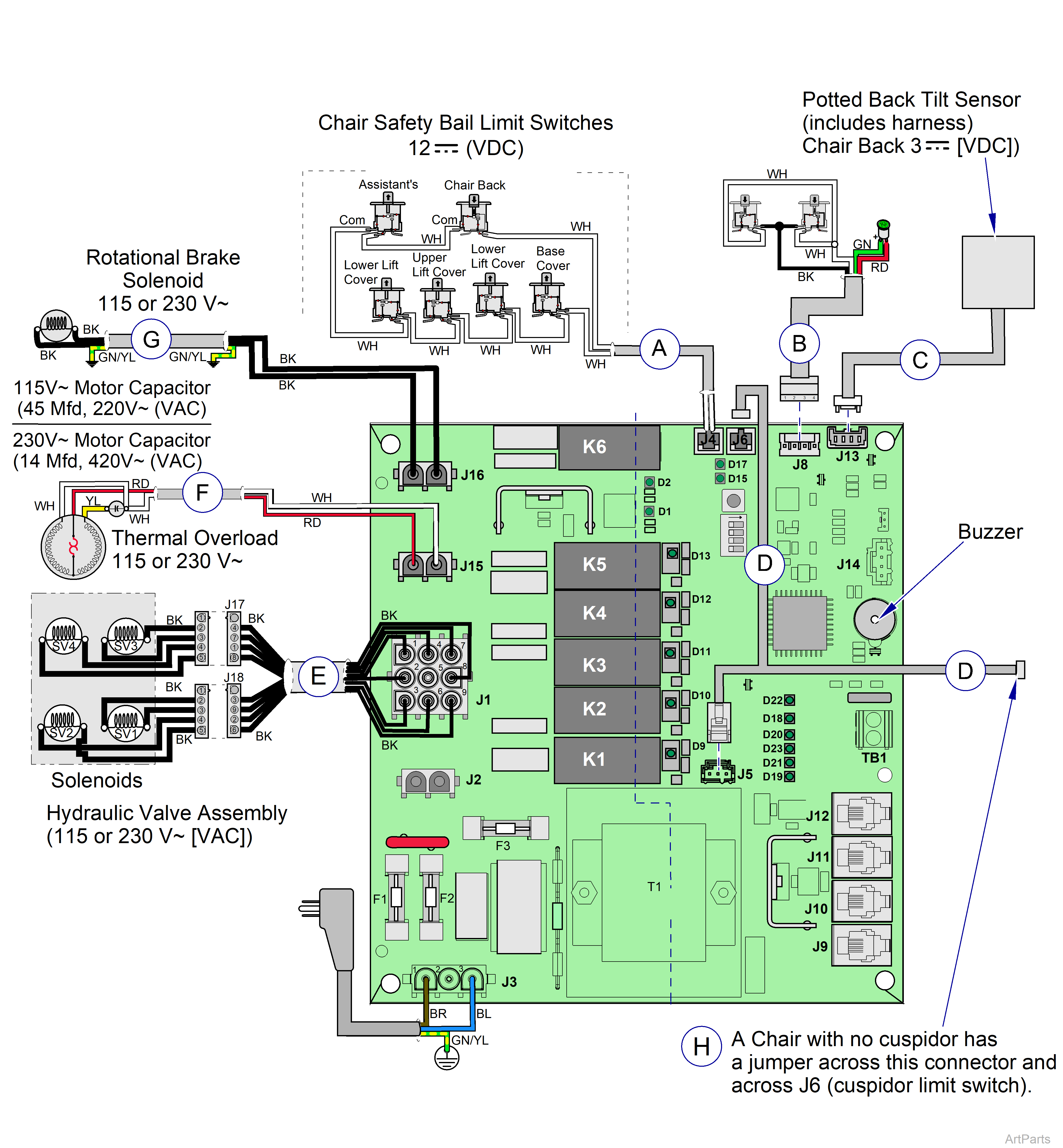
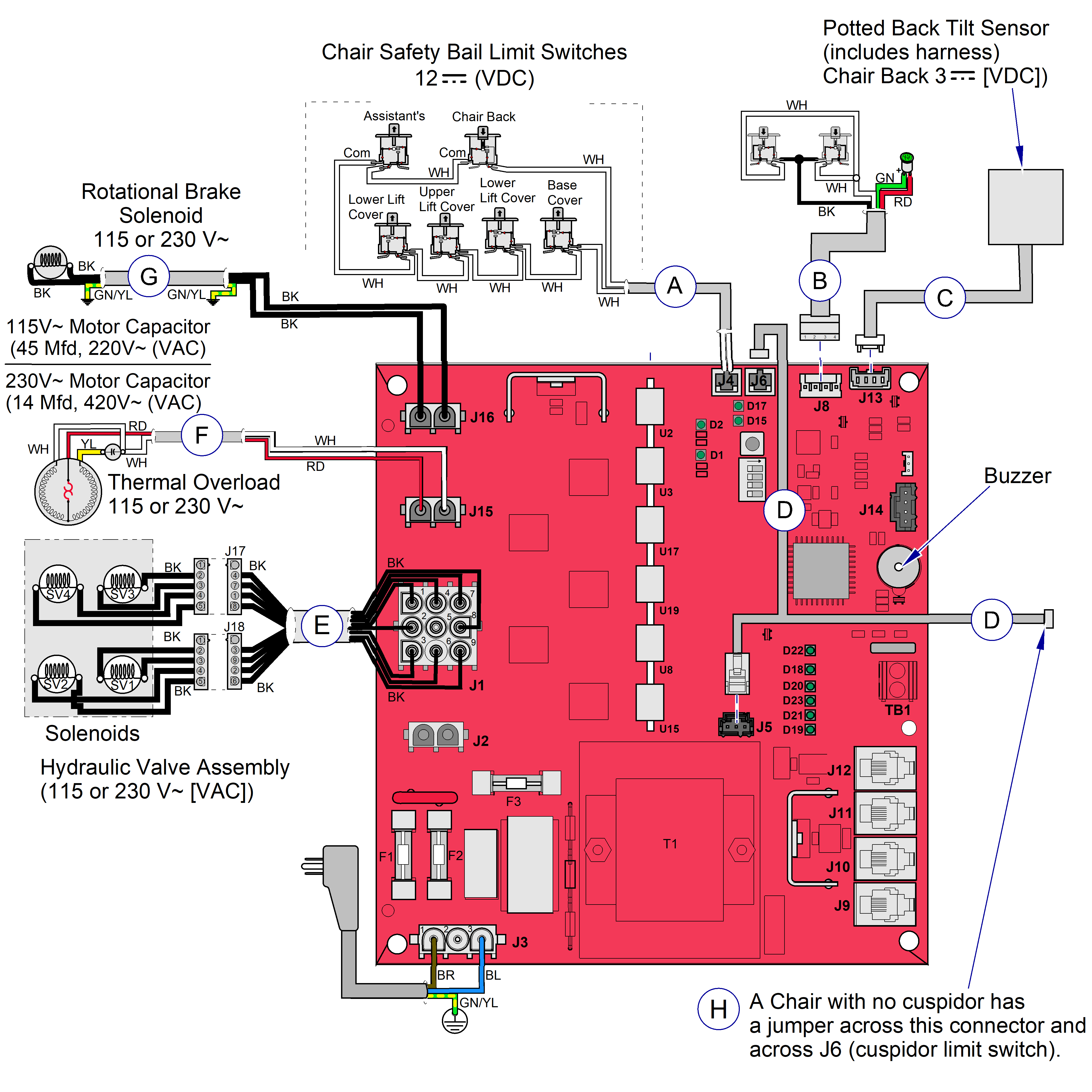
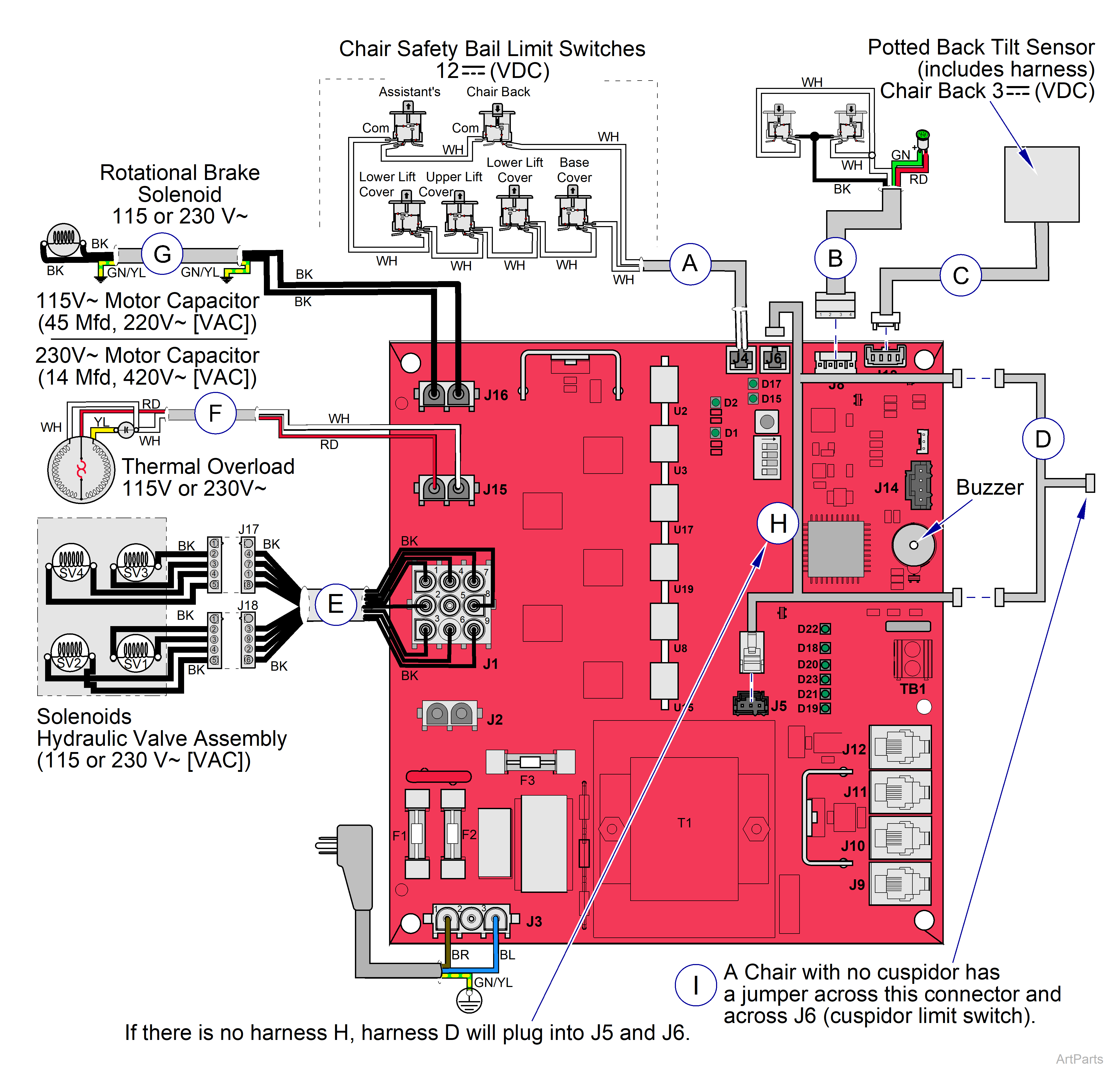
Elevance® Chair PC Board and Harnesses Wiring Diagram
|
Model |
153810 |
| Serial Number | Prior to V2475009 |
| Item | Part Number | Description |
|---|---|---|
|
A |
015-2239-00 | Safety Bail Harness |
|
B |
015-2237-00 | Brake Release / Power Light Harness |
|
C |
015-3015-01 | Potted Back Tilt Sensor |
|
D |
015-2323-00 | Cuspidor Power / Limit Switch Harness |
|
E |
015-2321-00 | Solenoid Adapter Harness |
|
F |
015-2320-00 | Pump Adapter Harness |
|
G |
015-2319-00 | Rotational Brake Solenoid Harness |
|
H |
015-1478-00 | Jumper - not shown - Used on Chairs with NO Cuspidor |
| Color Abbreviation Chart | ||
|
NSS = Not Sold Separately | AR = As Required | NLA = No Longer Available | CFN = Call for Number Always Specify Model and Serial Number |
||
PC Board Information - Output LEDs
| Outputs | PC Board Description | LED |
|---|---|---|
| K1 | Base Down | D9 |
| K2 | Base Up | D10 |
| K3 | Back Down | D11 |
| K4 | Back Up | D12 |
|
K5 Triac |
Pump-R Pump-T |
D13 D1 |
| K6 | Rotational Brake | D2 |
PC Board Information - Input LEDs
| Name | LED | Description |
|---|---|---|
| Brake | D15 | Comes on when the break pedal is pressed. |
| OK | D17 | Comes on when both limit switches J5 and J6 are closed. |
| * Foot Control | D22 | Optional component |
| Dental Light | D18 | Optional component |
| * Remote Control Base Station | D20 | Optional component |
| Assistant’s Unit Keypad | D21 | Optional component |
| Delivery Unit Keypad | D23 | Optional component |
| Extra | D19 | Available for additional options. |
| * One of these options is required | ||
J Connectors on the PC Board
| Connector | Description |
|---|---|
| J2 | Auxiliary Output (Line VAC) |
| J5 | Cuspidor Power and Rinse |
| J7 and J14 | Test Plugs for Factory Use Only |
| J9 thru 12 | Keypad Communication Lines |
| TB1 | Communication Terminal for non-chair mounted Lights |
|
Model |
153810 |
| Serial Number | After V2475010 |
| Item | Part Number | Description |
|---|---|---|
|
A |
015-2239-00 | Safety Bail Harness |
|
B |
015-2237-00 | Brake Release / Power Light Harness |
|
C |
015-3015-01 | Potted Back Tilt Sensor |
|
D |
015-2323-00 | Cuspidor Power / Limit Switch Harness |
|
E |
015-2321-00 | Solenoid Adapter Harness |
|
F |
015-2320-00 | Pump Adapter Harness |
|
G |
015-2319-00 | Rotational Brake Solenoid Harness |
|
H |
015-1478-00 |
Jumper - not shown - Used on Chairs with NO Cuspidor |
| Color Abbreviation Chart | ||
|
NSS = Not Sold Separately | AR = As Required | NLA = No Longer Available | CFN = Call for Number Always Specify Model and Serial Number |
||
PC Board Information - Output LEDs
| Outputs | PC Board Description | LED |
|---|---|---|
| U15 | Base Down | D9 |
| U8 | Base Up | D10 |
| U19 | Back Down | D11 |
| U17 | Back Up | D12 |
|
U3 |
Pump-T |
D2 |
| U2 | Rotational Brake | D1 |
PC Board Information - Input LEDs
| Name | LED | Description |
|---|---|---|
| Brake | D15 | Comes on when the break pedal is pressed. |
| OK | D17 | Comes on when both limit switches J5 and J6 are closed. |
| * Foot Control | D22 | Optional component |
| Dental Light | D18 | Optional component |
| * Remote Control Base Station | D20 | Optional component |
| Assistant’s Unit Keypad | D21 | Optional component |
| Delivery Unit Keypad | D23 | Optional component |
| Extra | D19 | Available for additional options. |
| * One of these options is required | ||
J Connectors on the PC Board
| Connector | Description |
|---|---|
| J2 | Auxiliary Output (Line VAC) |
| J5 | Cuspidor Power and Rinse |
| J7 and J14 | Test Plugs for Factory Use Only |
| J9 thru 12 | Keypad Communication Lines |
| TB1 | Communication Terminal for non-chair mounted Lights |
