Ultra Chair Hydraulic Solenoid Valve Assembly Test and Repair
1.Rotate seat to one side.
Unplug chair power cord before removing covers or working on chair. Failure to comply could result in personal injury.
2.Unplug chair power cord.
3.Remove covers, Refer to: Covers .
If either or both Base and/or Back sections are elevated, hydraulic pressure will be present in the line(s) between the cylinder(s) and Solenoid Valve Assembly. Pressure must be relieved before working on hydraulic system.
Use caution to prevent electrical shock with chair plugged into outlet. Electrical components and connections are exposed.
4.Remove pressure from an operable base cylinder:
a.Plug in chair power cord.
b.Depress the Base Down directional button on foot or membrane switch until base cylinder is at its lowest level.
c.Depress and hold down Program button while depressing Base Down directional button lowering base until it stops.
d.Unplug power cord.
5.Remove pressure from an inoperable base cylinder:
Use care to prevent damage to electrical leads and hydraulic lines when locating jack.
a.Lift up on chair slightly, using a jack, to take pressure off base cylinder.
On chairs that contain delivery head assembly, cuspidor and/or assistant’s console it may be necessary to locate the jack stand(s) in some other location. Assure the stands are positioned to securely support the load without damage to chair or accessories.
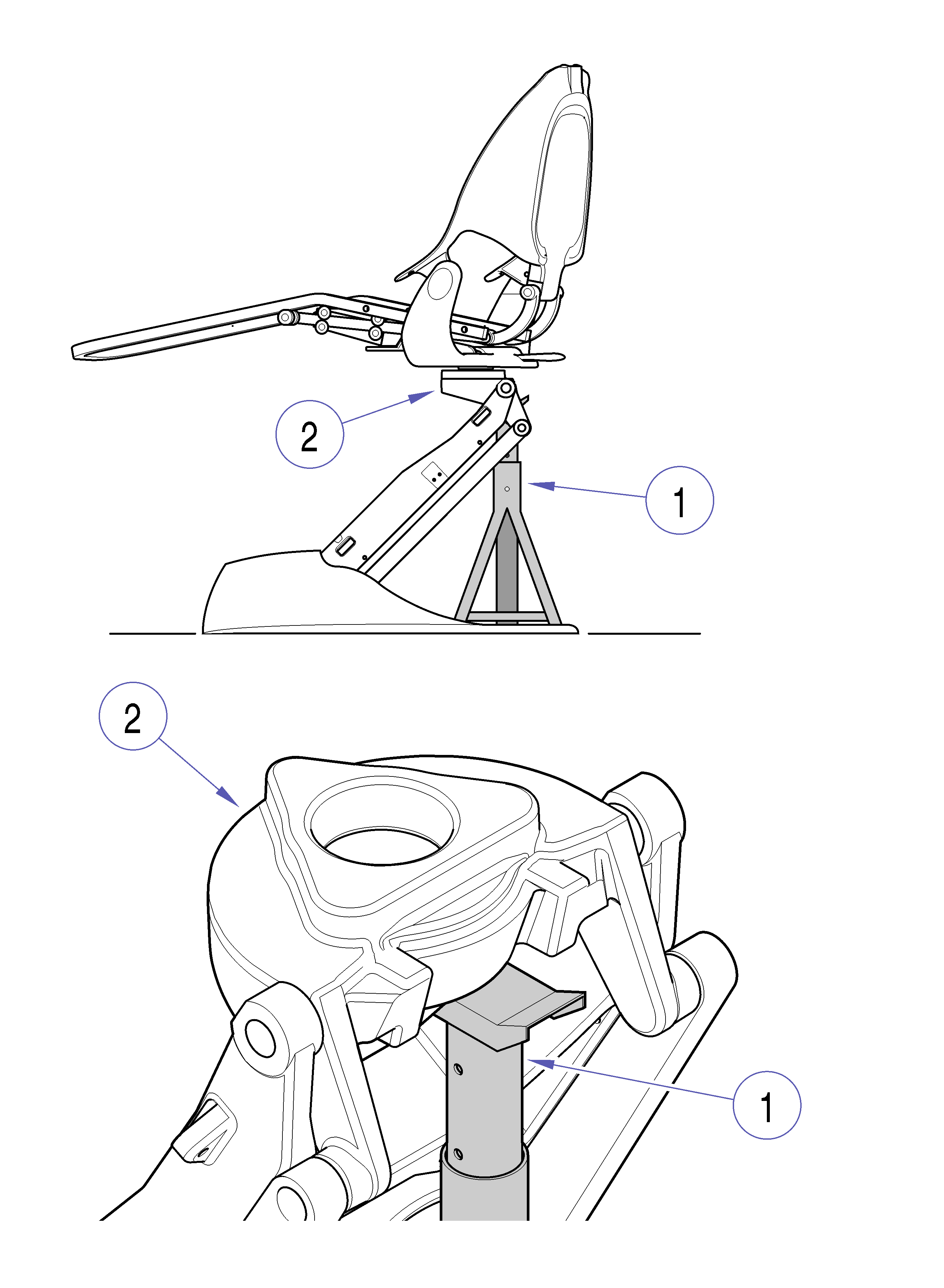
b.Place jack stands, Item 1, beneath upper lift casting, Item 2, and lower chair onto stands so no pressure or weight is on base cylinder.
Make sure chair top is securely supported before starting to remove hydraulic solenoid valve. Failure to comply could result in chair top collapsing causing serious personal injury.
Hydraulic Solenoid Valve Assembly
6.Remove pressure from an operable back cylinder:
a.Plug in chair power cord.
b.Depress the Back Down directional button on foot or membrane switch until back is all the way down.
c.Depress and hold down Program button while depressing Back Down directional button lowering back until it stops.
d.Unplug power cord.
7.Remove pressure from an inoperable back cylinder
If a solenoid coil is not operable on a solenoid valve, substitute one of the other coils on the valve assembly to operate the valve. The function button for the substituted valve must be used to operate the coil.
a.Remove solenoid valve assembly, Item 1 in Hydraulic Solenoid Valve Assembly - 2 illustration, from mounting bracket, Item 2, two screws.
b.Remove malfunctioning solenoid coil, Item 3, and substitute known good coil, Item 4.
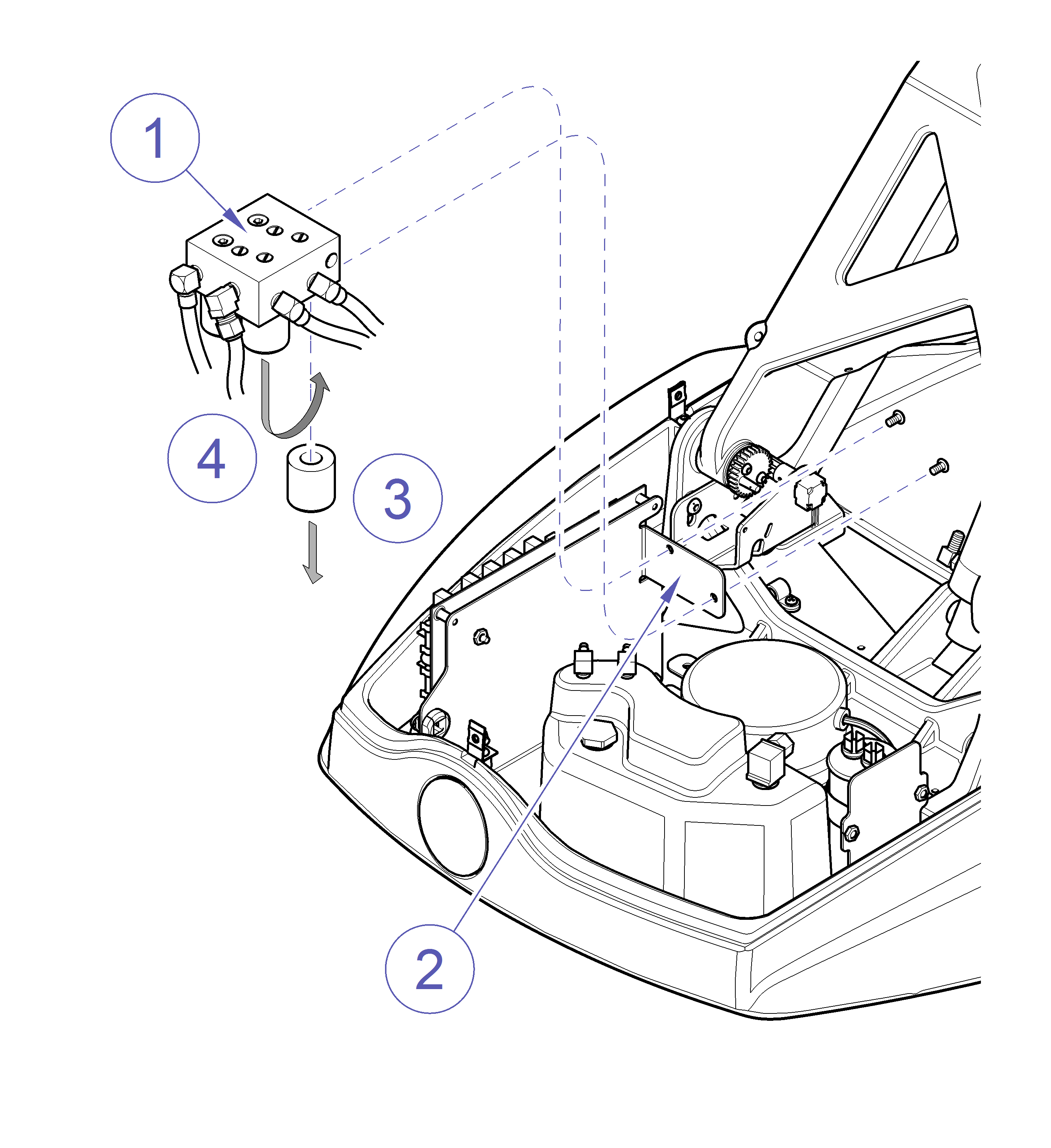
Hydraulic Solenoid Valve Assembly - 2
c.Plug power cord in and operate function button that is connected to substitute coil and place Back section in lowest position.
d.Unplug power cord.
Place absorbent towel or equivalent beneath hydraulic fittings, valves and lines before disconnecting.
8.Disconnect hydraulic lines from solenoid valve assembly, Item 1 in Hydraulic Solenoid Valve Assembly - 3 illustration.
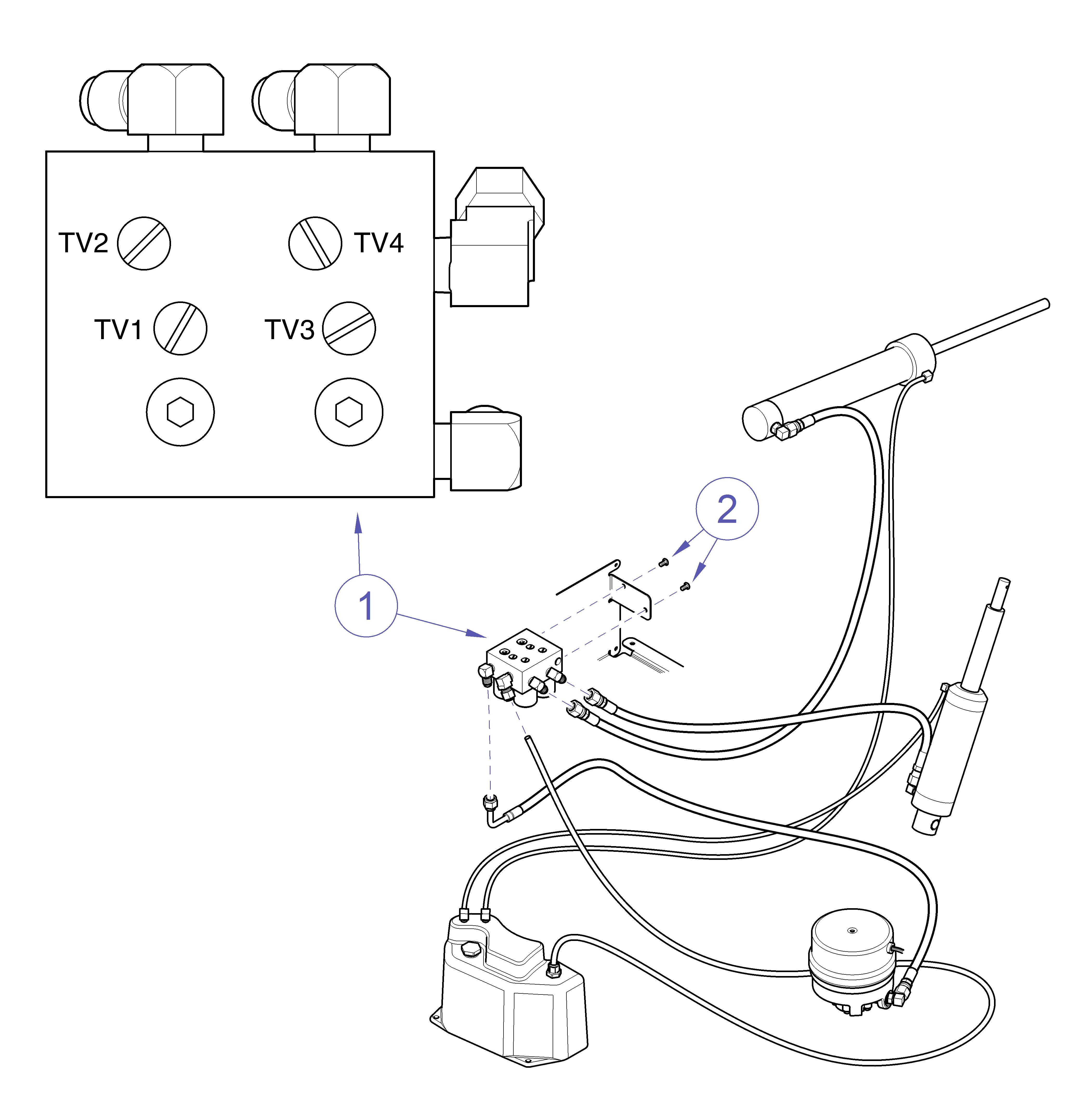
Hydraulic Solenoid Valve Assembly - 3
9.Disconnect solenoid electrical leads from J17 and J18 plug connectors on PC board. Refer to: Wiring Diagrams
10.Remove solenoid valve assembly, Item 1, from hydraulic chassis, Item 2, two screws.
1.Connect hydraulic hoses to the proper ports on the solenoid valve assembly, Item 1 in Hydraulic Solenoid Valve Assembly - 3 illustration.
2.Secure solenoid valve assembly, Item 1, to hydraulic chassis, Item 2, two screws.
The plug connectors on the replacement hydraulic valve assembly are identified with the pin connector numbers on the PC Board.
Hydraulic Solenoid Valve Assembly - 3
3.Connect the plug connectors to the appropriate pin connectors on the P.C. board. Refer to: Wiring Diagrams
Use caution to prevent electrical shock with chair plugged into outlet. Electrical components and connections are exposed.
4.Operate the chair and check for leaks.
5.Place 180 lbs. (82 kg) on chair and check rate of travel. Travel time from end-point to end-point should be 15 seconds +/- 1 second.
Use caution to prevent electrical shock with chair plugged into outlet. Electrical components and connections are exposed.
There are four Throttle Valves on the Solenoid Valve Assembly, Item 1 in Hydraulic Solenoid Valve Assembly - 3 illustration, for adjusting travel time, Base Up (TV1), Base Down (TV2), Back Up (TV3), Back Down (TV4)
Hydraulic Solenoid Valve Assembly - 3
1.With 180 lbs. (82 kg) on chair, check travel time on all four functions, Base Up, Base Down, Back Up, and Back Down.
Travel time from end-point to end-point should be 15 seconds +/- 1 second.
2.If necessary to adjust the rate of travel of a function, turn that functions Throttle Valve screw all the way in and then back it out 1/2 to 1 turn.
3.Recheck time and adjust accordingly.
Check with customer to assure the rate of travel is acceptable for them.
4.Unplug chair, install hydraulic cover, and plug chair into outlet.
