Asepsis 21® Delivery System General Description and Basic Theory of Operation
General Description
Midmark Asepsis delivery systems are available in a variety of configurations (console mounted systems, floor mounted systems, LR systems, side/rear delivery systems, cart assemblies, etc.). The delivery system components may be purchased separately or as complete chair/delivery packages.
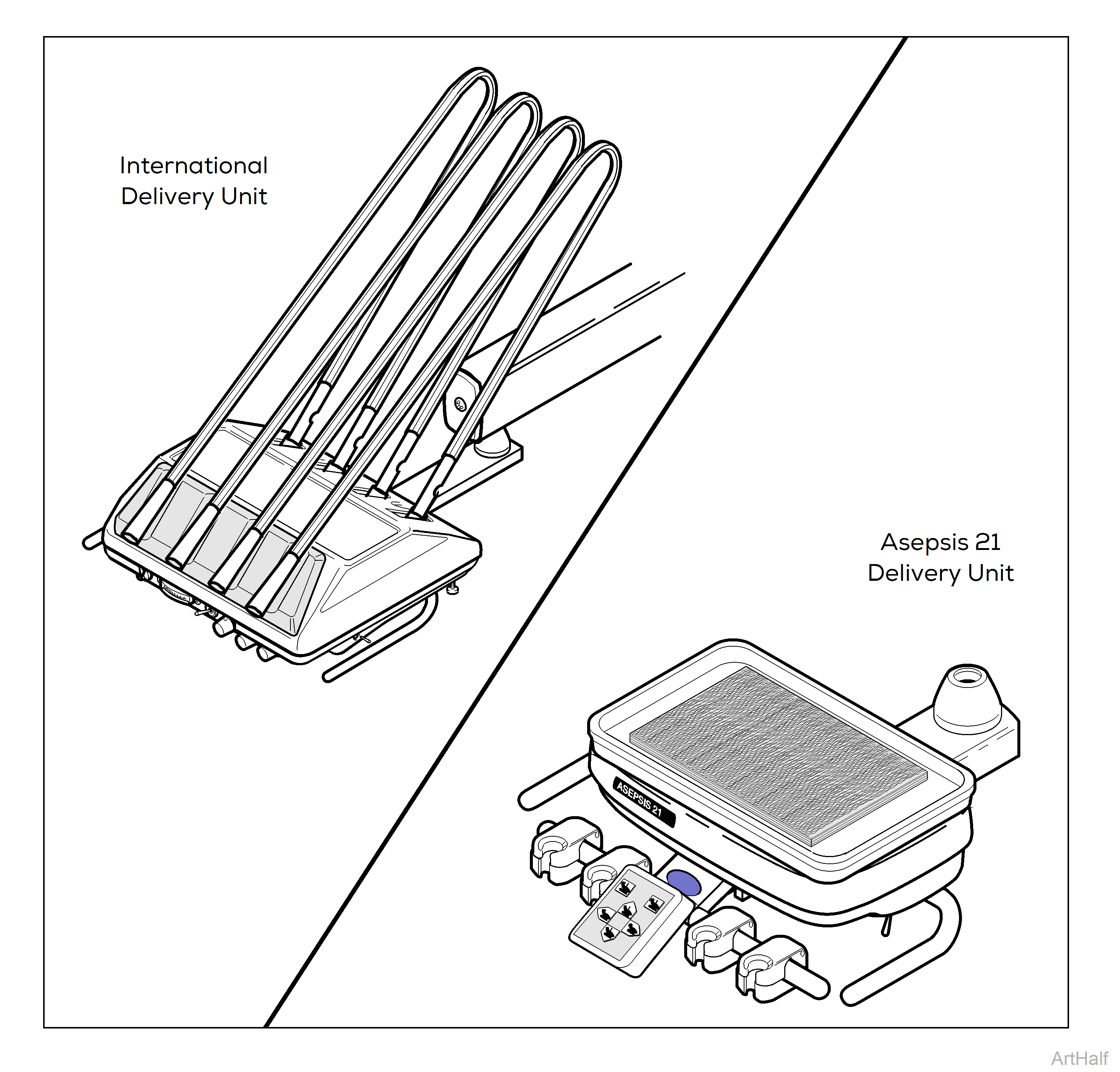
Two models of the delivery units are available: the Asepsis 21® Delivery Unit and the International (Whip) Delivery Units shown here.
Asepsis Delivery Units
Basic Theory of Operation Asepsis 21® Delivery and International (Whip) Delivery Units
When the Master ON/OFF switch is turned ON, air passes through the ON/OFF switch valve to the pilot valve block.
•If ON/OFF switch malfunctions, check purple line from pilot valve block. If air is detected, replace ON/OFF switch. If air is not detected, check pilot valve block.
The pilot valve block directs the flow of air, city water, and self contained water throughout the system.
•If air/water leaking from small holes in back of valve block, replace o-rings.
•If decreased air/water pressure from valve block is detected, check/clean valve block filters and screens.
The air and water regulators (mounted to side of valve block) adjust the air and water pressure from the block. Recommended settings: Air - 80 PSI, Water - 30 PSI.
The optional Self Contained Water System has an air regulator (mounted separately) to adjust the air pressure to the water bottle. Recommended setting: 30 PSI
•If inadequate pressure, clean and adjust regulator. Replace regulator if necessary.
Standard Foot Control (no water ON/OFF switch). This style foot control supplies drive air only to handpieces.
•If handpieces have water but no air, clean foot control. Replace foot control if necessary.
•If handpiece(s) run momentarily w/o activating foot control, disconnect drive air line and check for air pressure. If air pressure is detected, replace foot control.
Wet/Dry Foot Control (w/water ON/OFF switch). This style foot control supplies drive air and coolant water to handpieces. When the water ON/OFF switch is turned ON, the coolant water valve opens allowing coolant water to flow to handpieces.
•If no coolant water at handpiece(s), disconnect orange line from coolant water valve and activate foot control. If no air is detected, replace foot control.
•If handpiece(s) run momentarily w/o activating foot control, disconnect drive air line and check for air pressure. If air pressure is detected, replace foot control.
Asepsis 21® DeliveryUnits:
•When a handpiece is lifted out of the holder assembly, lever action opens the handpiece holder valve allowing air to flow to the kink valve assembly.
International (Whip) Delivery Units:
•When a handpiece is lifted, the whip assembly pivots causing a pilot valve to open. The open pilot valve allows air to flow to the kink valve assembly.
When the handpiece holder valve opens, air flows to the kink valve causing it to open. On the International (Whip) Delivery unit, lifting the handpiece causes the pilot valve to open and air to flow to the kink valve. Once the kink valve opens, coolant air, drive air, and coolant water all flow thru the kink valve to the handpiece.
Asepsis 21® Delivery Units:
•If kink valve does not open when handpiece is removed from holder assembly, disconnect air line coming from handpiece holder valve. If air is not detected, replace handpiece holder valve. If air is detected, replace kink valve.
International (Whip) Delivery Units:
•If kink valve does not open when handpiece is lifted, check location of the whip assembly’s wire actuator. If wire actuator is below spring hub pin, adjust screw and nut to contact stop pin at correct time.
•If kink valve does not open when handpiece is lifted (and wire actuator is in correct position), disconnect air line coming from pilot valve. If no air is detected, replace pilot valve. If air is detected, replace kink valve.
When the air lock switch (located on the right side of the delivery head) is turned ON (lock position), locking pawls (located under flex arm cover) prevent downward movement of the flex arm. The flex arm will move upward freely.
If the locking mechanism will not activate, remove flex arm cover; then perform the following steps:
1.Check that wire tie (used for shipping) around locking pawls has been removed.
2.Disconnect air line from flex arm cylinder. If air pressure is detected, replace arm lock switch valve (toggle switch on delivery head). If no air pressure is detected, replace air lock cylinder switch valve (piston style valve in flex arm).
If the locking mechanism will not release, remove the flex arm cover; then perform the following steps:
1.Tighten any loose mounting hardware on locking pawls.
2.Check that brown tubing is not kinked or pinched.
If flex arm drifts up or down, adjust nut tension on spring.
