Elevance® Delivery Interface Board Test and Repair
Use care to prevent static discharge when handling PC boards.
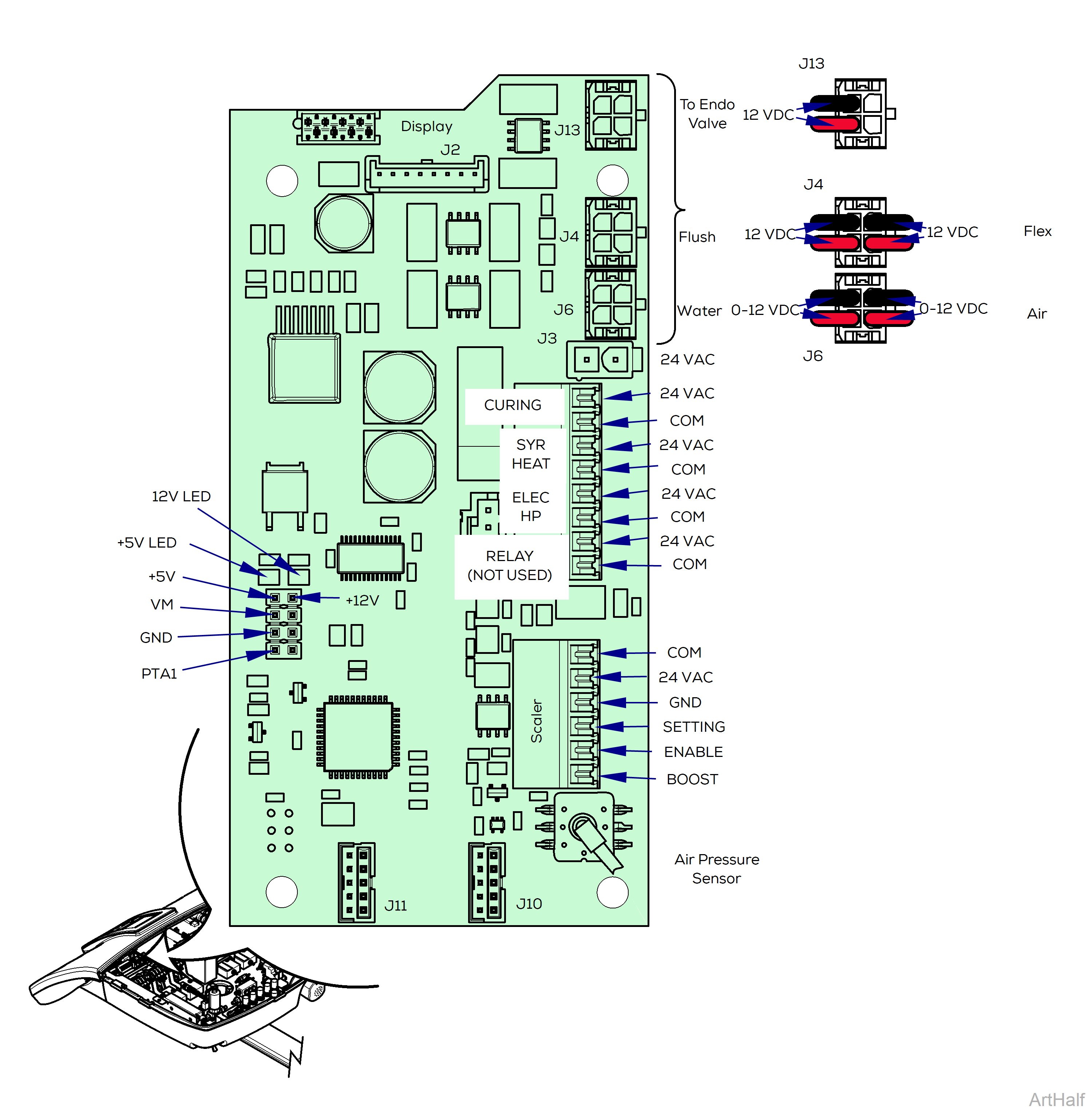
Inputs
The Air Pressure Sensor receives drive air (5 - 80 psig) when the foot pedal is pressed.
Outputs
•Electronic signals to Air and Water Proportional valves, Flex Arm Brake, Endodontics and Flush solenoids.
•Voltages to handpieces.
Use care to prevent static discharge when handling PC boards.
This method can also be used to read output voltages at the J13 and J4 connectors. These readings will either be 0 VDC when component is Off or 12 VDC when component is On.
See previous page to locate specific Interface Board outputs.
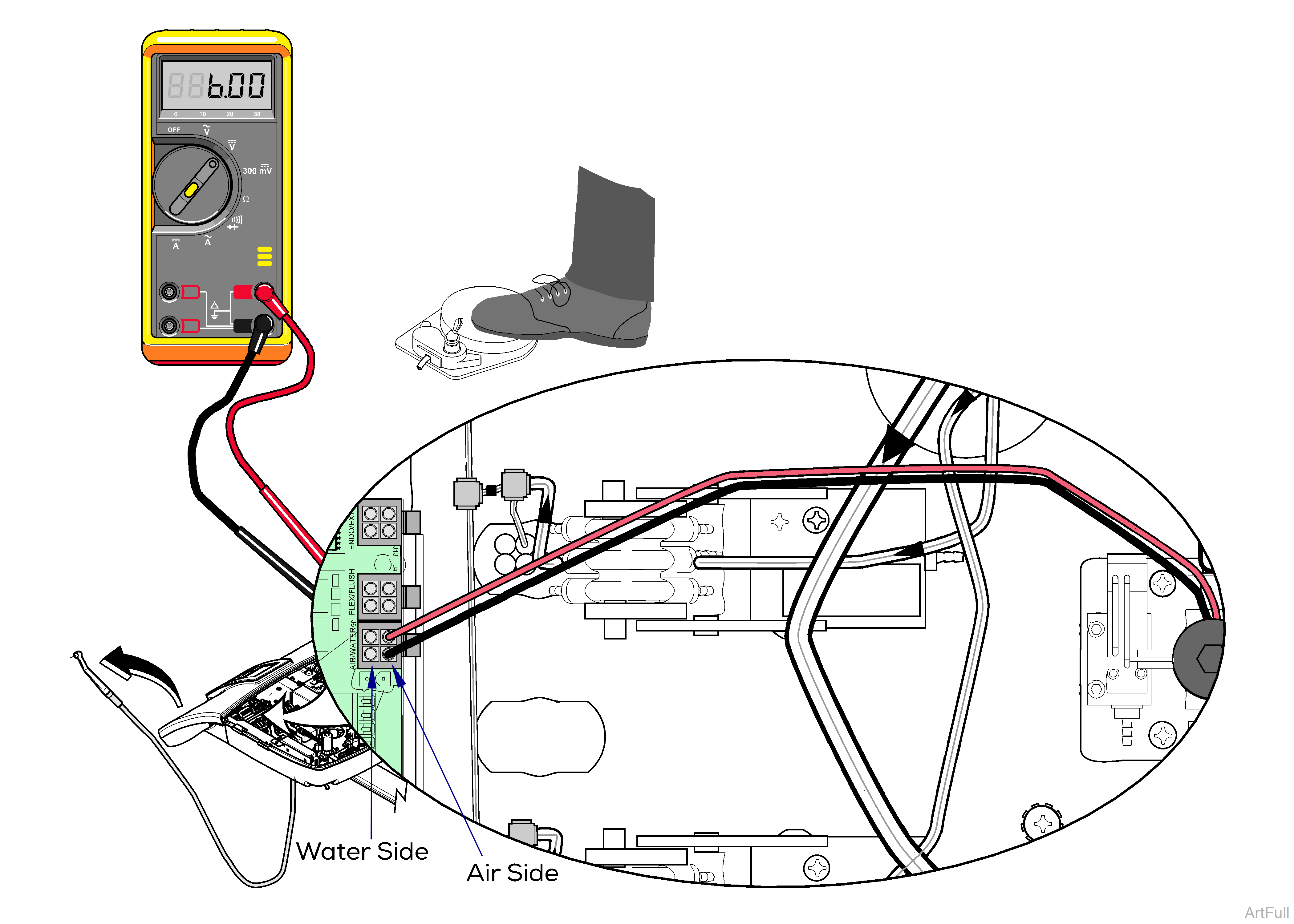
To Read the Output Voltage to the Proportional Air Valve.
1.Pull a handpiece that uses air (Bien Air, turbine, scaler, etc.).
2.Set your meter to read VDC (  ).
).
3.Insert the meter’s probes into test points shown for the Air Proportional Valve signal (J6 / Air Side on Interface Board). Probes must make contact with terminals on wires to get a valid reading.
4.Press the foot pedal full down and watch the reading on your meter. A reading between 0 and 12 volts indicates the interface board output is working properly.
The meter reading will vary dependent on the air volume setting for the pulled handpiece. If the air setting is 50% the reading will be 6.00 VDC. If the air setting is 100% the reading will be 12 VDC and so on.
This method, modified for handpieces using water, can also be used to read the output voltage to the water proportional valve, using J6/Water Side test points.
