Procenter Systems and Whip Unit Description and Theory of Operation
General Description
Midmark delivery systems are intended to provide dental professionals with air and water to operate dental handpieces, syringes, and Midmark authorized accessories during dental examinations and procedures.
Systems are available in various styles and configurations, Procenter-style Unit (console, L/R, and 12:00 casework mounted), and Whip-style Unit (console and L/R mounted).
Delivery Unit Control Locations
Basic Theory of Operation
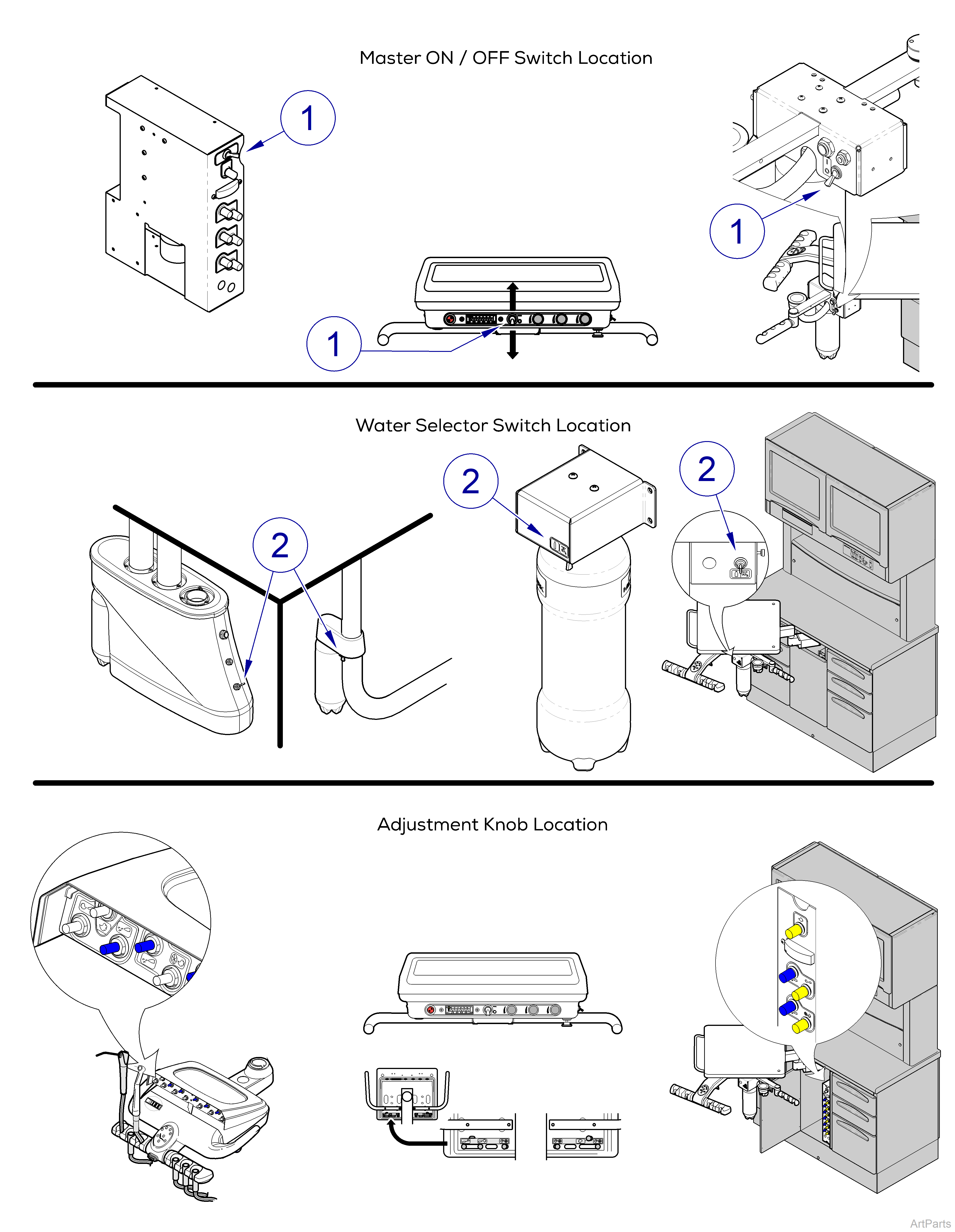
Master ON/OFF Switch - Item 1
With the air manual shut-off valve open, unregulated air is supplied to the Master ON/OFF switch on the delivery unit through 1/8 in. purple tubing. When the Master ON/OFF switch is turned ON, air passes thru the ON/OFF switch valve to the pilot air manifold through 1/8 in. red tubing. The pilot air manifold directs the flow of air to the handpiece holder valves, flex arm unlock buttons, and back to the air and water master pilot shut-off valves in the junction box through 1/8 in. red tubing.
Master Pilot Shut-Off Valves
The air from the Master ON/OFF switch opens the air and water master pilot shut-off valves allowing air/water to pass through the master pilot shut-off valves to the air/water regulators.
Air / Water Regulators
The air regulator w/ gauge provides air to the foot control throttle valve through 1/4 in. grey ribbed tubing and air to the syringe and cuspidor through 1/8 in. yellow tubing. This regulator should be set at 80 PSI to optimize performance.
The air regulator w/o gauge provides 30 PSI to pressurize the water bottle through 1/8 in. brown tubing. This regulator is preset at the factory and should not be adjusted.
An updated in-line regulator currently provides 30 PSI to the water bottle replacing above mentioned regulator.
The water regulator provides city water to the City/Bottle water selector valve through 1/8 in. blue tubing. This regulator should be set at 30 PSI to optimize performance.
Water Selector Switch Valve - Item 2
Distilled water is supplied to the selector valve from the water bottle through 1/8 in. blue tubing. City water is supplied to the selector valve from the water regulator through 1/8 in. blue tubing.
With the selector valve toggle switch in City or Bottle position, city or distilled water flows through the selector valve to the water supply manifold through 1/8 in. blue tubing. The water supply manifold directs the flow of water to the syringe adjustment valve and the handpiece adjustment valves through 1/8 in. blue tubing.
The outgoing water line from the selector valve is used for both City and Bottle water.
Foot Control Assembly
When the foot control pedal is depressed, the throttle valve in foot control opens, and supplies drive air and coolant air for the handpieces.
Drive air is supplied to the handpiece supply drive air manifold through 1/4 in. clear tubing. The handpiece supply drive air manifold directs the flow of air to the handpiece drive air adjustment valves through 1/4 in. clear tubing. The drive air is regulated by the adjustment valves then directed to the kink valves through 1/4 in. clear tubing. Coolant air is supplied to the handpiece coolant air adjustment valve through 1/8 in. green tubing. The coolant air is regulated by the adjustment valve then directed to the kink valves through 1/8 in. green tubing.
When the Wet/Dry toggle valve on foot control is switched to the Wet position, pilot air for coolant water is supplied to the kink valve manifolds through 1/8 in. orange tubing. The kink valve manifolds direct the pilot air to the coolant water adjustment valves through 1/8 in. white tubing. The pilot air opens the coolant water adjustment valves, allowing water to flow to the kink valves through 1/8 in. blue tubing.
Kink Valve Assembly
When a handpiece is removed from holder, the activation lever is released. This causes the (normally closed) handpiece holder valve to stop the airflow to the kink valve manifold through 1/8 in. purple tubing and allows the kink valve to open. When the kink valve opens, coolant air, drive air, and coolant water flow through the kink valve to the handpiece.
Adjustment Knobs - Item 3
Allow user to adjust air and water flow to instruments.
Master ON/OFF Switch - Item 1
When the Master ON/OFF switch is turned ON, air passes through the ON/OFF switch valve to the pilot valve block.
Pilot Valve Block
The pilot valve block directs the flow of air, city water, and self contained water throughout the system
Water Selector Valve - Item 2
Distilled water is supplied to the selector valve from the water bottle through 1/8 in. blue tubing. City water is supplied to the selector valve from the water regulator through 1/8 in. blue tubing.
With the selector valve toggle switch in City or Bottle position, city or distilled water flows through the selector valve to the water supply manifold through 1/8 in. blue tubing. The water supply manifold directs the flow of water to the syringe adjustment valve and the handpiece adjustment valves through 1/8 in. blue tubing.
The outgoing water line from the selector valve is used for both City and Bottle water.
Foot Control Assembly
The foot control supplies drive air and coolant water to handpieces. When the water ON/OFF switch is turned ON, the coolant water valve opens allowing coolant water to flow to handpieces.
Handpiece Operation
When a handpiece is lifted, the whip assembly pivots causing a pilot valve to close. This action shuts off the pilot air to the kink valve causing the valve to relax the tubing, allowing air flow through the kink valve tubing.
Kink Valve Assembly
When the pilot valve opens, pilot air flow shuts off to the kink valve allowing it to relax. This allows coolant air, drive air, and coolant water to flow through the kink valve tubing to the handpiece.
Adjustment Knobs - Item 3
Allow user to adjust air and water flow to instruments.
Supply Water
With the water manual shut-off valve in junction box open and the Master ON/OFF switch on delivery unit ON, the master pilot shut-off valve supplies regulated water to the cup fill flow control valve and the bowl flush control pinch valve in the cuspidor through 1/4 in. blue tubing. The cup fill flow control valve regulates the supply water, then directs the water to the cup fill water valve through 1/4 in. blue tubing. The bowl flush control pinch valve regulates the supply water, then directs the water to the bowl flush water valve through 1/4 in. blue tubing.
Supply Air
With the air manual shut-off valve in junction box open and the Master ON/OFF switch on delivery unit ON, the air regulator w/ gauge supplies 80 PSI to the two manually operated cup filler valves, cup filler primary air valve, bowl flush solenoid, and the manually operated bowl flush valve.
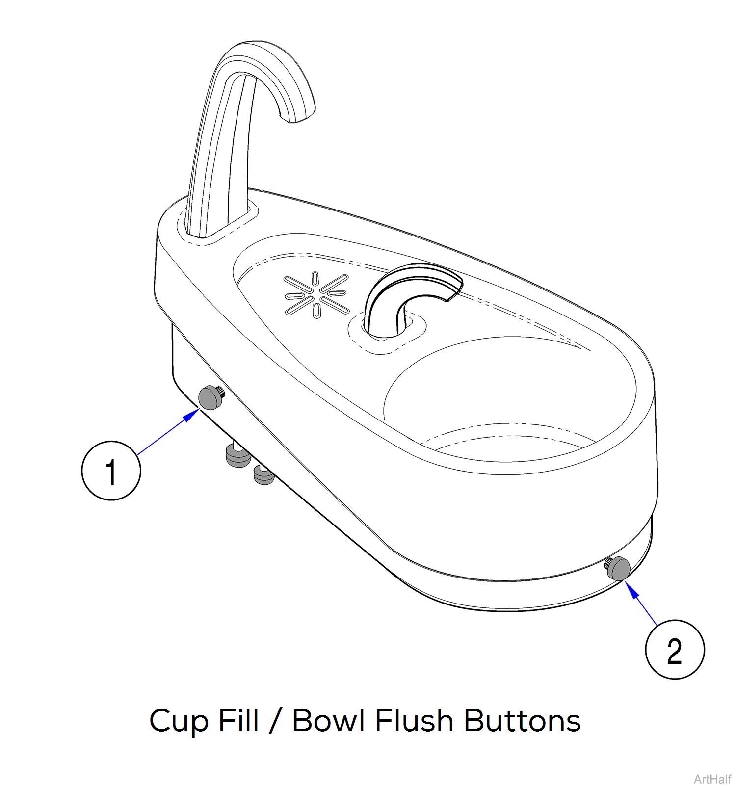
Cup Fill - Current Versions
When the manual cup fill valve button is depressed, pilot air is supplied to the shuttle valve. The shuttle valve blocks off the air line going to the opposite cup fill valve, and supplies pilot air to the cup fill water valve as well as the cup fill timing adjustment valve through 1/8” red tubing. The pilot air opens the cup fill water valve allowing water to flow to the cup fill faucet.
The cup fill timing adjustment valve gradually bleeds off air pressure from the cup fill water valve. When air pressure is removed from the cup fill water valve, the valve closes and water flow to the cup fill faucet is stopped.
The cup fill timing adjustment valve may be adjusted to shorten/lengthen the amount of time it takes to bleed off air pressure.
Cup Fill - Earlier Versions
When one of the manual cup fill valve buttons (item 1) is depressed, air is supplied to the normally open cup fill pilot air valve through 1/8 in. white tubing. Air passes through this valve to the cup fill timing adjustment valve and to the normally closed cup fill primary air valve through 1/4 in. yellow tubing.
The air opens the normally closed valve and supplies pilot air to the cup fill water valve and back to the normally open cup fill pilot air valve through 1/8 in. red tubing. The pilot air to the cup fill water valve opens the valve and allows water to flow to the cup fill faucet.
The pilot air to the normally open cup fill pilot air valve closes the valve, trapping air in the 1/4 in. yellow tubing between the pilot and primary air valves. This allows the cup fill faucet to run until air pressure in the 1/4 in yellow tubing is “bled off” thru the cup fill timing adjustment valve.
The cup fill timing adjustment valve may be adjusted to shorten/lengthen the amount of time it takes to bleed off air pressure.
Bowl Flush - Manual Push Button Operation
When the manual bowl flush valve button, Item 2, is depressed, pilot air is supplied to the bowl flush water valve as well as the bowl flush timing adjustment valve through 1/8 in. red tubing. The pilot air opens the bowl flush water valve allowing water to flow to the bowl flush faucet. The bowl flush timing adjustment valve gradually bleeds off air pressure from the bowl flush water valve. When air pressure is removed from the bowl flush water valve, the valve closes and water flow to the bowl flush faucet is stopped.
The bowl flush timing adjustment valve may be adjusted to shorten/lengthen the amount of time it takes to bleed off air pressure.
Bowl Flush - Automatic Function
When using the cuspidor with a Midmark dental chair, the operator may program a “Patient Cuspidor Position” on program button 4. This moves the chair to a desired position and electrically activates the cuspidor bowl flush solenoid.
With the chair PC board in Cuspidor Position Return Mode, pressing program button 4 begins to move the chair to the programmed position and the PC board supplies voltage to the bowl flush solenoid until chair reaches the programmed position. This voltage causes the solenoid to open, allowing pilot air to flow to the bowl flush water valve as well as the bowl flush timing adjustment valve through 1/8 in. red tubing. The pilot air opens the bowl flush water valve allowing water to flow to the bowl flush faucet. The bowl flush timing adjustment valve gradually bleeds off air pressure from the bowl flush water valve. When air pressure is removed from the bowl flush water valve, the valve closes and water flow to the bowl flush faucet is stopped.
The bowl flush timing adjustment valve may be adjusted to shorten/lengthen the amount of time it takes to bleed off air pressure.
Cuspidor Position Mode Setting for Procenter Cuspidor Mounted on Elevance Chair ONLY
Press button 4 to raise chair (patient) to the cuspidor position, a position convenient for cuspidor use. The cuspidor solenoid output also activates on the PC board. The cuspidor solenoid ouput (J5) can be connected to an optional automatic bowl flush solenoid, initiating an automatic bowl flush function as the chair raises to the cuspidor position. Press button 4 again to return chair to last position used before the cuspidor position.
1.Positon (1) on dipswitch - Position (4) on remote
2.Chair PC board sends signal to cuspidor PC board
3.Rinse solenoid turns on
4.Deposit in bowl
5.Position (4) - chair back to previous position
Only the chair back moves during this mode, the chair base does not move.
Syringe Air
With the air manual shut-off valve in junction box open and Master ON/OFF switch on delivery unit ON, the air regulator w/ gauge supplies 80 PSI to the syringe through 1/8 in. yellow tubing.
Supply Water
The City / Bottle water selector valve supplies water to the syringe and water quick connect valve through 1/8 in. blue tubing.
City/Bottle Water Selector Valve
Distilled water is supplied to the selector valve from the delivery system water bottle through 1/8 in. blue tubing. City water is supplied to the selector valve from the water regulator through 1/8 in. blue tubing.
With the selector valve toggle switch in City or Bottle position, city or distilled water flows thru the selector valve to the syringe through 1/8 in. blue tubing.
The outgoing water line from the selector valve is used for both City and Bottle water.
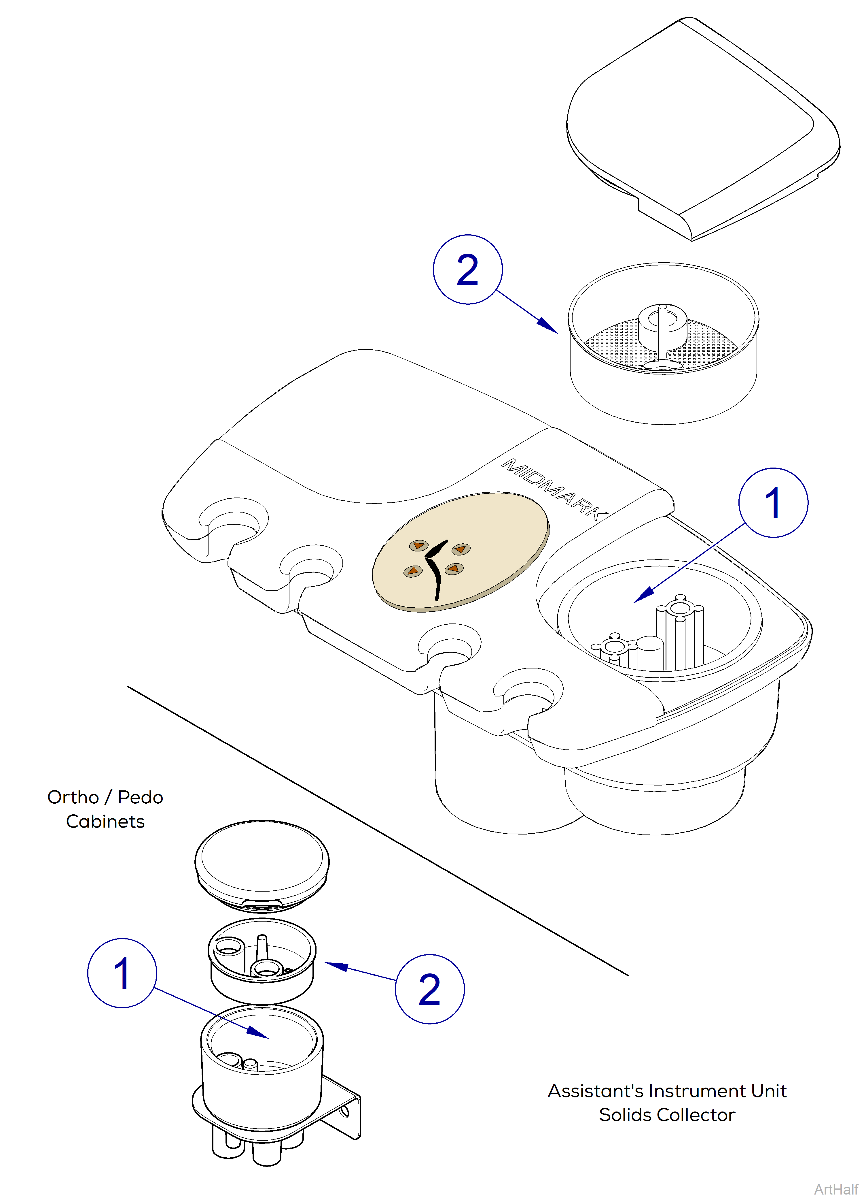
Vacuum
The central vacuum unit (not provided w/ delivery system) provides suction for the HVE and saliva ejector.
Vacuum tubing connects to the central vacuum unit in the junction box, runs through the umbilical and connects to the solids collector housing, Item 1 inside of the assistant’s unit. The HVE and saliva ejector hoses connect to the solids collector housing under the assistant’s unit.
Any unused, ejector hose connection holes under the solids collector must be capped for proper operation.
With the central vacuum unit turned on and the lever of the desired ejector opened, there is suction present at the ejector. Any solids taken in by the ejector are caught in the solids collector basket, Item 2.
