255 Light Voltage Measurements Test and Repair
Always disconnect power before removing covers. Failure to do so may result in personal injury. Refer to Adjustments / Repair Procedures.
Ensure the PC Board does not touch the metal weldment under it.
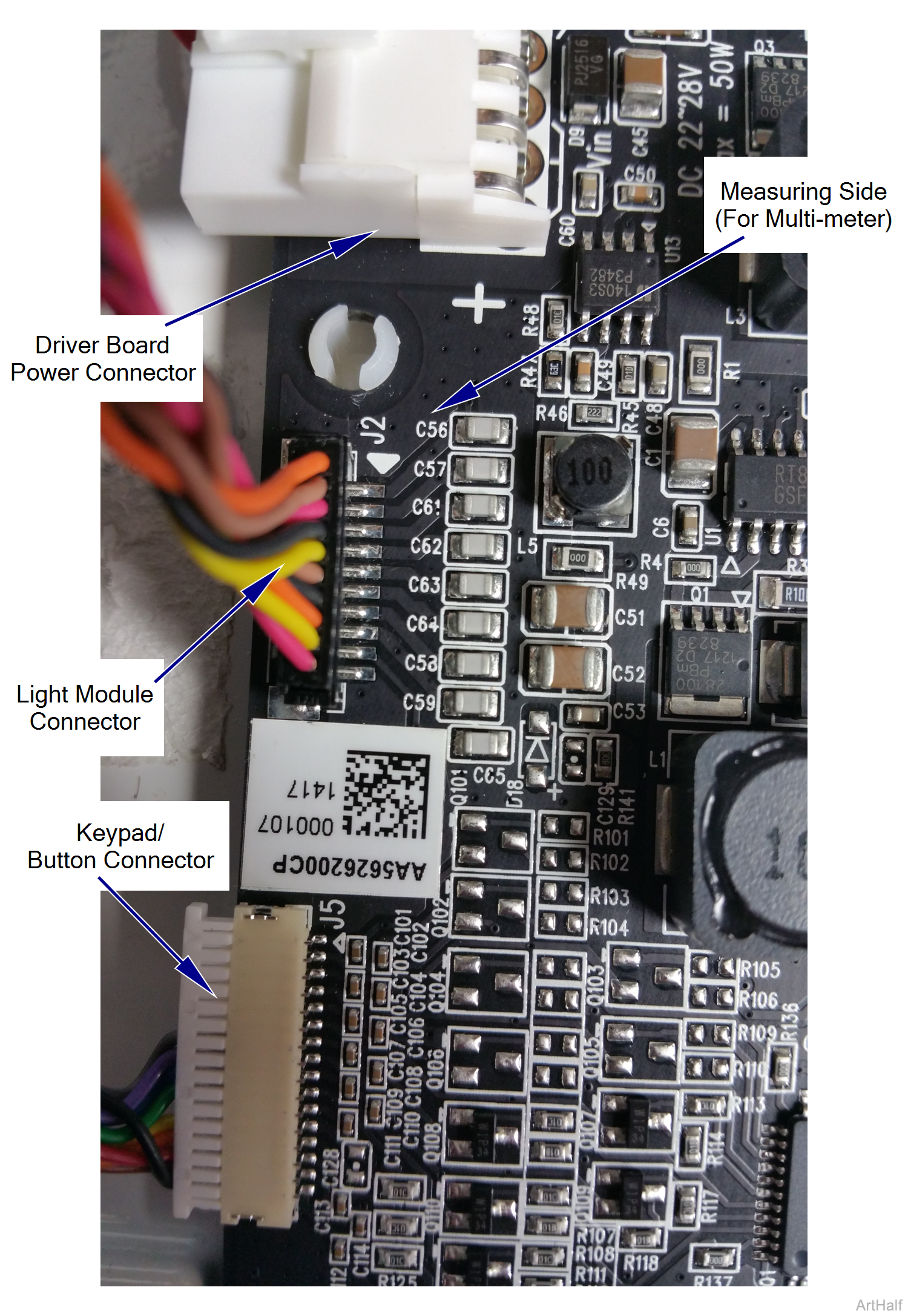
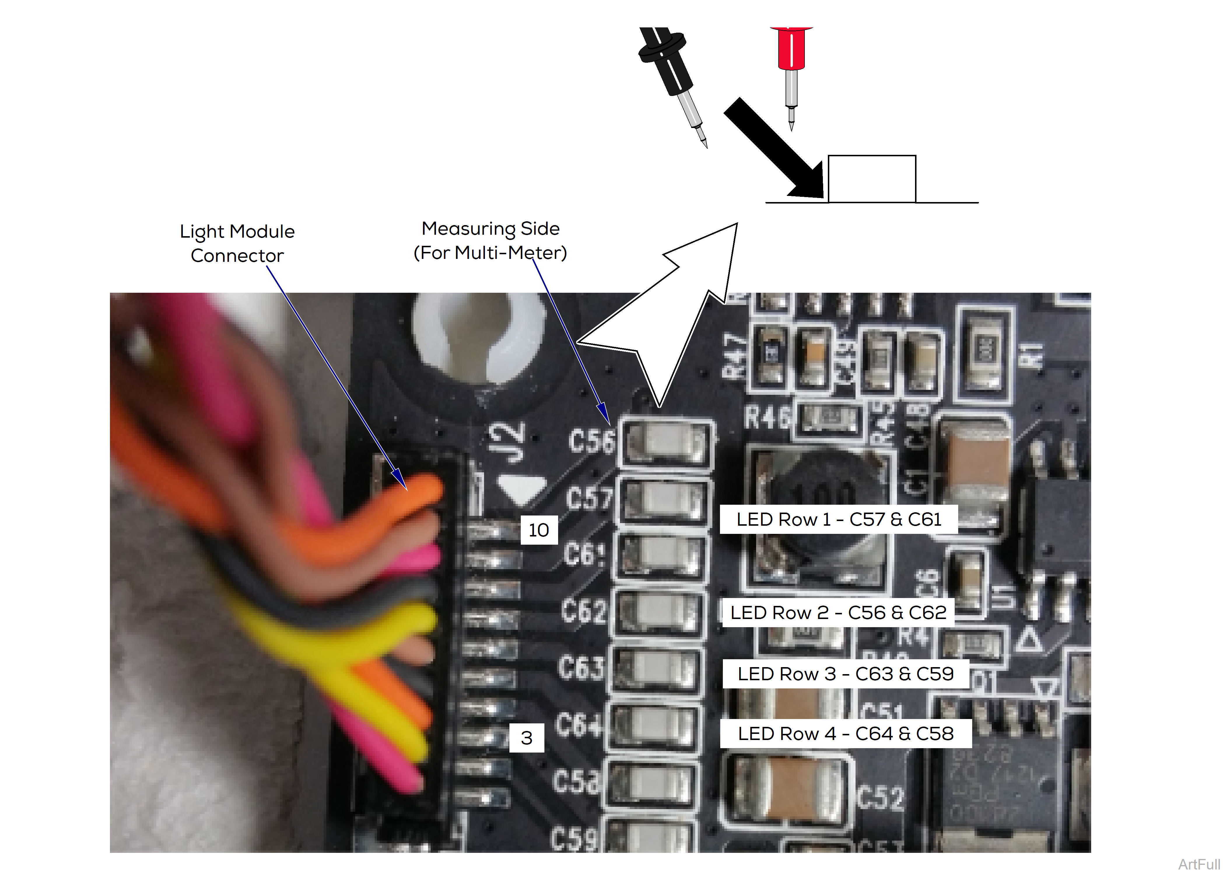
Insert multimeter probes carefully.
1.Set light at brightest setting available
2.Using multimeter, check LED lights by row on capacitors as shown.
| Pin to Capacitor | + / - | |
|---|---|---|
| 3 | C59 | - |
| 4 | C58 | - |
| 5 | C64 | + |
| 6 | C63 | + |
| 7 | C62 | + |
| 8 | C61 | + |
| 9 | C57 | - |
| 10 | C56 | - |
3.Measure voltage. Reading should be 12 VDC in each of the four rows.
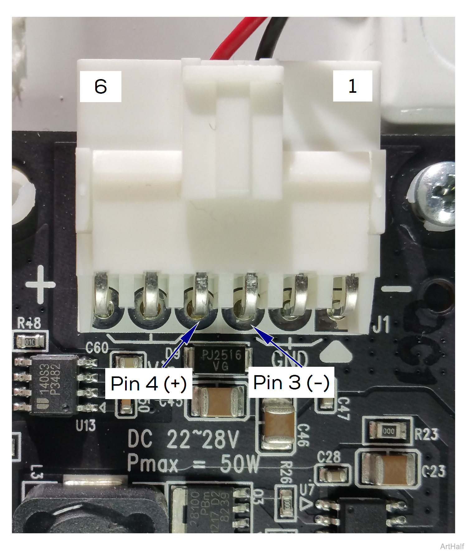
Insert multimeter probes carefully.
1.Set light at brightest setting available.
2.Using multimeter, check pin 3 (-) and pin 4 (+) on connector as shown.
3.Measure voltage. Reading should be 24 VDC.
Insert multimeter probes carefully.
1.Set light at brightest setting available.
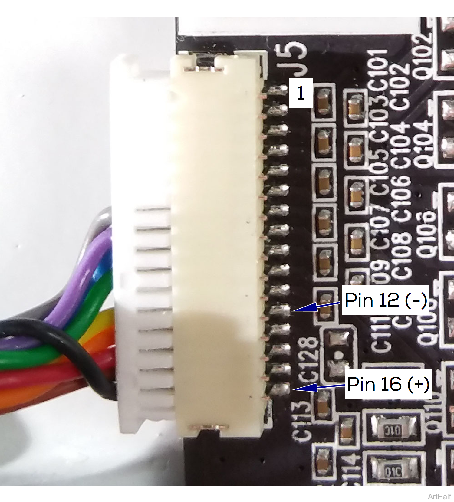
2.Using multimeter, check pin 12 (-) and pin 16 (+) on connector as shown.
3.Measure voltage. Reading should be 5 VDC.
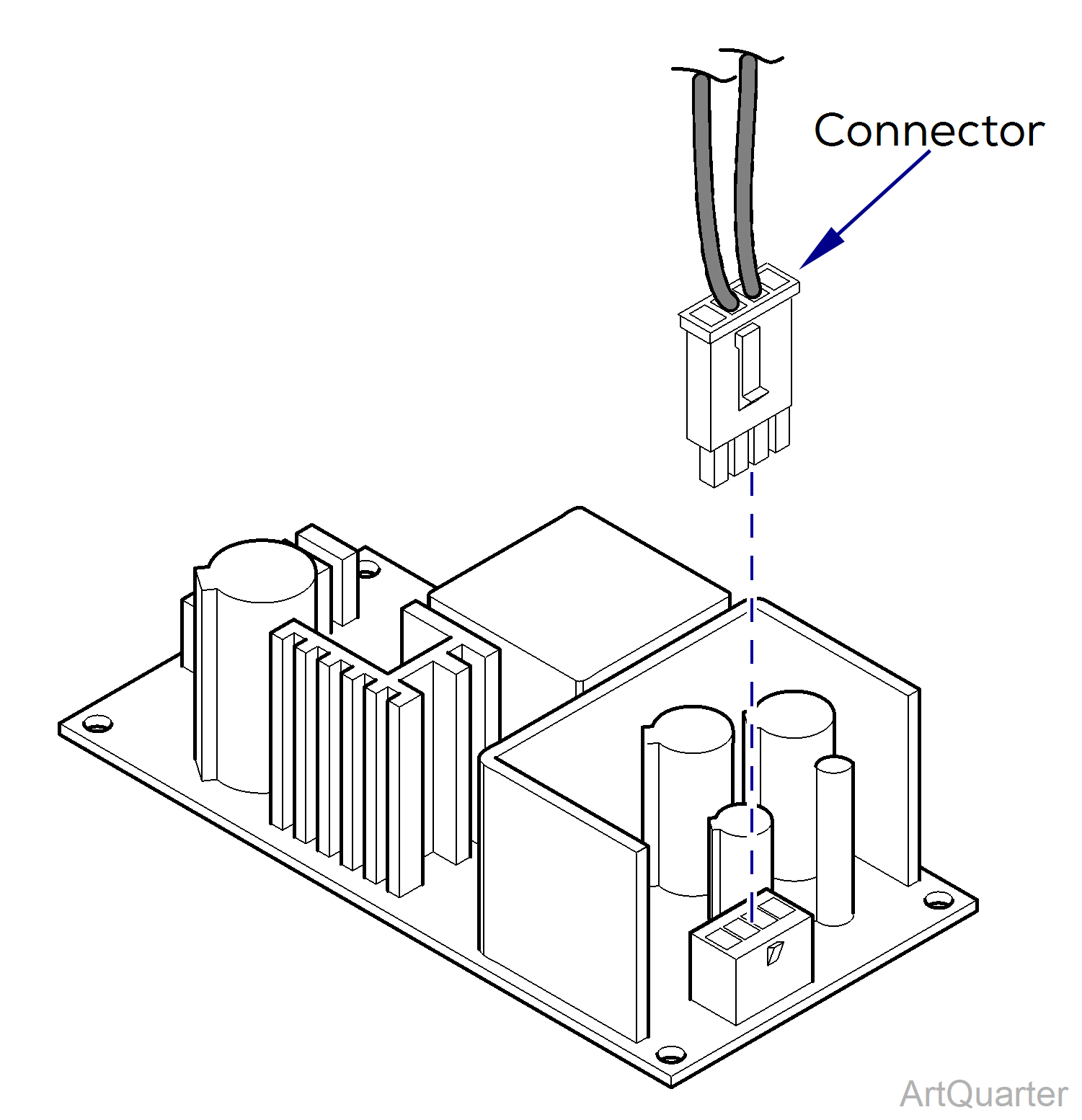
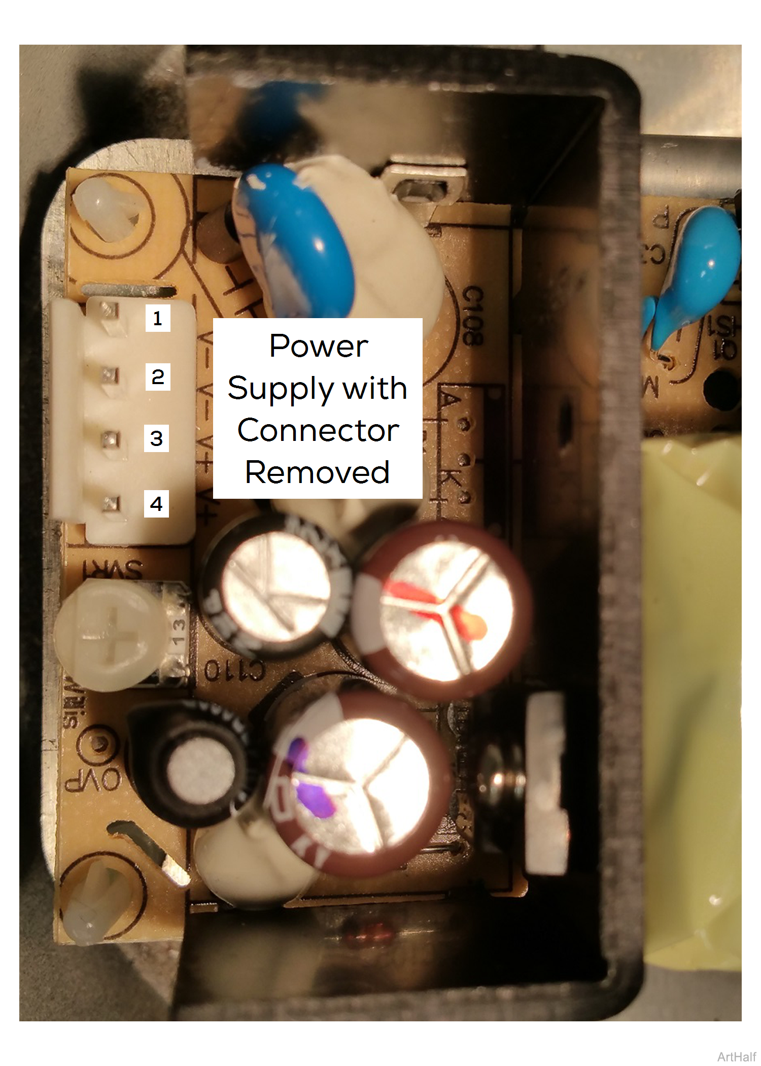
Do not touch pins or other components outside PCB protective barrier. Insert multimeter probes carefully.
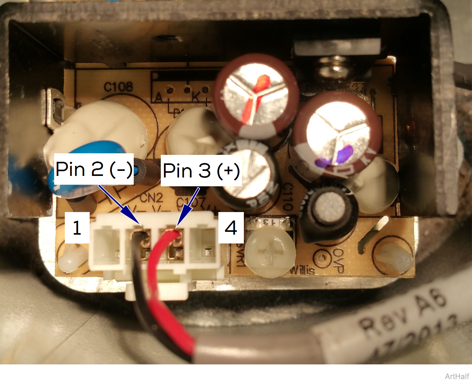
1.Remove connector as shown.
2.Measure voltage on Pin 2 (-) and Pin 3 (+) Reading should be 24 VDC.
Disconnect power to the light before performing the following procedure. Failure to comply may result in electric shock. Insert multimeter probes carefully.
Male connector is power. Connectors are small size so use small probes to measure voltage.
1.Turn light off, then disconnect power to light.
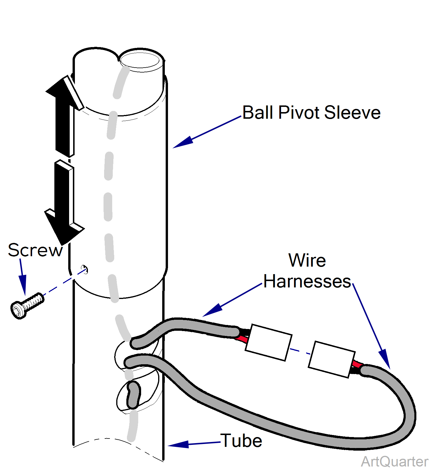
2.Remove screw, then slide pivot sleeve up.
3.Feed wire harness connectors through tube window.
4.Disconnect wire harnesses.
5.Connect power and turn light on.
6.Measure voltage with small sized multimeter. Reading should be 24 VDC.
7.Position pivot sleeve then secure with screw.
