354 Light Ceiling Mounted Wiring Diagram
|
Model |
354 -001 thru -004, -007 thru -010, -016 thru -019 (Single A) |
| Serial Number | All |
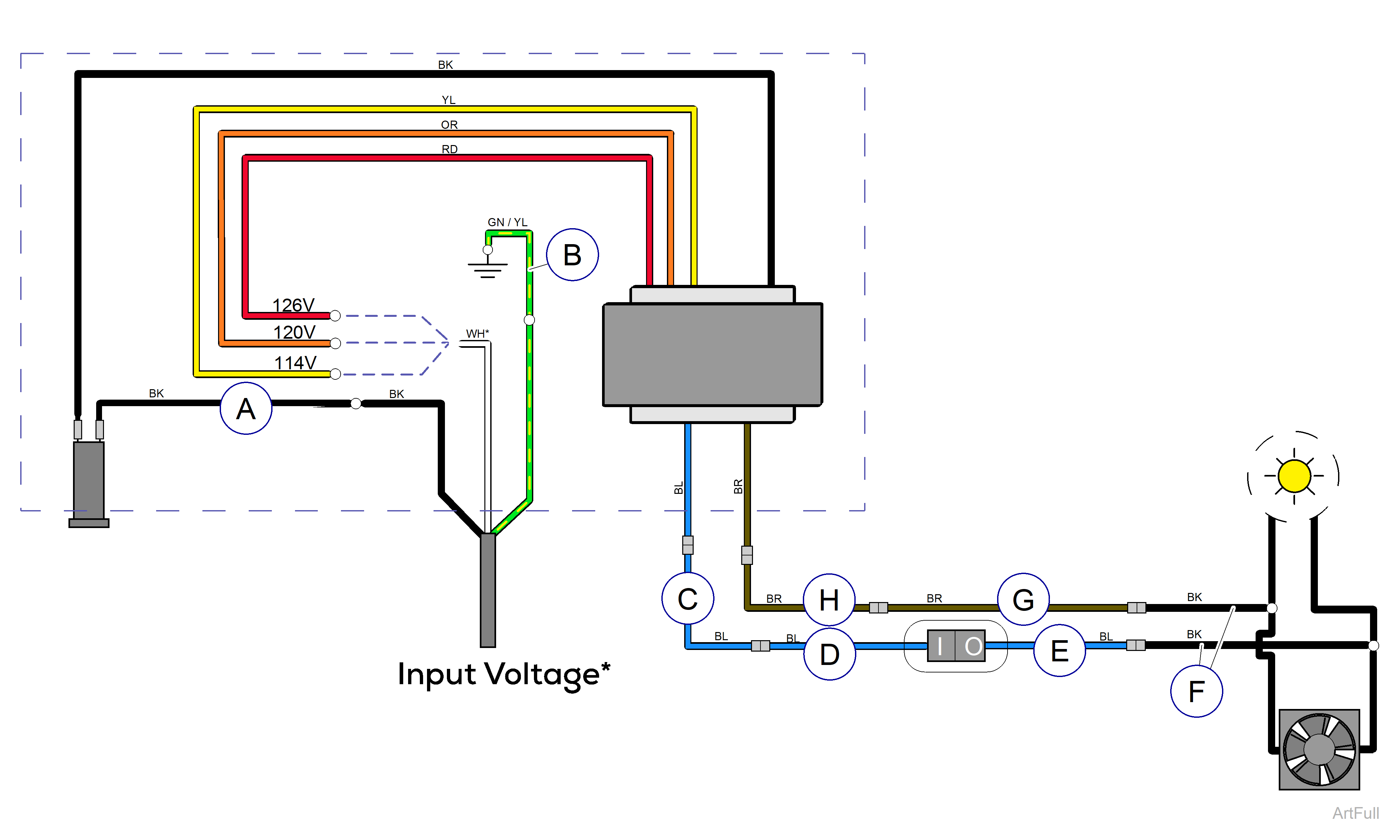
* Measure the input voltage. Connect the white wire to the proper power lead from the transformer based on the input voltage reading.
| Input Voltage | Power Lead |
|---|---|
| ≤ 117.0 VAC | Yellow |
| 117.1 to 123.0 VAC | Orange |
| ≥ 123.1 VAC | Red |
| Item | Part Number | Description |
|---|---|---|
|
A |
015-0708-07 |
Black Wire |
|
B |
015-0725-11 |
Ground Wire |
|
C |
Blue Wire Options | |
| 015-0708-18 | for 8' ceiling | |
| 015-0708-16 | for 9' ceiling | |
| 015-0708-32 | for 10' ceiling | |
|
D |
015-0708-13 | Blue Wire |
|
E |
015-0708-12 | Blue Wire |
|
F |
015-0708-22 | Black Wire |
|
G |
015-0708-14 | Brown Wire |
|
H |
Brown Wire Options | |
| 015-0708-17 | for 8' ceiling | |
| 015-0708-15 | for 9' ceiling | |
| 015-0708-31 | for 10' ceiling | |
| Color Abbreviation Chart | ||
|
NSS = Not Sold Separately | AR = As Required | NLA = No Longer Available | CFN = Call for Number Always Specify Model and Serial Number |
||
|
Model |
354 -025 / -026 / -028 / -029 (Single B) |
| Serial Number | All |
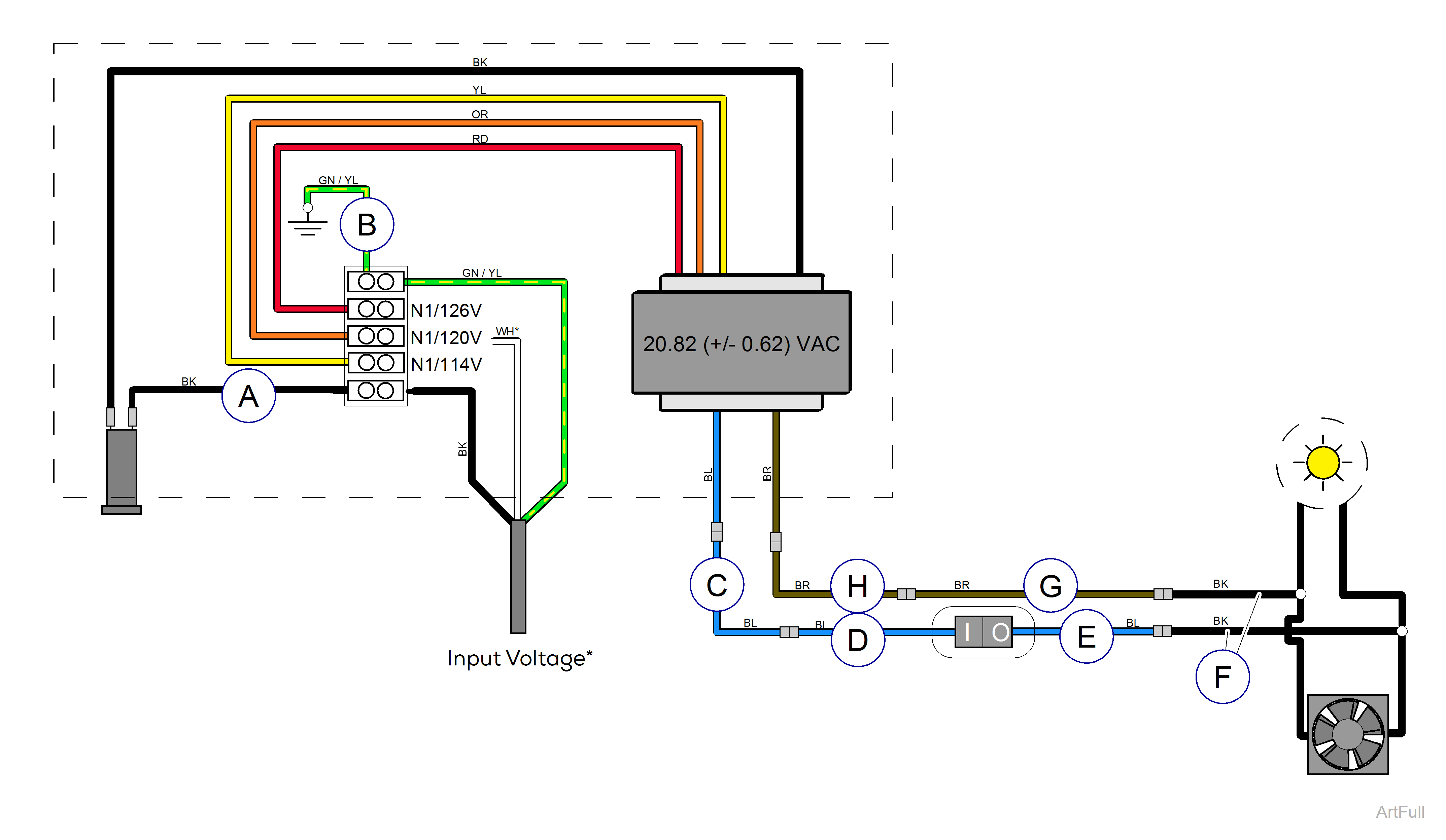
* Measure the input voltage. Connect the white wire to the proper terminal based on the input voltage reading.
| Input Voltage | Use Terminal Labeled |
|---|---|
| ≤ 117.0 VAC | N1 / 114V |
| 117.1 to 123.0 VAC | N1 / 120V |
| ≥ 123.1 VAC | N1 / 126V |
| Item | Part Number | Description |
|---|---|---|
|
A |
015-1170-02 | Black Wire |
|
B |
015-1170-04 | Ground Wire |
|
C |
Blue Wire Options | |
| 015-0708-18 | for 8' ceiling | |
| 015-0708-16 | for 9' ceiling | |
| 015-0708-32 | for 10' ceiling | |
|
D |
015-0708-13 | Blue Wire |
|
E |
015-0708-12 | Blue Wire |
|
F |
015-0708-22 | Black Wire |
|
G |
015-0708-14 | Brown Wire |
|
H |
Brown Wire Options | |
| 015-0708-17 | for 8' ceiling | |
| 015-0708-15 | for 9' ceiling | |
| 015-0708-31 | for 10' ceiling | |
| Color Abbreviation Chart | ||
|
NSS = Not Sold Separately | AR = As Required | NLA = No Longer Available | CFN = Call for Number Always Specify Model and Serial Number |
||
|
Model |
354 -031 / -032 / -034 / -035 (Double) |
| Serial Number | All |

* Measure the input voltage. Connect the white wire to the proper power lead from the transformer based on the input voltage reading.
| Input Voltage | Use Terminal Labeled |
|---|---|
| ≤ 117.0 VAC | N1 / 114V or N2 / 114V** |
| 117.1 to 123.0 VAC | N1 / 120V or N2 / 120V** |
| ≥ 123.1 VAC | N1 / 126V or N2 / 126V** |
| ** White jumper wire must be connected to both N1 and N2 terminals. | |
| Item | Part Number | Description |
|---|---|---|
|
A |
015-1170-02 | Black Wire |
|
B |
015-1170-04 | Ground Wire |
|
C |
Blue Wire Options | |
| 015-0708-18 | for 8' ceiling | |
| 015-0708-16 | for 9' ceiling | |
| 015-0708-32 | for 10' ceiling | |
|
D |
015-0708-13 | Blue Wire |
|
E |
015-0708-12 | Blue Wire |
|
F |
015-0708-22 | Black Wire |
|
G |
015-0708-14 | Brown Wire |
|
H |
Brown Wire Options | |
| 015-0708-17 | for 8' ceiling | |
| 015-0708-15 | for 9' ceiling | |
| 015-0708-31 | for 10' ceiling | |
| Color Abbreviation Chart | ||
|
NSS = Not Sold Separately | AR = As Required | NLA = No Longer Available | CFN = Call for Number Always Specify Model and Serial Number |
||
