354 Light Wall Mounted Wiring Diagram
|
Model |
354 -043 |
| Serial Number | All |
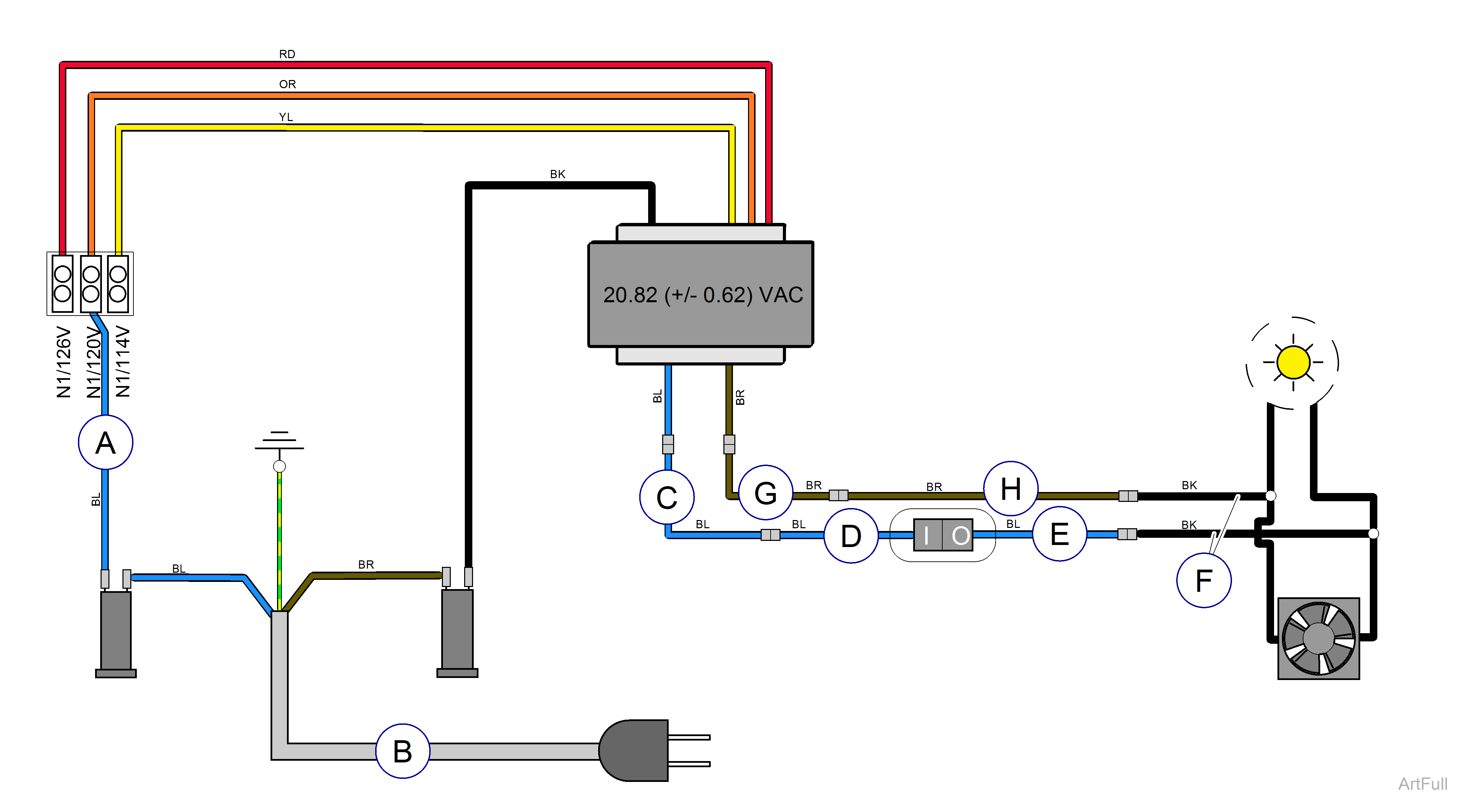
* Measure the input voltage. Connect the blue wire to the proper terminal based on the input voltage reading.
| Input Voltage | Use Terminal Labeled |
|---|---|
| ≤ 117.0 VAC | N1 / 114V |
| 117.1 to 123.0 VAC | N1 / 120V |
| ≥ 123.1 VAC | N1 / 126V |
| Item | Part Number | Description |
|---|---|---|
|
A |
015-0737-10 | Blue Wire - F2 to terminal block |
|
B |
002-1553-00 | Power Cord |
|
C |
015-0708-38 | Blue Wire |
|
D |
015-0708-13 | Blue Wire |
|
E |
015-0708-12 | Blue Wire |
|
F |
015-0708-22 | Black Wire Harness - from bulb |
|
G |
015-0708-37 | Brown Wire |
|
H |
015-0708-14 | Brown Wire |
| Color Abbreviation Chart | ||
|
NSS = Not Sold Separately | AR = As Required | NLA = No Longer Available | CFN = Call for Number Always Specify Model and Serial Number |
||
