M3 Sterilizer Input/Output (I/O) Test and Repair
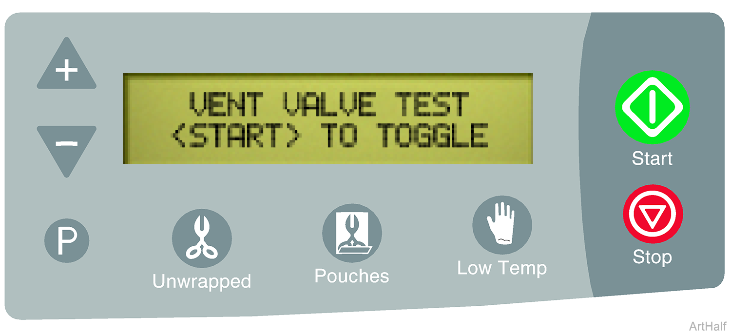
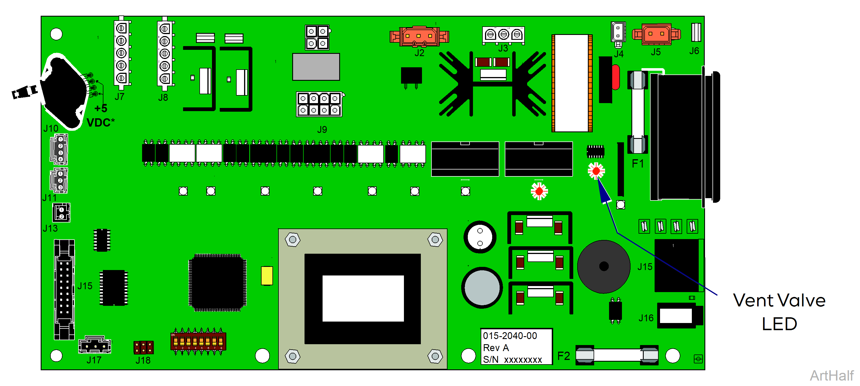
The vent valve is normally closed. When energized, the valve opens. The vent valve LED on the PC board indicates current flow to the vent valve. On: valve energized and Off: valve not energized.
1.To turn current flow to vent valve On/Off, Press the <START> button.
•When the Vent Valve LED is On the PC board is supplying current to valve.
•When the Vent Valve LED is Off there is no current to valve.
If a problem is suspected, perform the Vent Valve Voltage Test.
Press <STOP> button to advance the display to the next test.
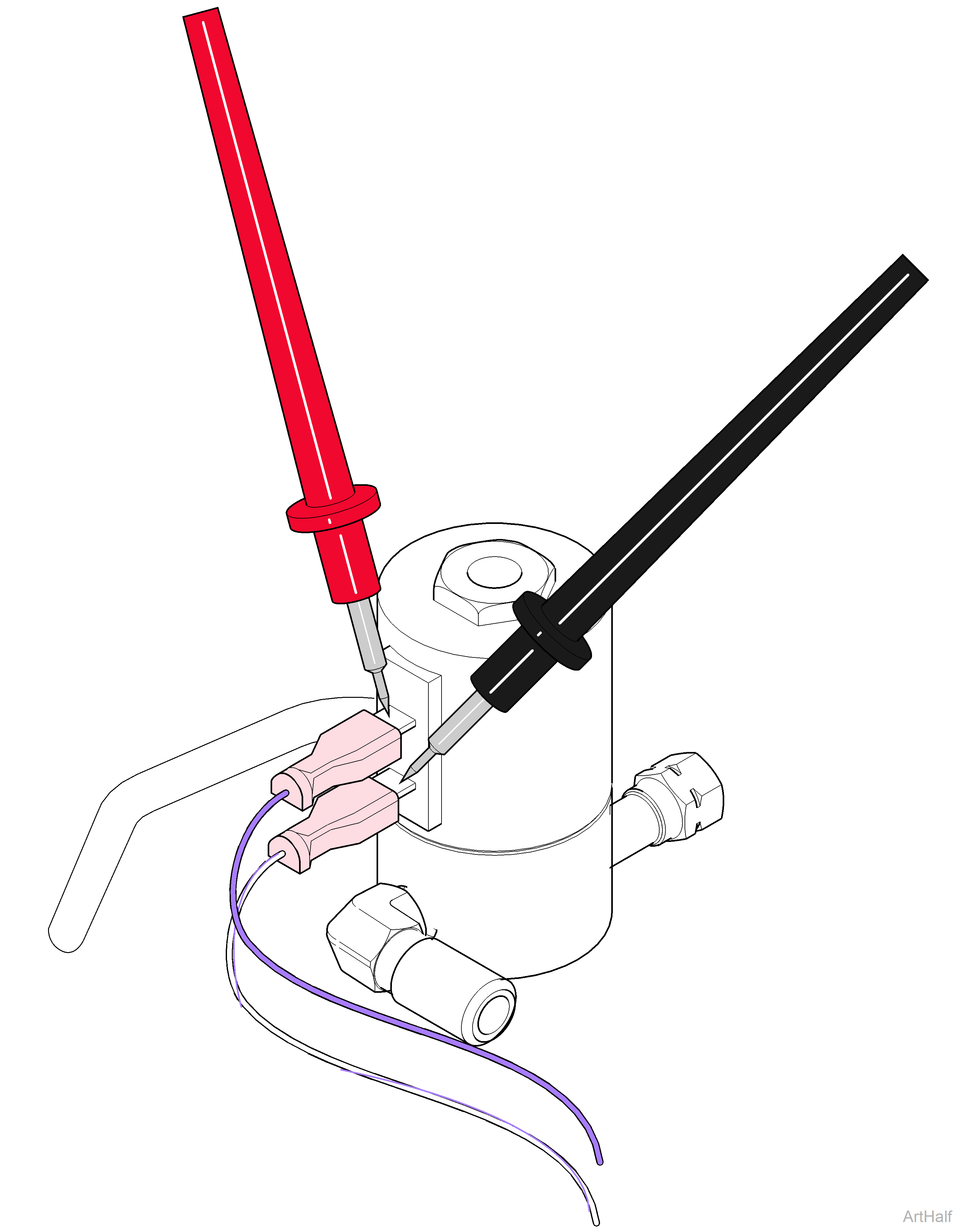
1.Press <START> button so that vent valve LED is ON.
2.Set meter to read VAC.
3.Place meter probes on vent valve terminals.
| Meter Reading | Required Action |
|---|---|
| Line voltage | PC board is OK, Perform Vent Valve Resistance Test |
| No voltage | Replace PC board |
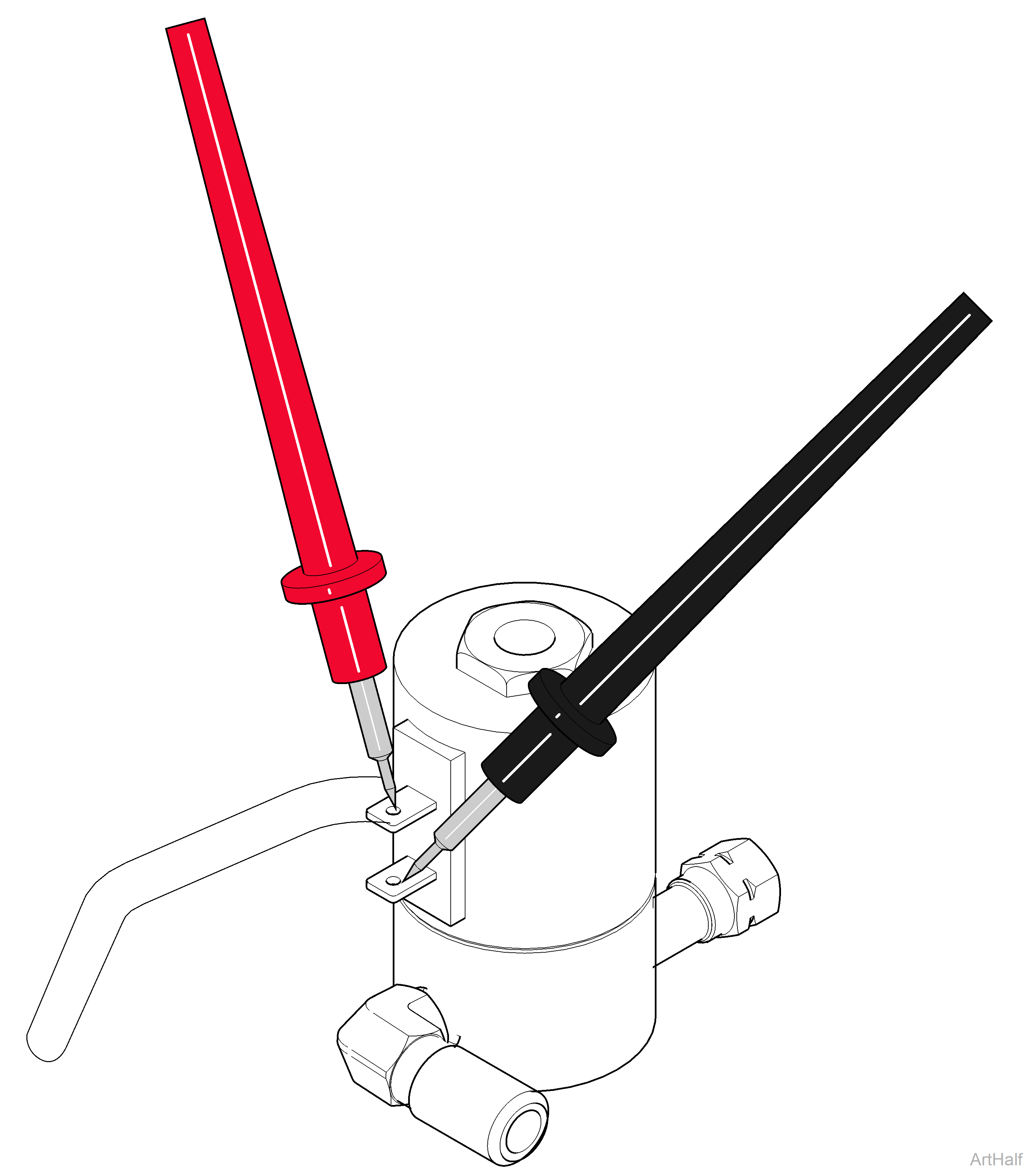
1.Tag and disconnect two wires from vent valve.
2.Set meter to read ohms Ω.
3.Place meter probes on vent valve terminals.
| Meter Reading | Required Action |
|---|---|
| Anything other than OL | Vent valve is OK |
| OL | Replace vent valve |
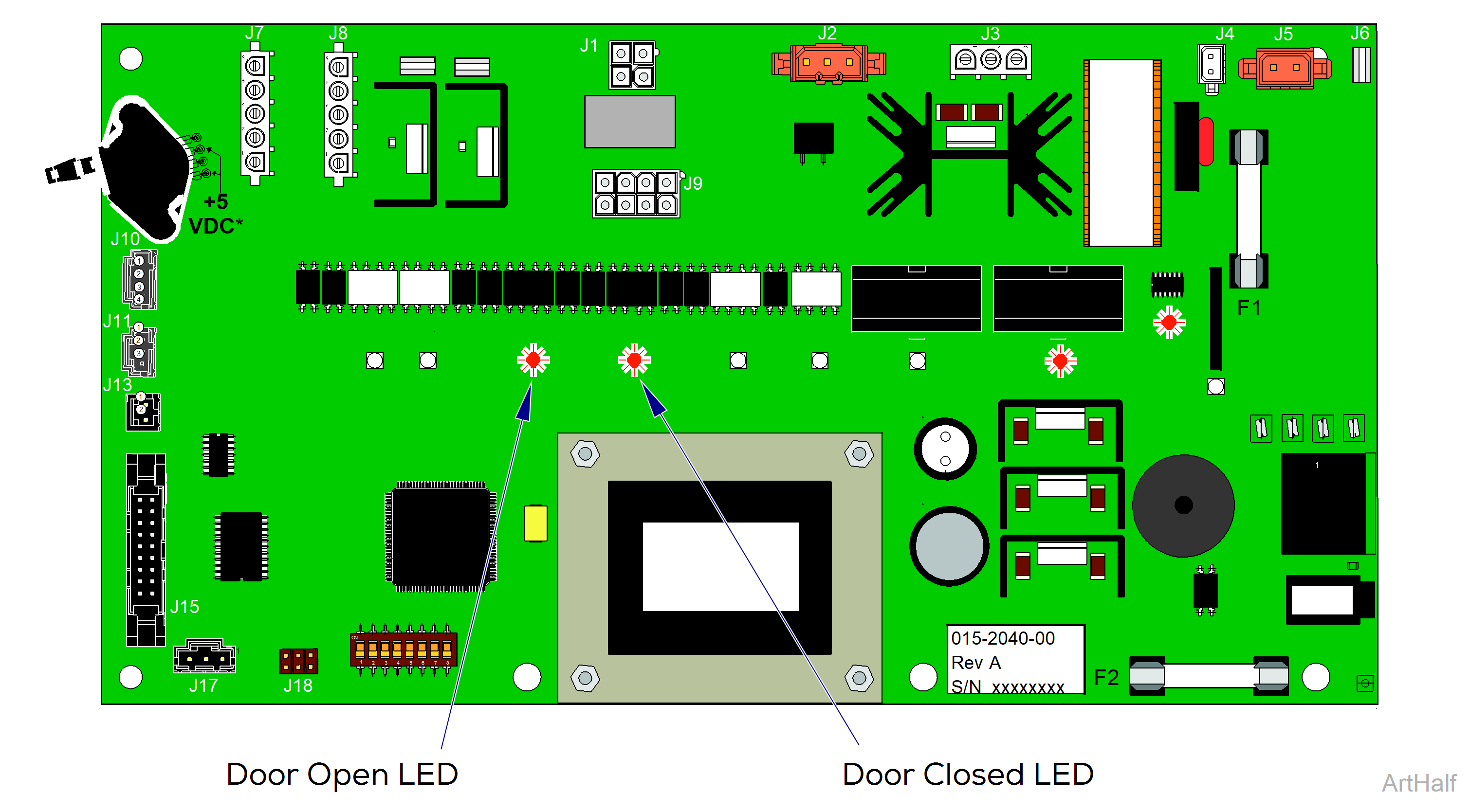
The door motor test allows you to operate the door motor without running a cycle. When energized, the door motor will run to open or closed the door depending on the starting position of the door switches.
Example: If the door open switch is tripped, the door motor will close the door when energized. If the door closed switch is tripped, the door motor will open the door when energized.
The Door Open LED on the PC board is illuminated when the door motor is opening the door. The Door Closed LED on PC board is illuminated when the door motor is closing the door.
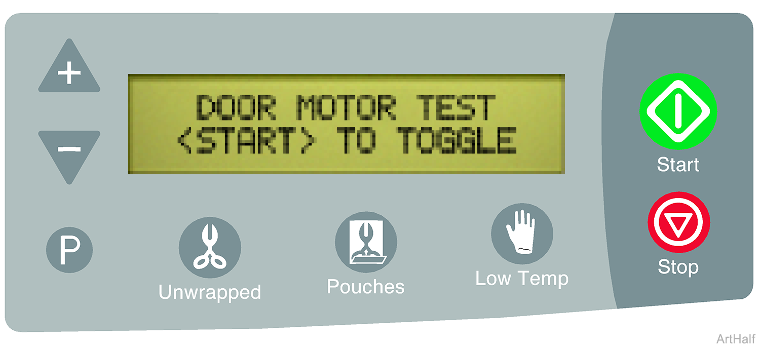
To perform this test, the door / tray assembly must be positioned so the tray switch is tripped.
1.To energize the door motor press the <START> button.
•When the Door Open or Door Closed LED light is on the PC board is supplying current to door motor.
•When LED light is off there is no current to door motor.
If a problem is suspected, perform the Door Motor Voltage Test.
Press <STOP> button to advance the display to the next test.
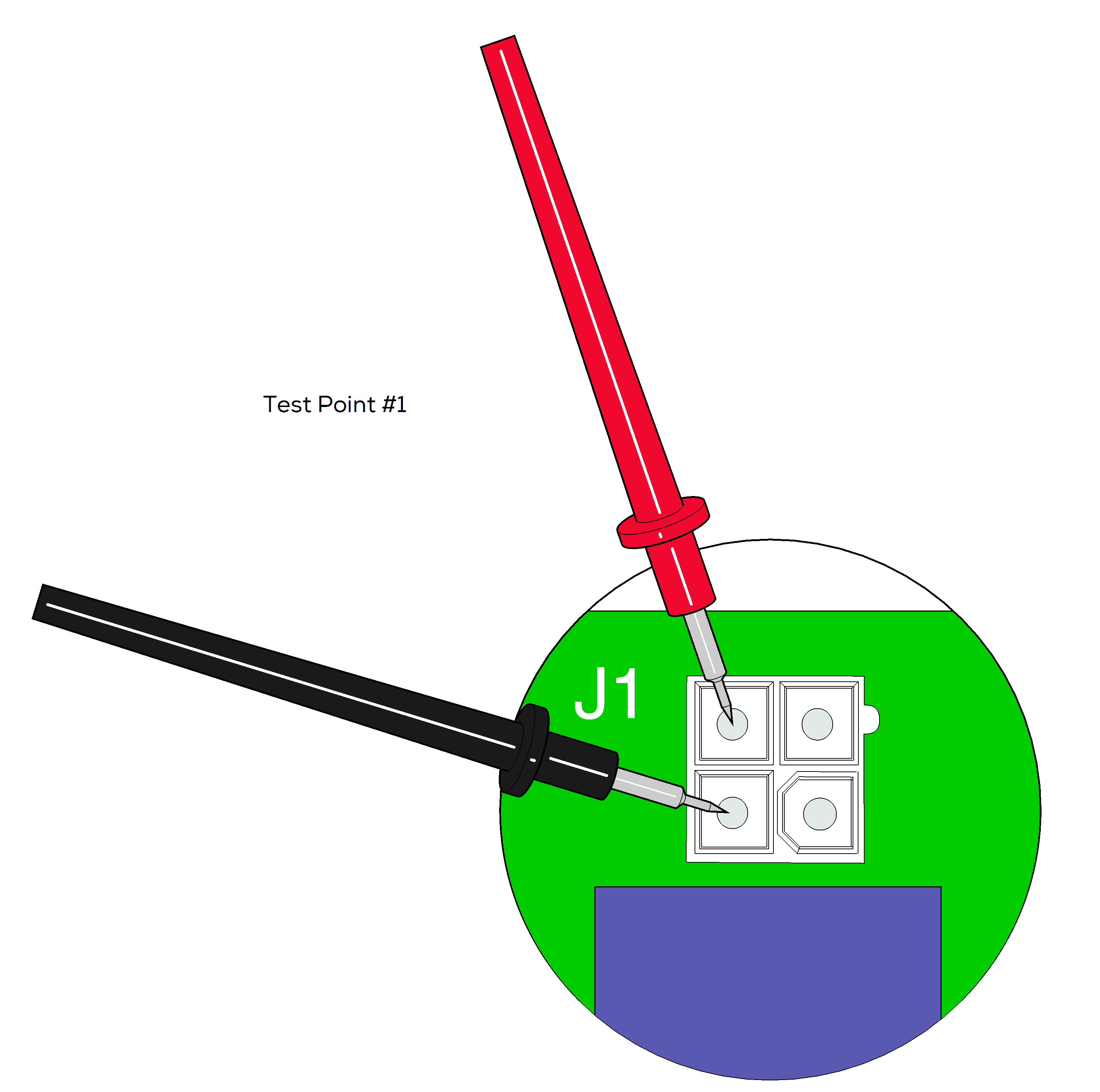
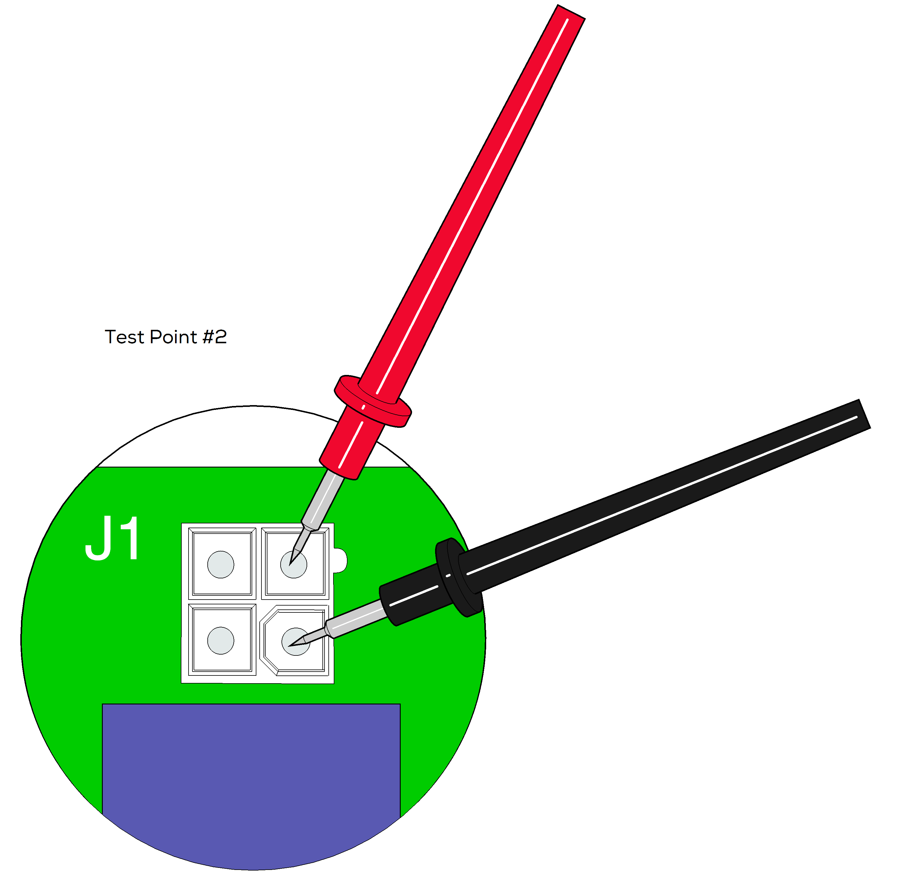
1.Disconnect door motor harness from PC board J1.
2.Press <START> button to energize the door motor.
3.Set meter to read VAC.
4.Place meter probes on test points of J1 as shown. Check voltage at both test points shown.
| Meter Reading | Required Action |
|---|---|
| Line voltage at both test points and Door Open / Closed LEDs function properly. | Perform Door Motor Resistance Test |
| No voltage at either test point and LEDs do not function. |
Be sure tray is in position, tray switch must be tripped. Check status of tray switch, door open / door closed switches. Refer to: Tray / Door Position Switch Display Screen |
| (During Door Open Test) No voltage at either test point but Door Open LED is ON. | Perform Door Motor Resistance Test |
| (During Door Closed Test) Line voltage present / Door Closed LED is ON. |
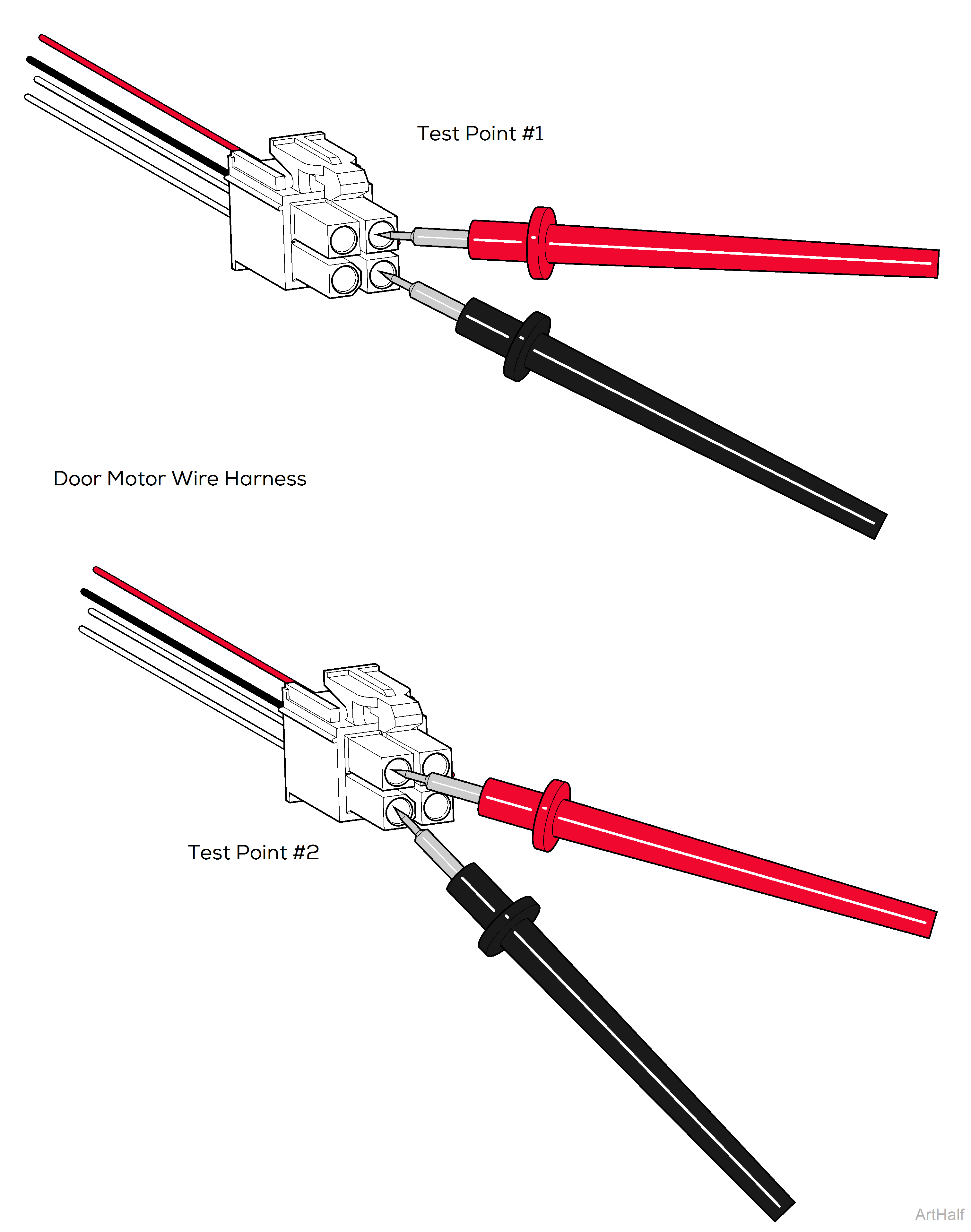
1.Disconnect door motor wire harness from PC board J1.
2.Set meter to read ohms Ω.
3.Place meter probes on wire harness pins as shown. Check resistance at both test points shown.
| Meter Reading | Required Action |
|---|---|
| 2000 to 3000 Ω | Door motor is OK |
| Out of range | Replace door motor |
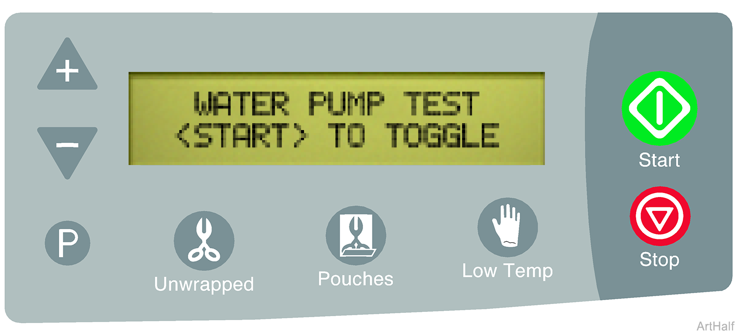
The water pump test allows you to manually energize the pump. When energized, the water pump LED illuminates, indicating current flow to the pump.
The door must be closed to perform the water pump test. If the door is open when this test is initiated, the door motor will automatically close the door before the water pump is energized. The door will open when the <STOP> button is pressed.
1.To turn current flow to water pump ON / OFF press the <START> button.
•When water pump LED is ON the PC board is supplying current to the pump.
•When water pump LED is OFF there is no current to pump.
The pump will make a buzzing sound when energized. If the water pump LED is ON, but no sound is heard, perform the Water Pump Voltage Test.


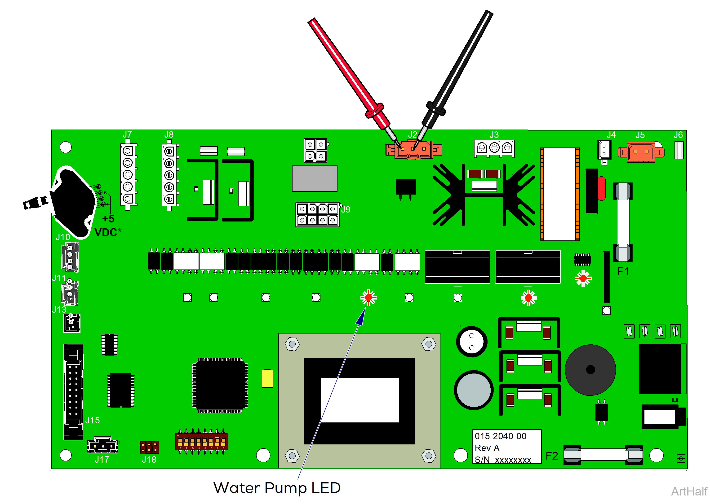
1.Disconnect water pump harness from PC board J2.
2.Press <START> button so that water pump LED is ON.
3.Set meter to read VAC.
4.Place meter probes on pin #1 and pin #2 of J2 on PC board.
| Meter Reading | Required Action |
|---|---|
| Line voltage |
PC board is OK, Perform Water Pump Resistance Test |
| No voltage | Replace PC board |
Press <STOP> button to advance the display to the next test and to stop the pump from running.
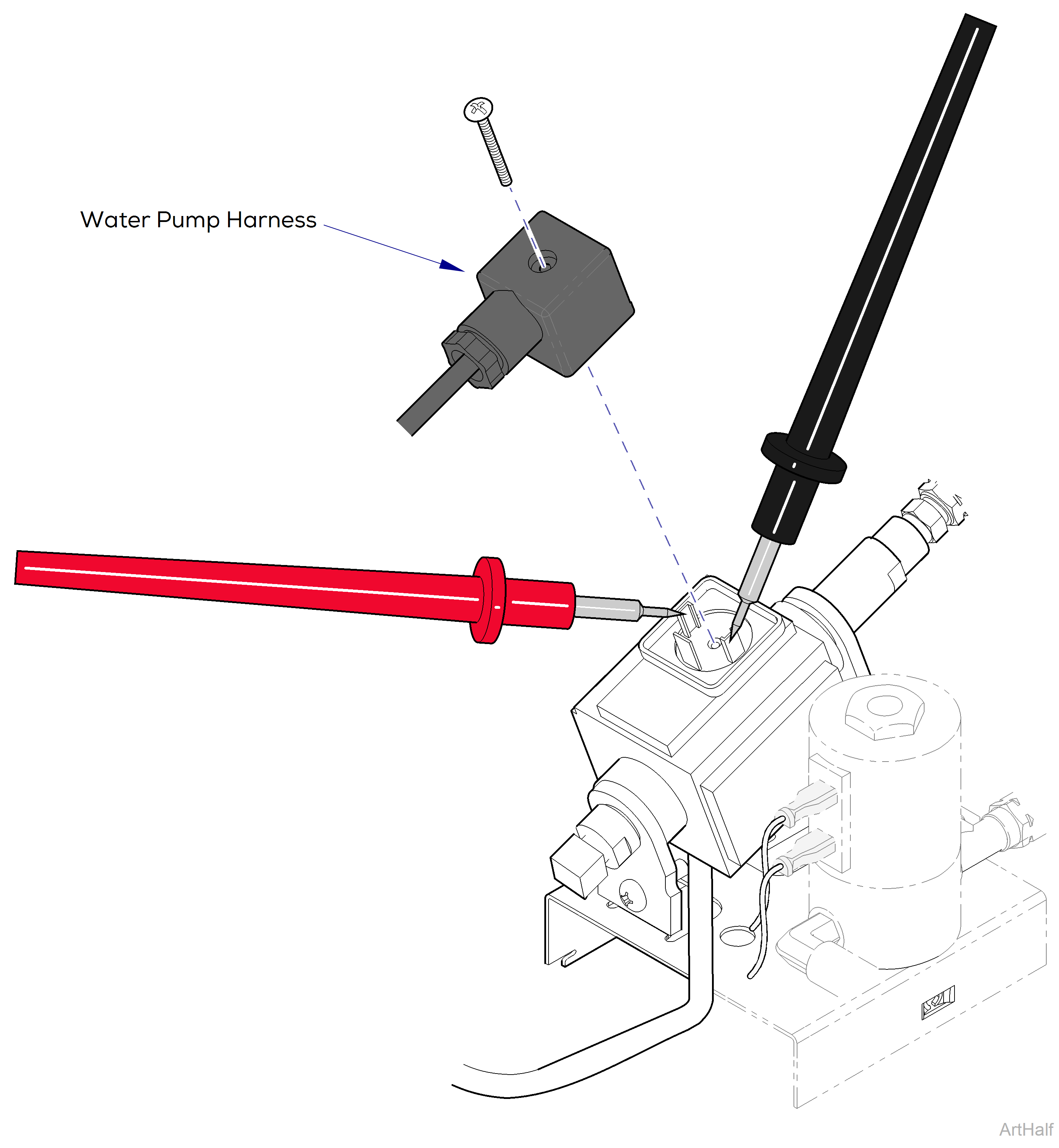
1.Remove screw, then disconnect water pump harness from pump.
2.Set meter to read ohms Ω.
3.Place meter probes on pump terminals as shown.
| Meter Reading | Required Action |
|---|---|
|
115 VAC Models: 20 to 40 Ω |
Pump is OK, replace harness |
| 230 VAC Models: 130 to 150 Ω | Pump is OK, replace harness |
| Out of range | Replace pump |

Some procedures require power to be connected with covers removed. Line voltage is present. Use extreme caution to prevent electric shock.
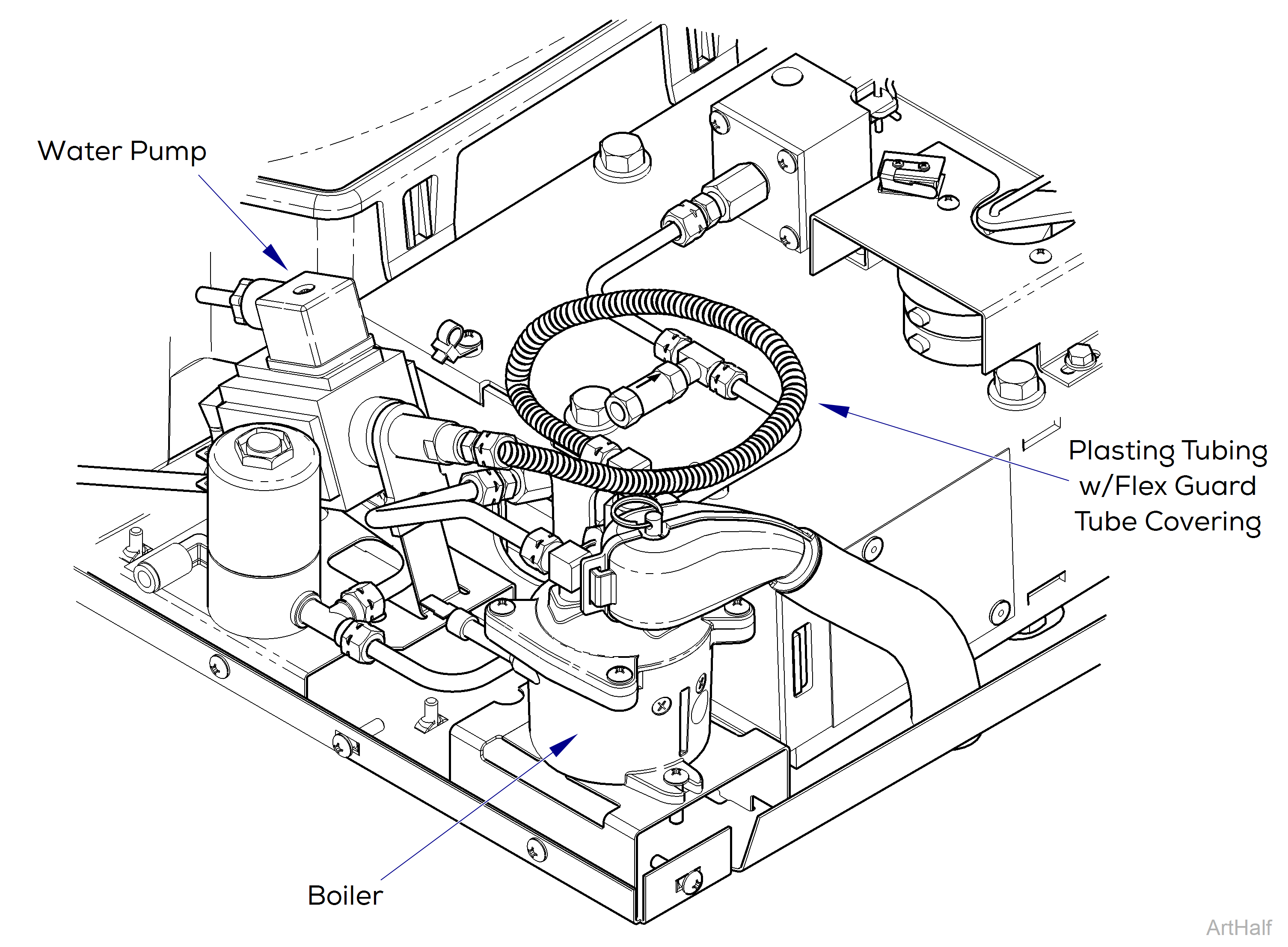
The door automatically closes before the water pump begins to run. The pump discharges approximately 3.25 ounces water every five seconds.
1.Check that the reservoir is filled with distilled water.
2.With top cover removed, go into Service Diagnostics.
3.Toggle to the Water Pump Test display screen.
4.Press <START> button once to energize and prime the water pump, until air is purged from plastic tubing connecting water pump to the boiler.
5.Press <START> again to de-energize water pump. Do not energize water pump for more then 20 seconds at a time.
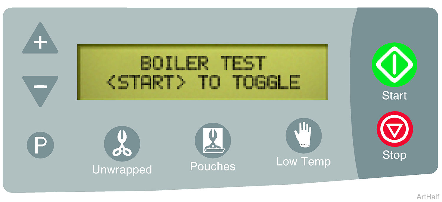
The boiler test allows you to manually energize the boiler for 15 second increments. There are two boiler LEDs that illuminate to indicate current flow to the boiler.
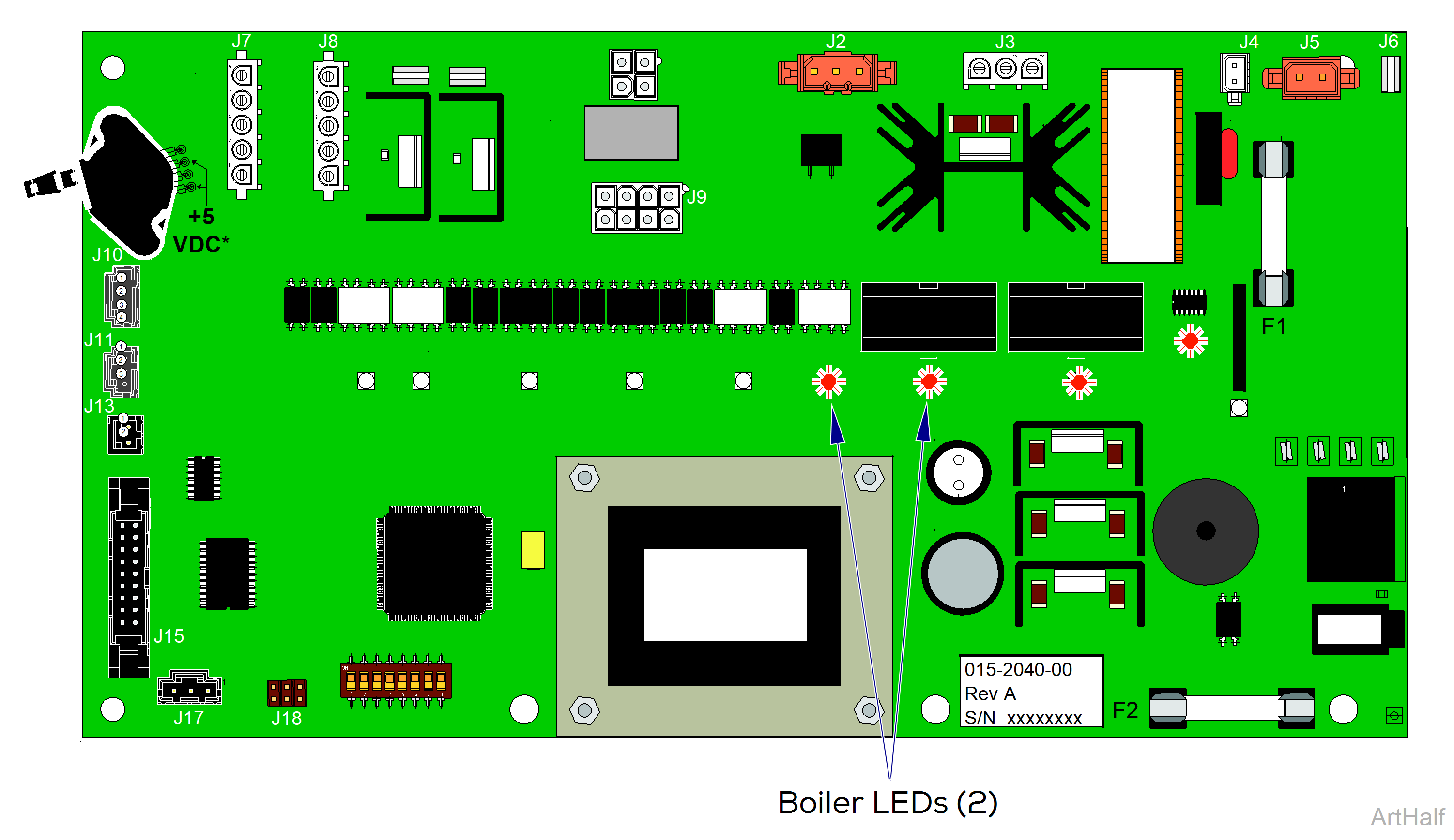
When the two boiler LEDs are On the PC board is supplying current to the boiler. When the two boiler LEDs are Off there is no current to boiler.
1.To turn current flow to boiler On / Off press the <START> button.
To verify proper operation
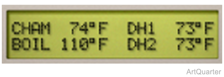
When the two boiler LEDs turn off after approx. 15 seconds, press the <STOP> button to advance to the Temperature Display Screen. The internal temperature of the boiler is shown as BOIL. If the display does not reflect an increase in temperature, perform the Boiler Voltage Test.
Press <STOP> button to advance the display to the next test.
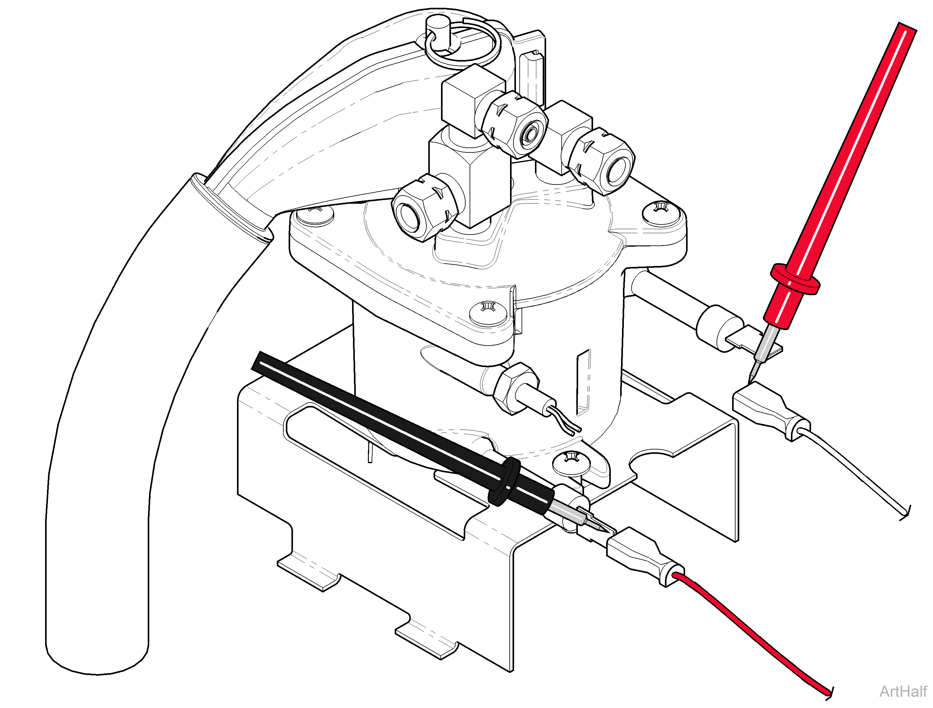
SN V1524268 thru Present Models Only: The boiler is energized continuously for the first 30 seconds of Dry Mode if the temperature is <240° F.
1.Press <START> button so that boiler LEDs are ON.
2.Set meter to read VAC.
3.Place meter probes on boiler terminals.
| Meter Reading | Required Action |
|---|---|
|
Line voltage |
PC board is OK, Perform Boiler Resistance Test |
| No voltage | Replace PC board. |
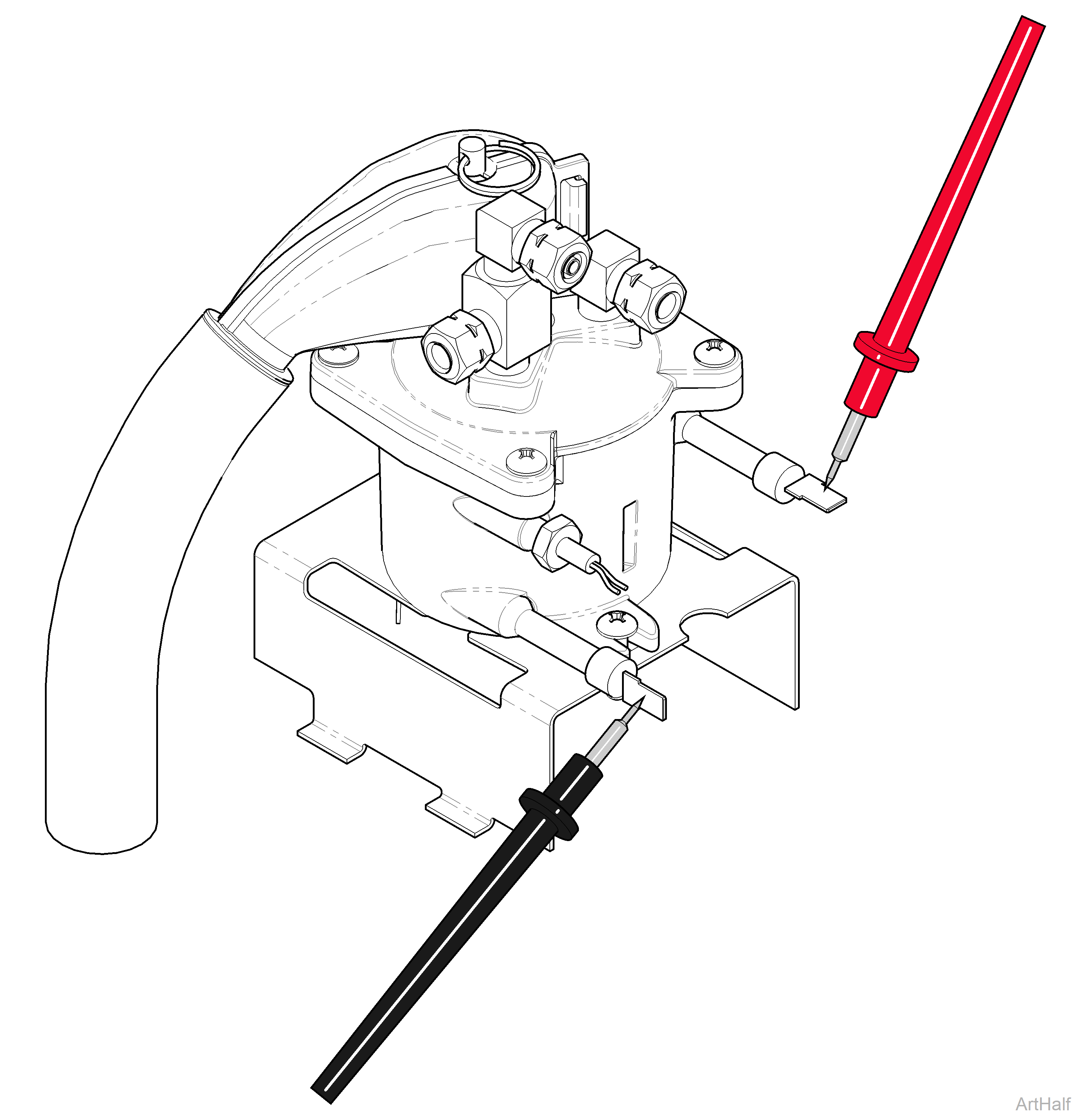
SN V1524268 thru Present Models Only: The boiler is energized continuously for the first 30 seconds of Dry Mode if the temperature is <240° F.
1.Tag and disconnect two wires from boiler.
2.Set meter to read ohms Ω.
3.Place meter probes on boiler terminals.
| Meter Reading | Required Action |
|---|---|
|
115 VAC Models: 9.8 to 10.8 Ω |
Boiler is OK |
| 230 VAC Models: 39.1 to 43.3 Ω | Boiler is OK |
| Out of range | Replace Boiler |
The dry heater test allows you to manually energize each of the two dry heaters independently for 15 second increments. There is a separate LED for each heater that illuminates to indicate current flow to that heater.
1.To turn current flow to dry heater ON / OFF press the <START> button.
•When the dry heater LED is ON the PC board is supplying current to that dry heater
•When the dry heater LED is OFF there is no current to dry heater.
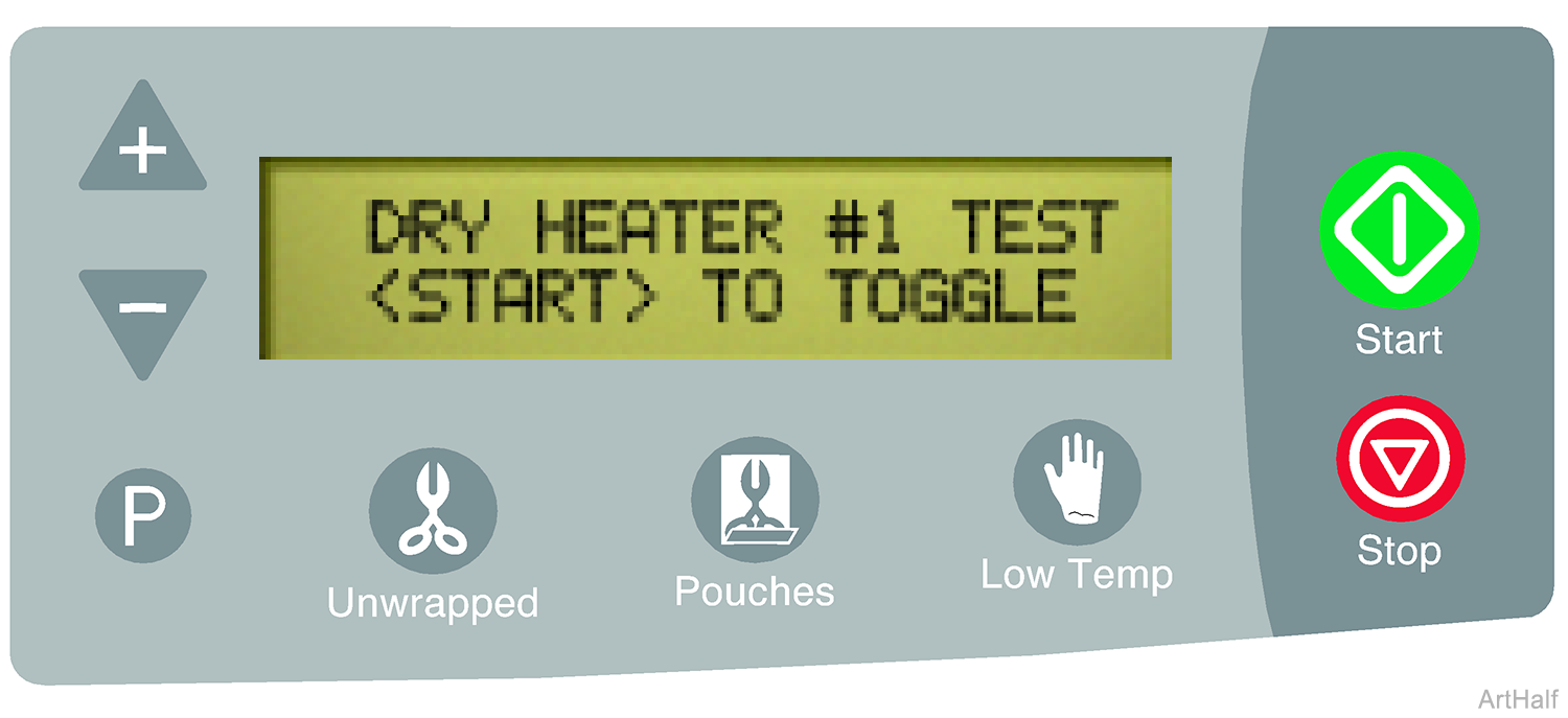
To verify proper operation

When the dry heater LED turns off after approximately 15 seconds, press the <STOP> button to advance to the Temperature Display Screen. The temperature of the dry heater #1 is shown as DH1. If the display does not reflect an increase in temperature, perform the Dry Heater Voltage Test below.
Wires should be connected to PC Board during dry heater voltage test.
1.Press <START> button so that dry heater LED is ON.
2.Set meter to read VAC.
3.Place meter probes on the Blue and Brown wires of J7 or J8.
| Meter Reading | Required Action |
|---|---|
|
Line voltage and voltage drops to zero after 15 seconds |
PC board is OK. Perform Dry Heater Resistance Test |
| No voltage or voltage doesn't drop to zero after 15 seconds | Replace PC board |
Press <STOP> button to advance the display to the next test.
Allow unit to cool before performing this test.
|
Model |
M3 |
| Serial Number | V1686974 and Prior, V1998086 to Present |
The dry heaters in these units have non-resettable thermostats that are integrated into the pressure vessel. If the test indicates an issue, the unit will have to be returned to Midmark for repair.
1.Disconnect dry heater wire harness from PC board J7 / J8.
2.Set meter to read ohms Ω.
3.Place meter probes on wire harness pins as shown. Check resistance at all three test points shown.
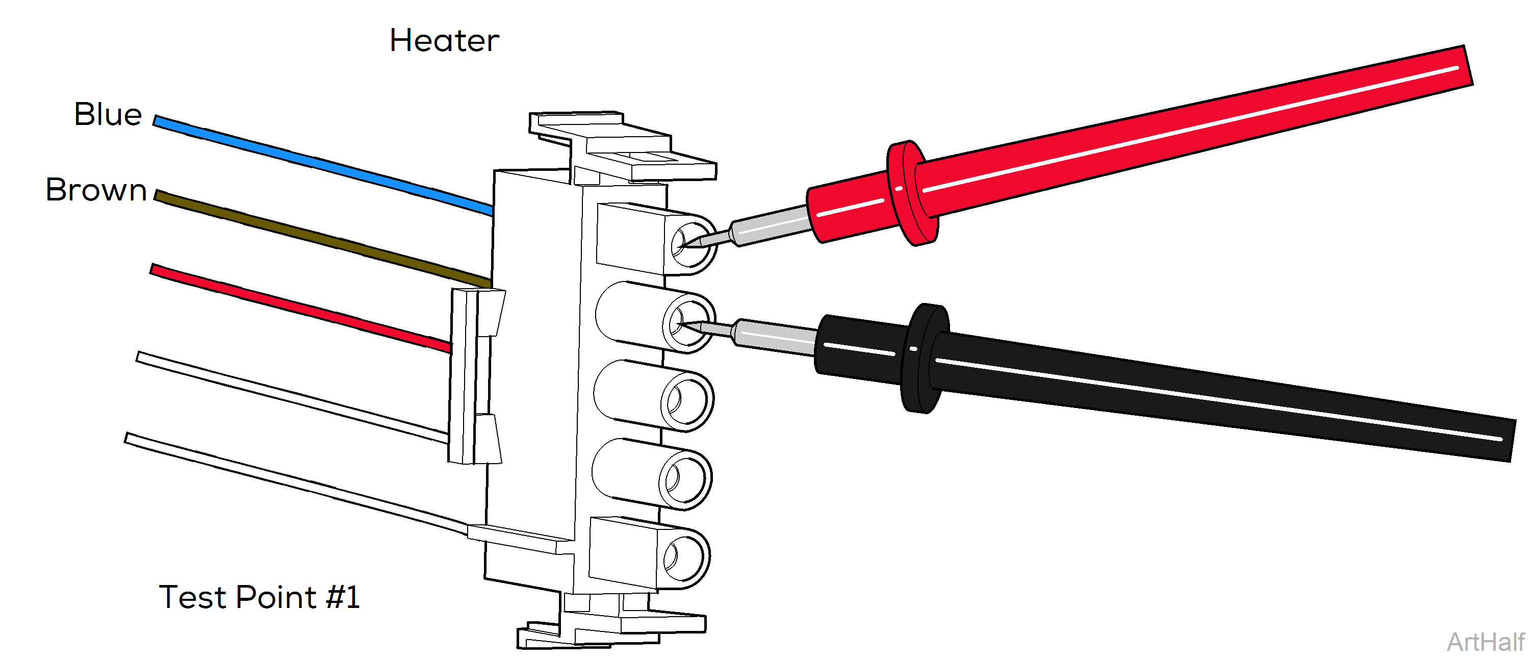
| Test Point #1 | |
|---|---|
| Meter Reading | Required Action |
|
115 VAC Models: 68 to 80 Ω |
Test Point #1 is OK |
| 230 VAC Models: 273 to 317 Ω | Test Point #1 is OK |
| Out of range | Contact Midmark Technical Service |
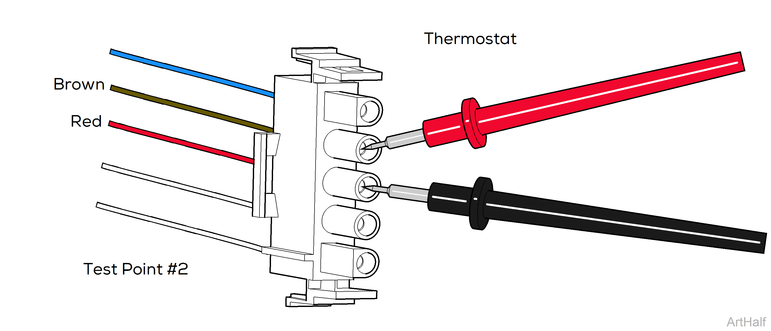
| Test Point #2 | |
|---|---|
| Meter Reading | Required Action |
|
0 Ω |
Test Point #2 is OK |
| OL or >0 | Contact Midmark Technical Service |
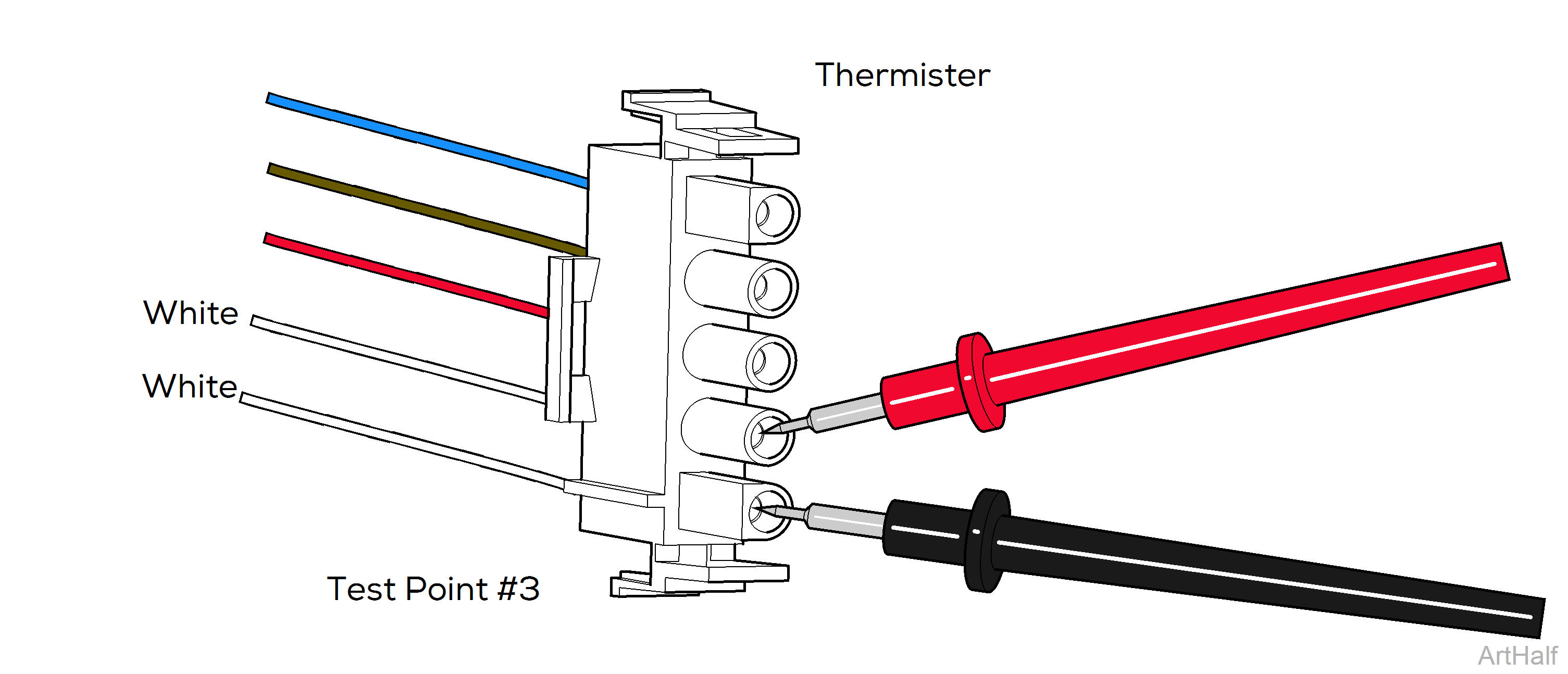
| Test Point #3 | |
|---|---|
| Meter Reading | Required Action |
|
1.05 to 1.1 kΩ at room temperature |
Test Point #3 is OK |
| OL or 0 Ω at room temperature | Contact Midmark Technical Service |
|
Model |
M3 |
| Serial Number | V1686975 to V1998085 |
The dry heaters in these units have resettable thermostats that are integrated into the pressure vessel. Allow the unit to cool then turn the power off to reset thermostats before performing this test. If the test indicates an issue, the unit will have to be returned to Midmark for repair.
1.Disconnect dry heater wire harness from PC board J7 / J8.
2.Set meter to read ohms Ω.
3.Place meter probes on wire harness pins as shown. Check resistance at all three test points shown.

| Test Point #1 | |
|---|---|
| Meter Reading | Required Action |
|
115 VAC Models: 38 to 44 Ω 230 VAC Models: 152 to 176 Ω |
Test Point #1 is OK |
| Out of range | Contact Midmark Technical Service |

| Test Point #2 | |
|---|---|
| Meter Reading | Required Action |
|
0 Ω |
Test Point #2 is OK |
| OL or >0 | Contact Midmark Technical Service |

| Test Point #3 | |
|---|---|
| Meter Reading | Required Action |
|
1.05 to 1.1 kΩ at room temperature |
Test Point #3 is OK |
| OL or 0 Ω at room temperature | Contact Midmark Technical Service |
This test allows you to manually energize the condensation heater. The condensation heater LED illuminates to indicate current flow to the heater.
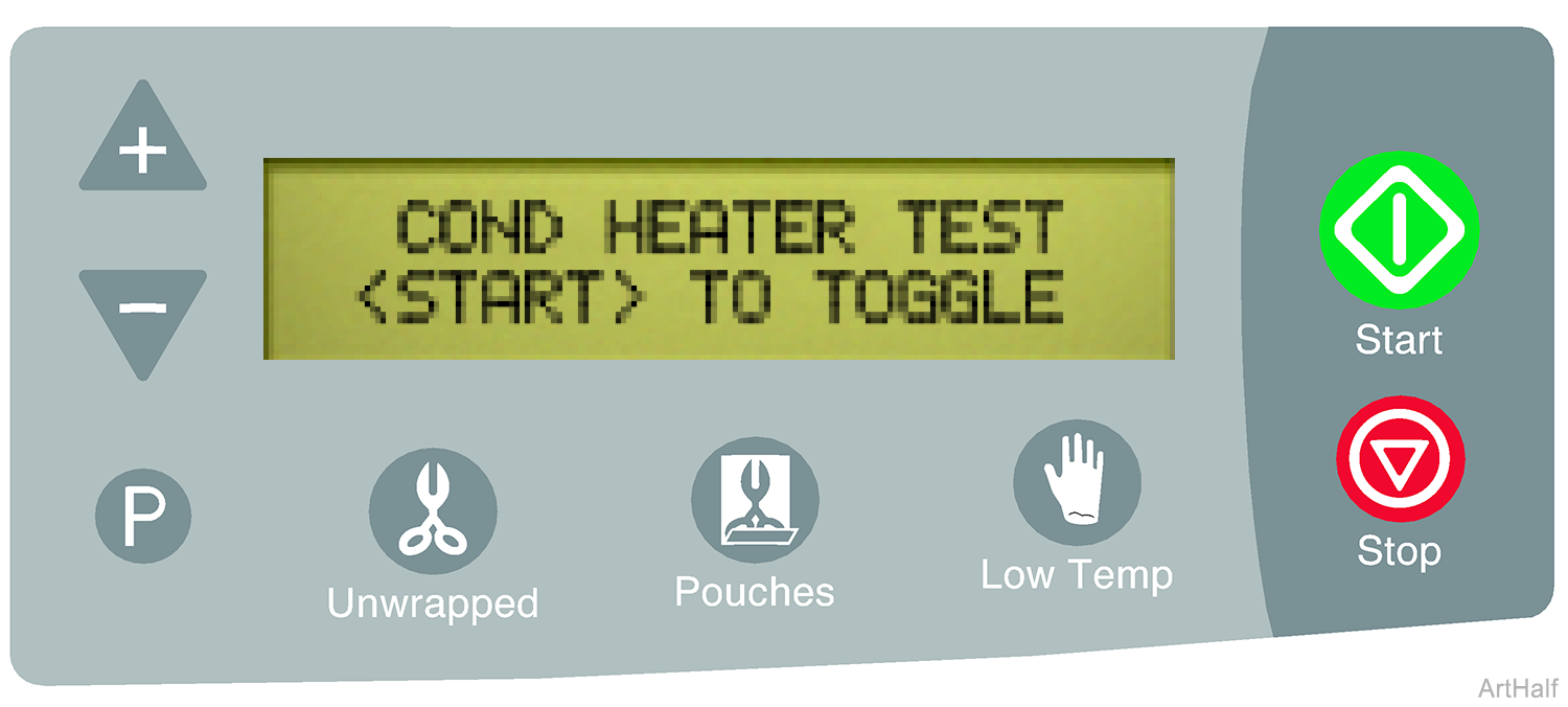
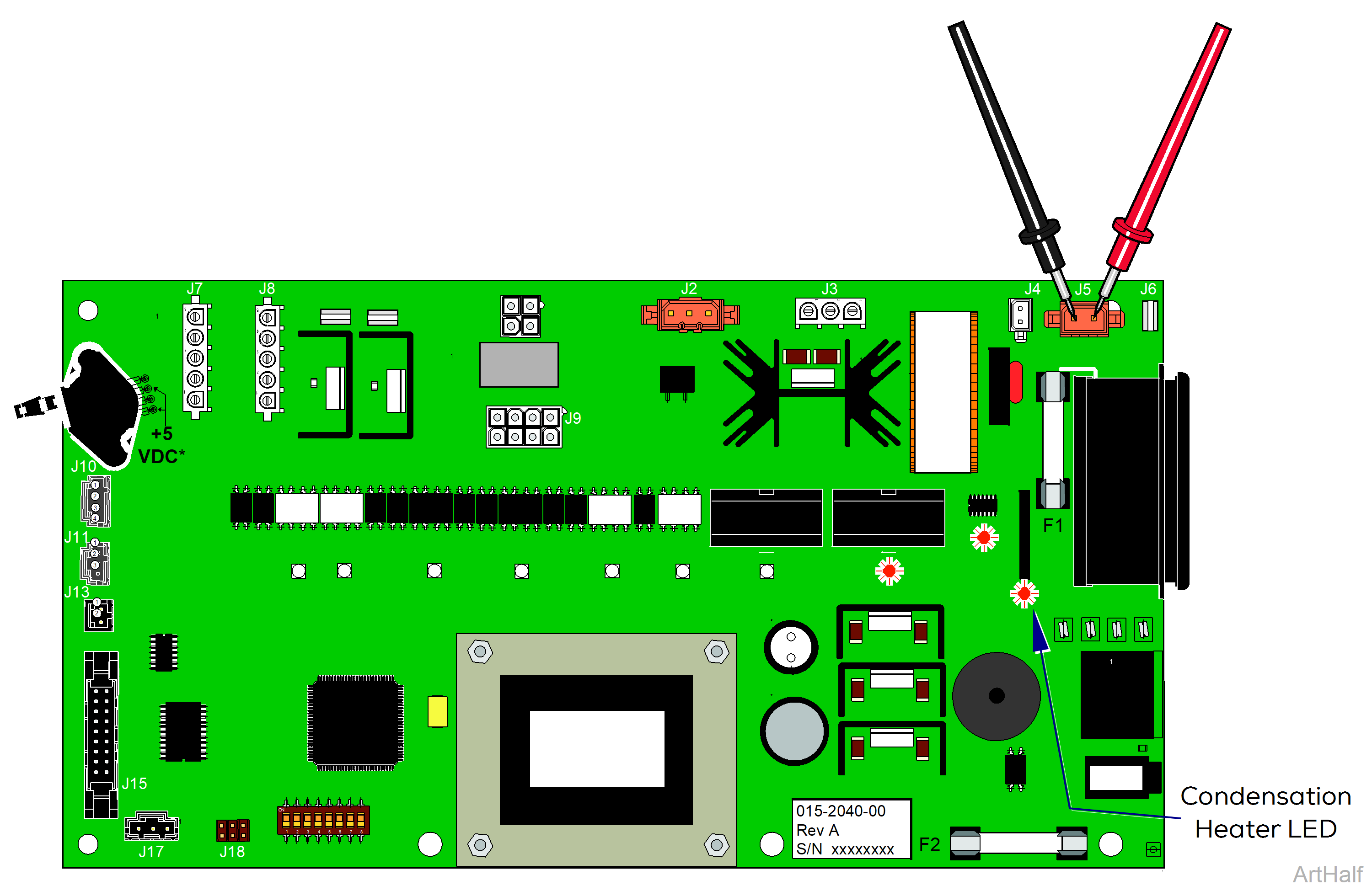
1.To turn current flow to condensation heater ON / OFF Press the <START> button
•When the condensation heater LED is ON the PC board is supplying current to the heater.
•When the condensation heater LED is OFF there is no current to heater.
To verify proper operation
After the heater has been ON for approx. 1 minute, touch the front panel above the chamber. This area should feel warm. If the panel does not feel warm, perform the Condensation Heater Voltage Test.
1. Disconnect heater harness from PC board J5.
2. Press <START> button so that heater LED is ON.
3. Set meter to read VAC.
4. Place meter probes on pins of J5 on PC board.
| Meter Reading | Required Action |
|---|---|
|
Line voltage |
PC board is OK. Perform Condensation Heater Resistance Test |
| No voltage | Replace PC board |
Press <STOP> button to advance the display to the next test.
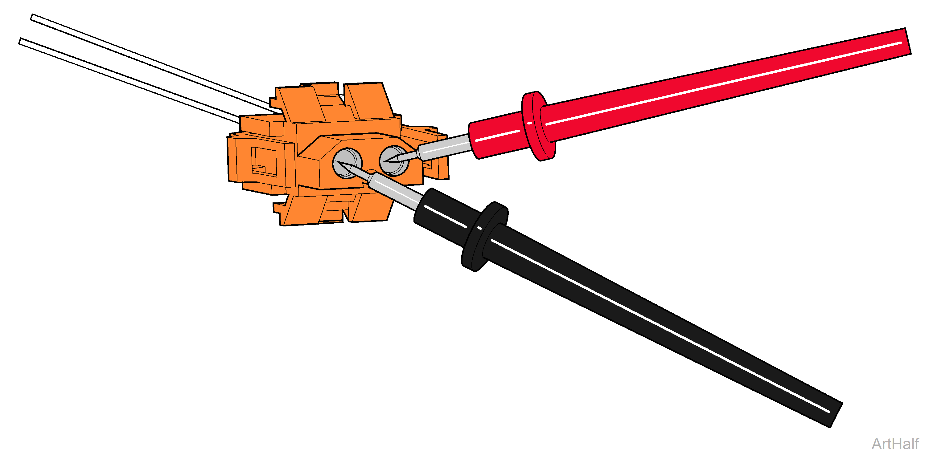
1.Disconnect Condensation heater wire harness from PC board J5.
2.Set meter to read ohms Ω.
3.Place meter probes on wire harness pins as shown.
| Meter Reading | Required Action |
|---|---|
|
115 VAC Models: 720 Ω, ± 10% |
Test Point #1 is OK |
| 230 VAC Models: 2880 Ω, ± 10% | Test Point #1 is OK |
| Out of range | Replace Condensation Heater |
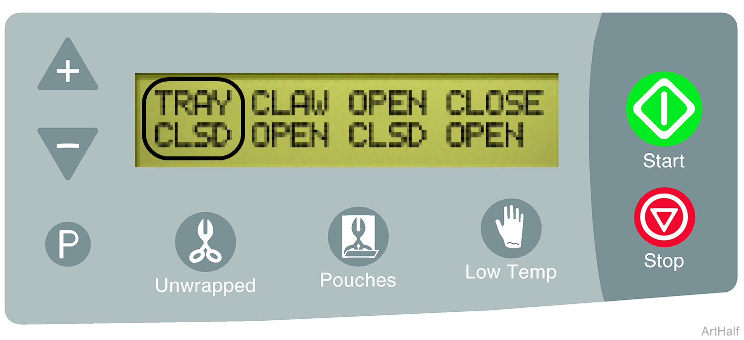
To ensure accurate readings, the door / tray assembly must be positioned so the tray switch is tripped (CLSD).
This screen shows the status of the Tray Switch (TRAY), Claw Switch (CLAW), Door Open Switch (OPEN) and the Door Closed Switch (CLOSE).
The status of the switch is shown directly below the switch display. The status (CLSD / OPEN) should accurately reflect the current position of that switch. The switches can be manually tripped / untripped to verify the reading is correct.
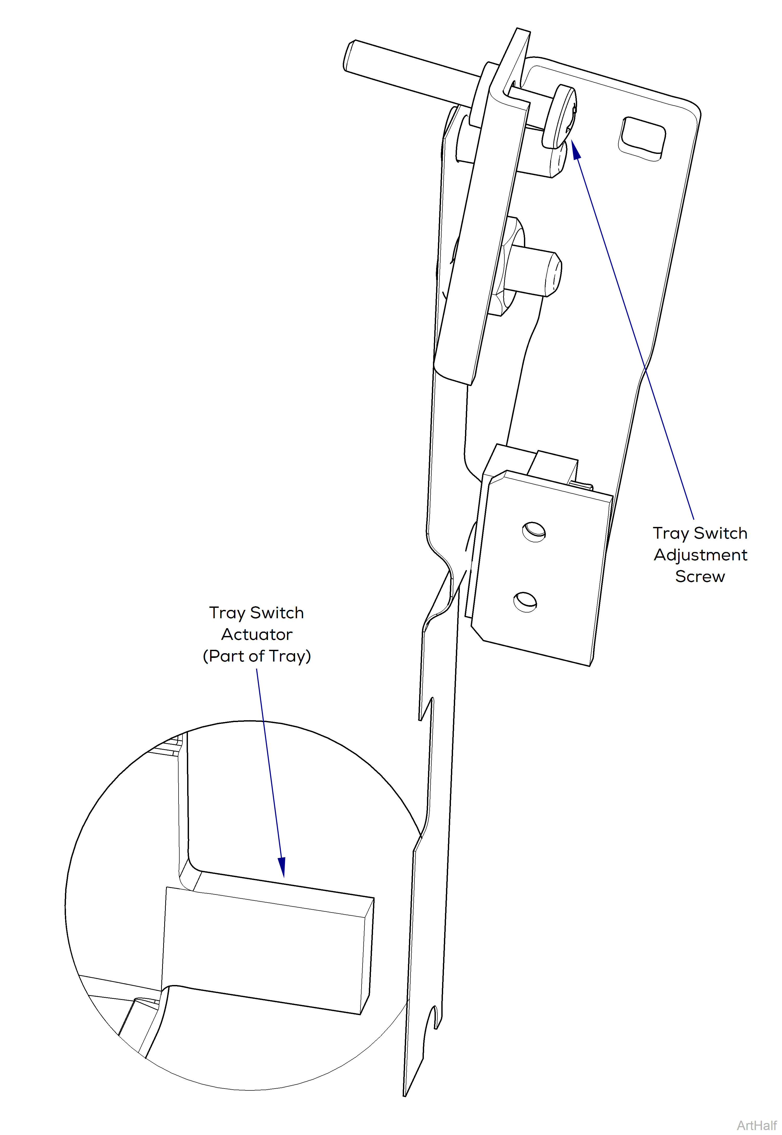
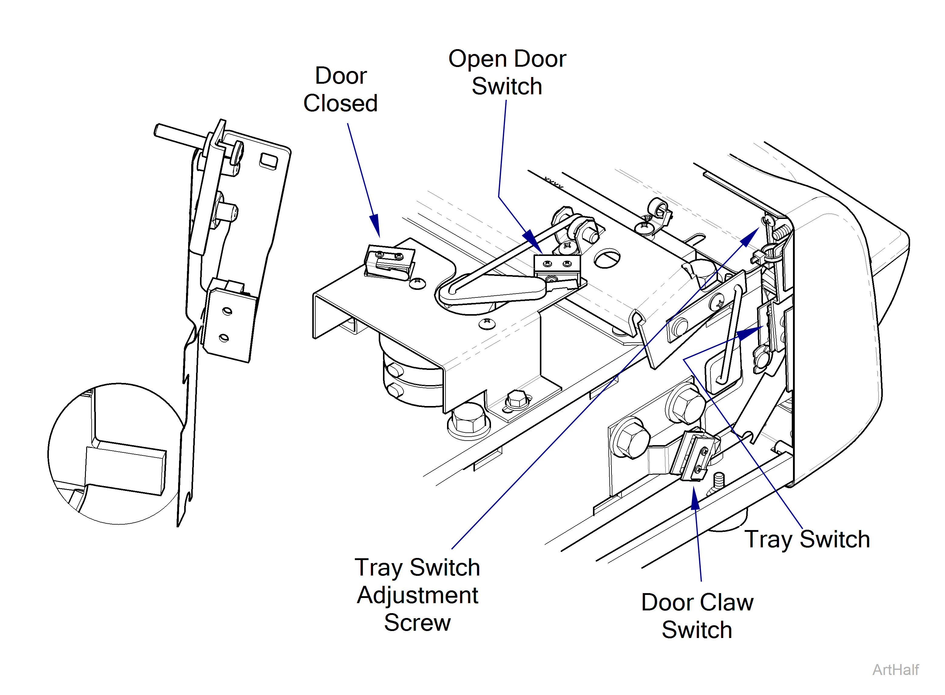
Tray Switch (TRAY) Adjustment
Some procedures require power to be connected with covers removed. Line voltage is present. Use extreme caution to prevent electric shock.
If your sterilizer is not equipped with the Photo Interrupter DO NOT adjust the Tray Switch Adjustment Screw. Contact Midmark Technical Service for assistance.
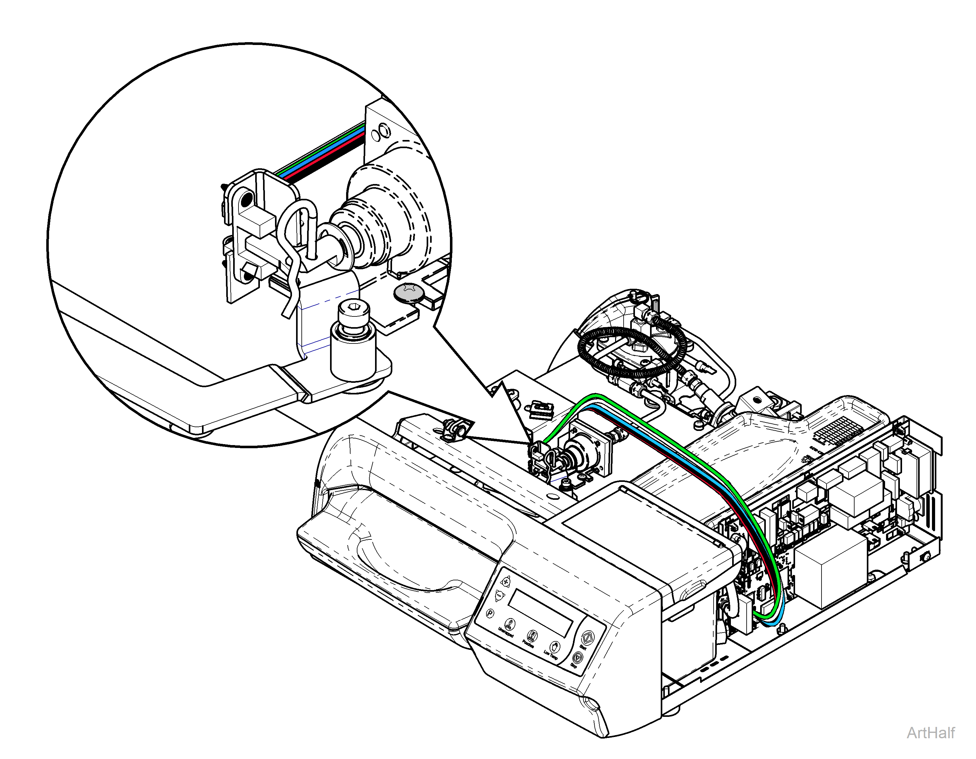
1.Insert the tray and position it where the tray initially crest the bump in the chamber right before it drops into the fully inserted position.
2.Adjust the tray switch adjustment screw so it shows the tray switch closed with the tray in this position.
Press <STOP> button to advance the display to the next test.
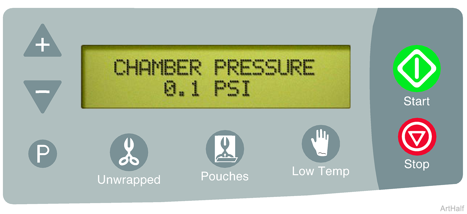
This screen shows the amount of pressure currently in the chamber. With the door open, the display should read 0.1 PSI.
Press <STOP> button to advance the display to the next test.
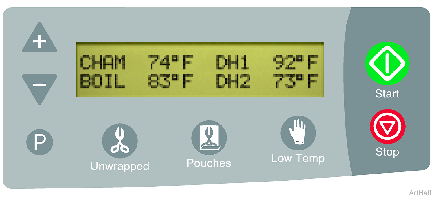
This screen displays the temperature inside the chamber CHAM, inside the boiler BOIL and for the two dry heaters DH1 and DH2.
Press <STOP> button to advance the display to the next test.
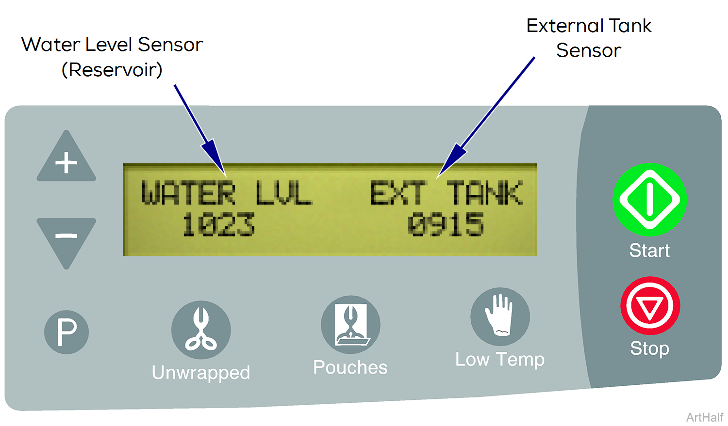
The sensor status is displayed in a numeric code.
This screen shows the status of the water level sensor in the reservoir (WATER LVL) and the sensors in the external condensing tank (EXT TANK).
| Water Level Sensor (reservoir) | |
|---|---|
| # Code | Description |
| 1023 | Water level OK |
| 0 | Low water |
| External Tank Sensor | |
|---|---|
| # Code | Description |
| > 950 | Tank disconnected |
| 910 - 920 | Water level OK |
| < 750 | Tank is full |
Press <STOP> button to advance the display to the next test.
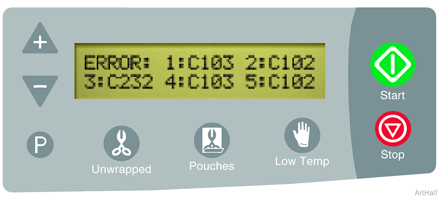
This screen shows the last five error codes stored in the unit. 1: indicates the most recent error code and 5: indicates the oldest.
To erase all five error codes from memory press <START> button.
To retain the error codes in memory press <STOP> button.
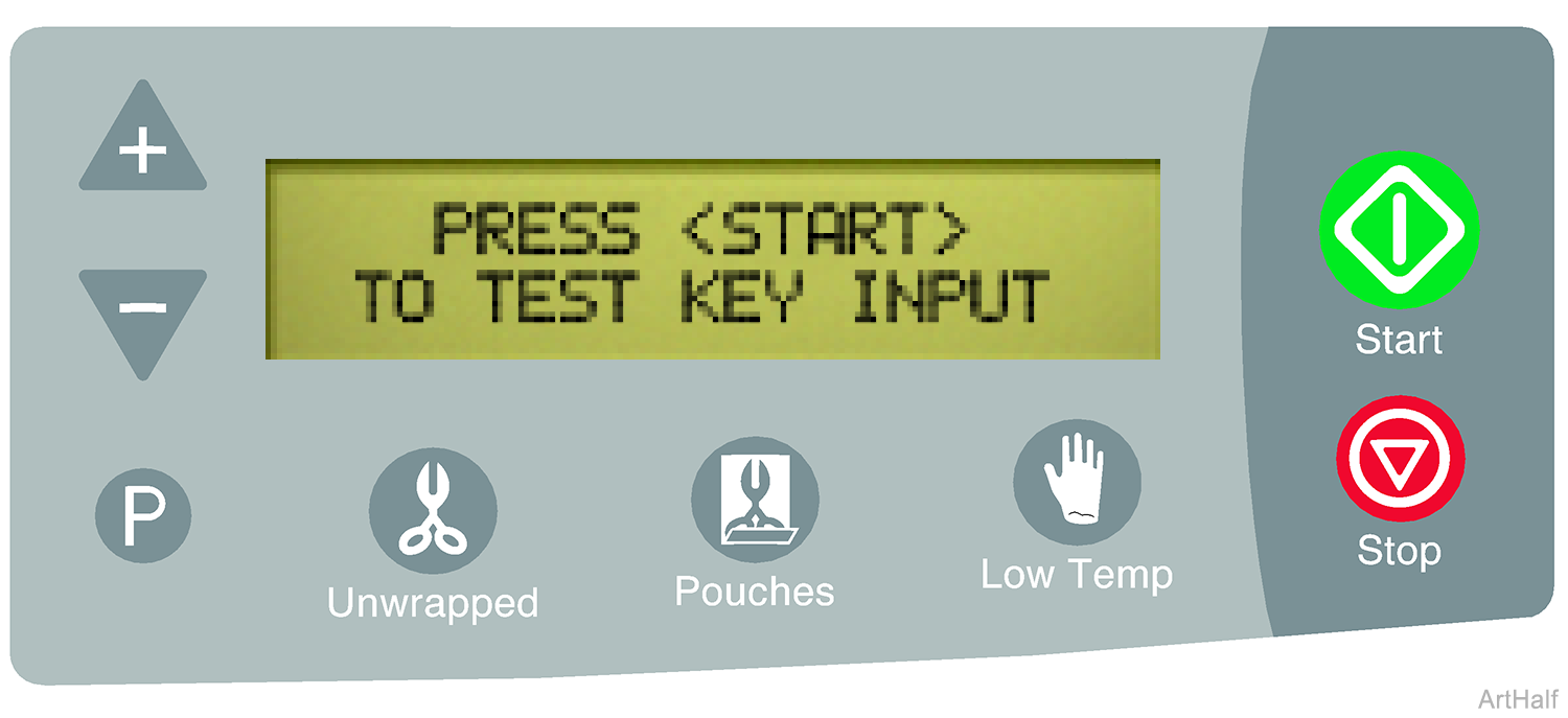
To test the functionality of the touch pad press <START> button.
When the designated button is pressed, you will hear a single beep and the test will advance to the next button. This indicates the button is functioning properly. Continue for all remaining buttons.
Point 1: Door / Tray Gasket.
1.Check for water or steam leakage from around Door / Tray.
2.Clean or replace Door / Tray Gasket.
Point 2: Vent Valve.
1.Check plastic tube connecting unit to the external condensing tank for a flow of steam and hot water in between vent valve operations.
2.Clean or replace Vent Valve.
Point 3: Pressure Relief Valve.
1.Check for water or steam leakage from under the back left hand corner of sterilizer.
2.Pop off and re-seat, or replace Pressure Relief Valve..
Point 4: Pressure Sensor Tubing.
1.Check for water or steam leakage onto main PC board where pressure sensor tubing attaches to pressure transducer.
2.Reattach or replace Pressure Sensor Tubing.
Point 5: Fittings.
1.Check all plumbing fitting connections for leakage.
2.Tighten or replace fittings.
Point 6: Pump Check Valve.
1.Check the pump to boiler water line for air bubbles pushing back into the pump when the sterilizer is building pressure.
2.Replace Pump.
The sensor(s) must be tested at room temperature.
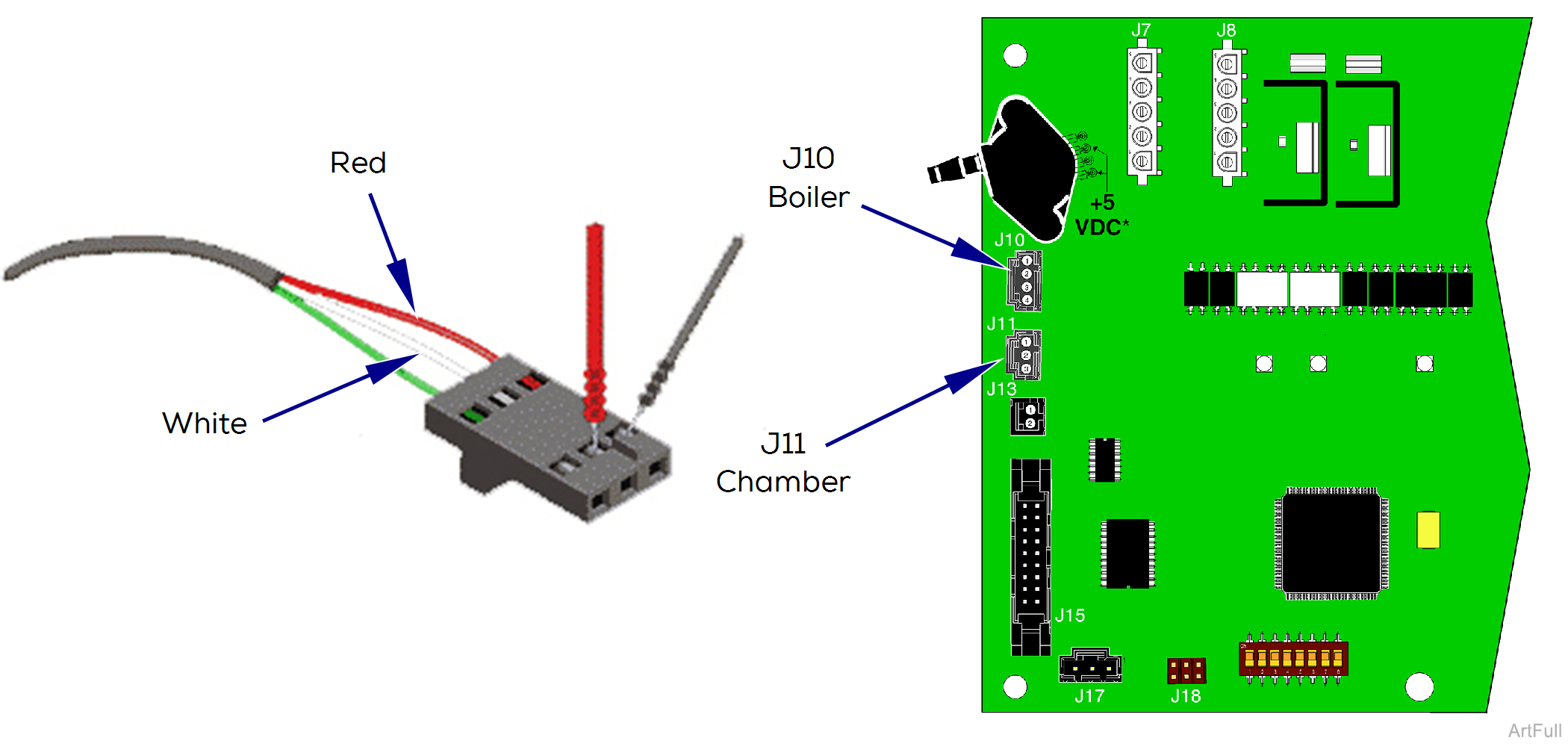
Boiler Temperature Sensor Test
1.Disconnect sensor harness from J10 on PC board.
2.Set meter to 2k ohms Ω.
3.Place meter probes on the red and white wires. The acceptable reading is 1.07k to 1.1k ohms Ω.
Chamber Temperature Sensor Test
1. Disconnect sensor harness from J11 on PC board.
2.Set meter to 2k ohms Ω.
3.Place meter probes on the red and white wires. The acceptable reading is 1.07k to 1.1k ohms Ω.
4.Clean sensor with mild soap and distilled water.
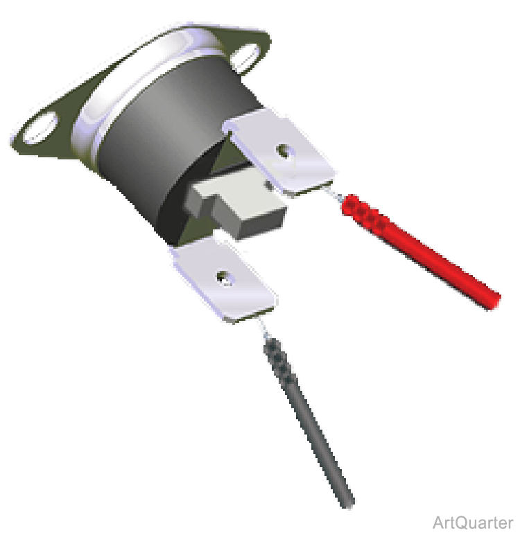
The thermostat is located under the boiler assembly. A manual reset button is located in between the terminals of the thermostat.
Overheat Thermostat must be tested at room temperature.
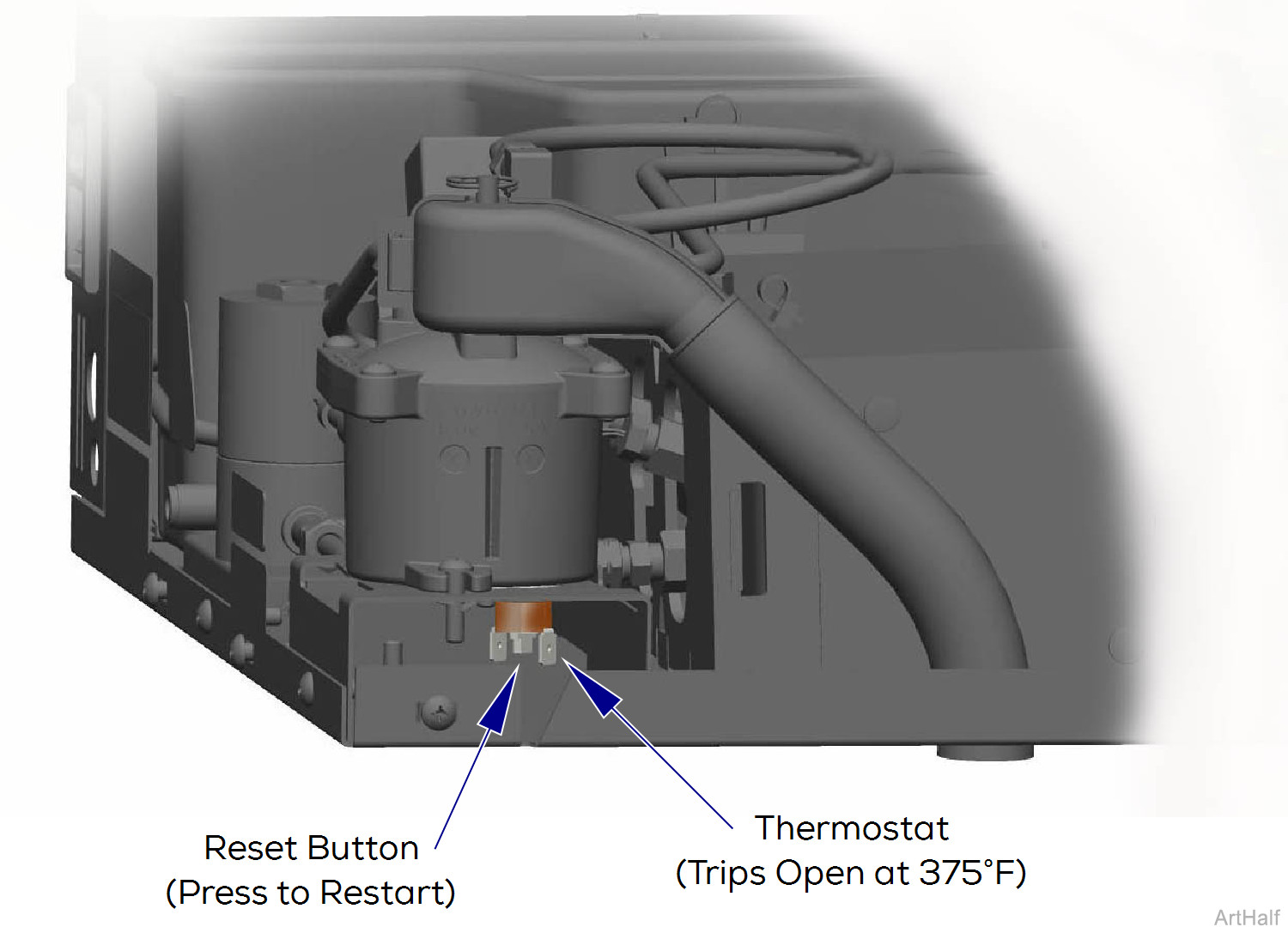
1.Disconnect wires from thermostat.
2.Place meter probes on thermostat terminals. Set meter to ohms Ω.
| With switch Untripped | |
|---|---|
| Meter Reading | Required Action |
| Any resistance reading | Switch is good. |
| OL | Replace switch |
Used with New Style PC Boards (Serial Number V1408970 thru Present)
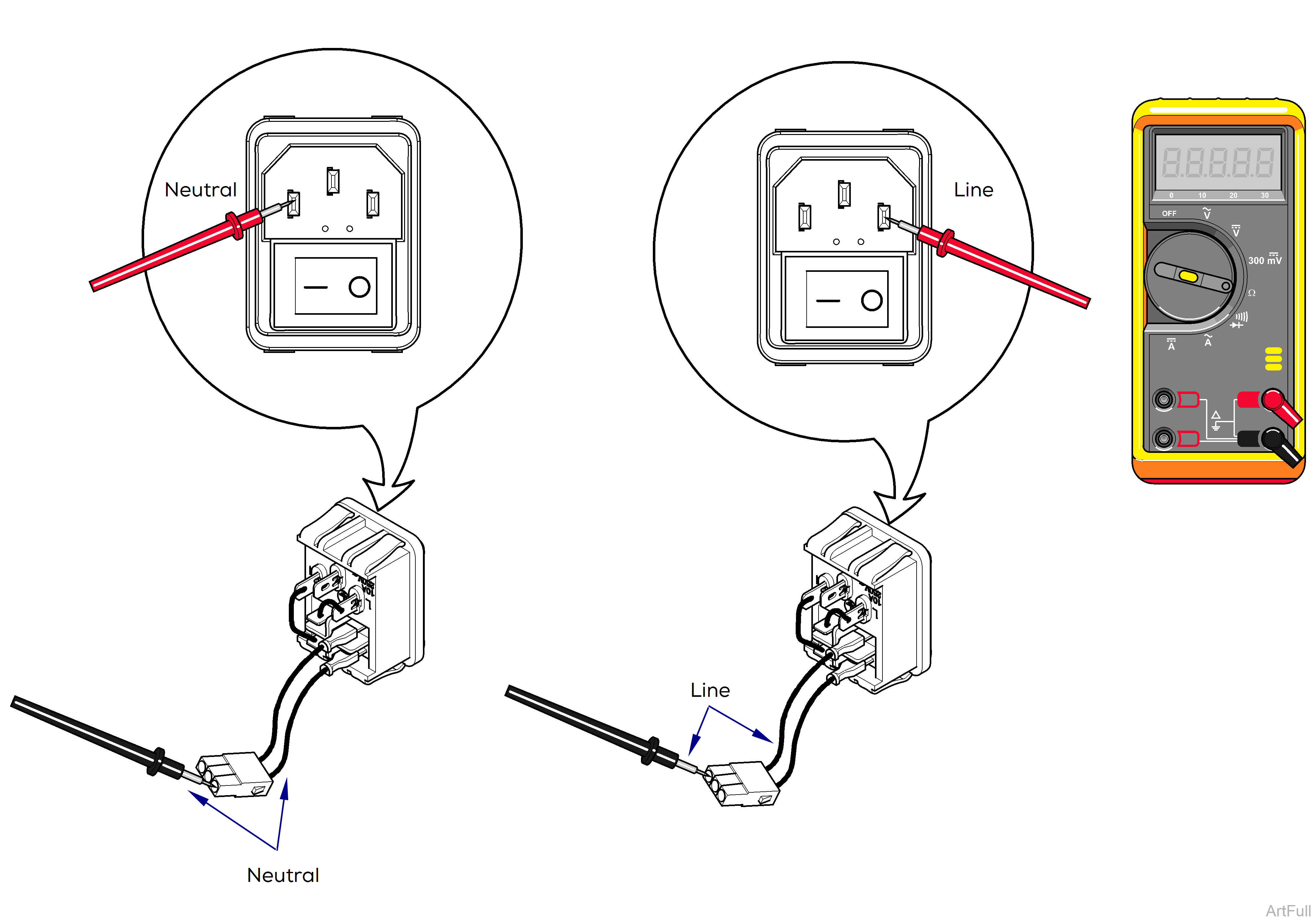
1.Unplug unit from power source.
2.Remove top cover. Refer to: Top Cover
3.Disconnect switch connector from PC board.
4.Set meter to check continuity.
5.Flip switch to OFF and probe both neutral and line sides.
6.Flip switch to ON and probe both neutral and line sides.
| With switch Off | |
|---|---|
| Meter Reading | Required Action |
| OL | Switch is good. |
| Any other reading | Replace switch |
| With switch On | |
|---|---|
| Meter Reading | Required Action |
| 0 Ohms | Switch is good. |
| Any other reading | Replace switch |
Used with New Style PC Boards
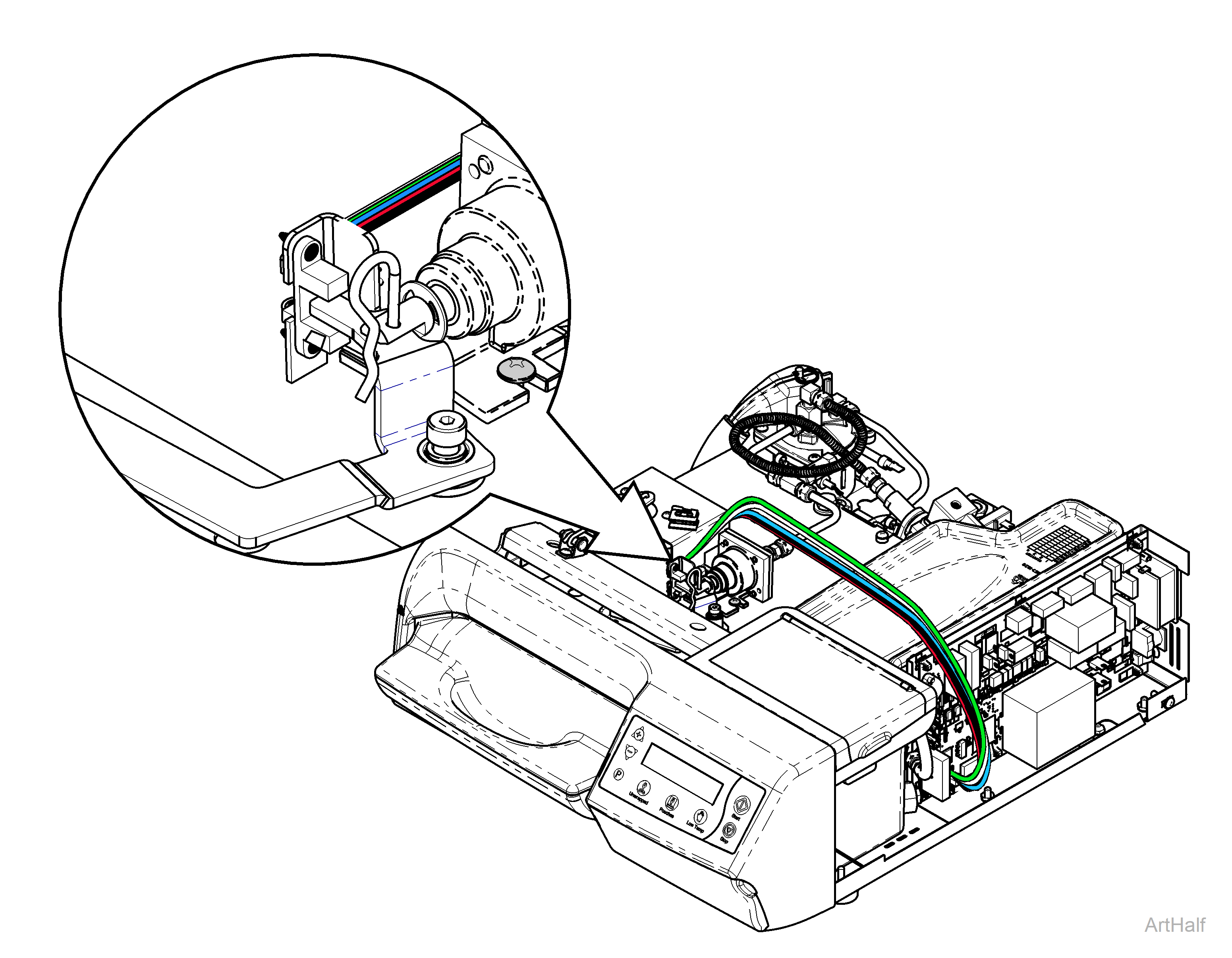
Completing this check will verify that the hardware is or is not working back to the processor. If it is not working the photo interrupter will need to be replaced.
1.Remove top cover. Refer to: Top Cover
2.Verify photo interrupter is connected to PC board at J12.
3.Verify no debris on photo interrupter sensor. May clean with q-tip.
4.Activate Service Diagnostics and scroll to Interlock disengaged on display screen.
5.Pull cotter pin of plunger forward, screen display should read, Interlock engaged.
| Display Reading | Position | Required Action |
|---|---|---|
| Interlock Engaged | Pressurized | Photo interrupter is good. |
| Interlock Disengaged | Depressurized | Photo interrupter is good. |
| Anything different than above states. | Any | Replace photo interrupter. |

