M9/M11 Sterilizer Flow Diagram
To prevent risk of shock always disconnect power before removing covers or performing any service procedure.
Some procedures require power to be connected with covers removed. Line voltage is present. Use extreme caution to prevent electric shock.
|
Model |
M9 -033 / -034 | M11 -033 / -034 |
| Serial Number | All | All |
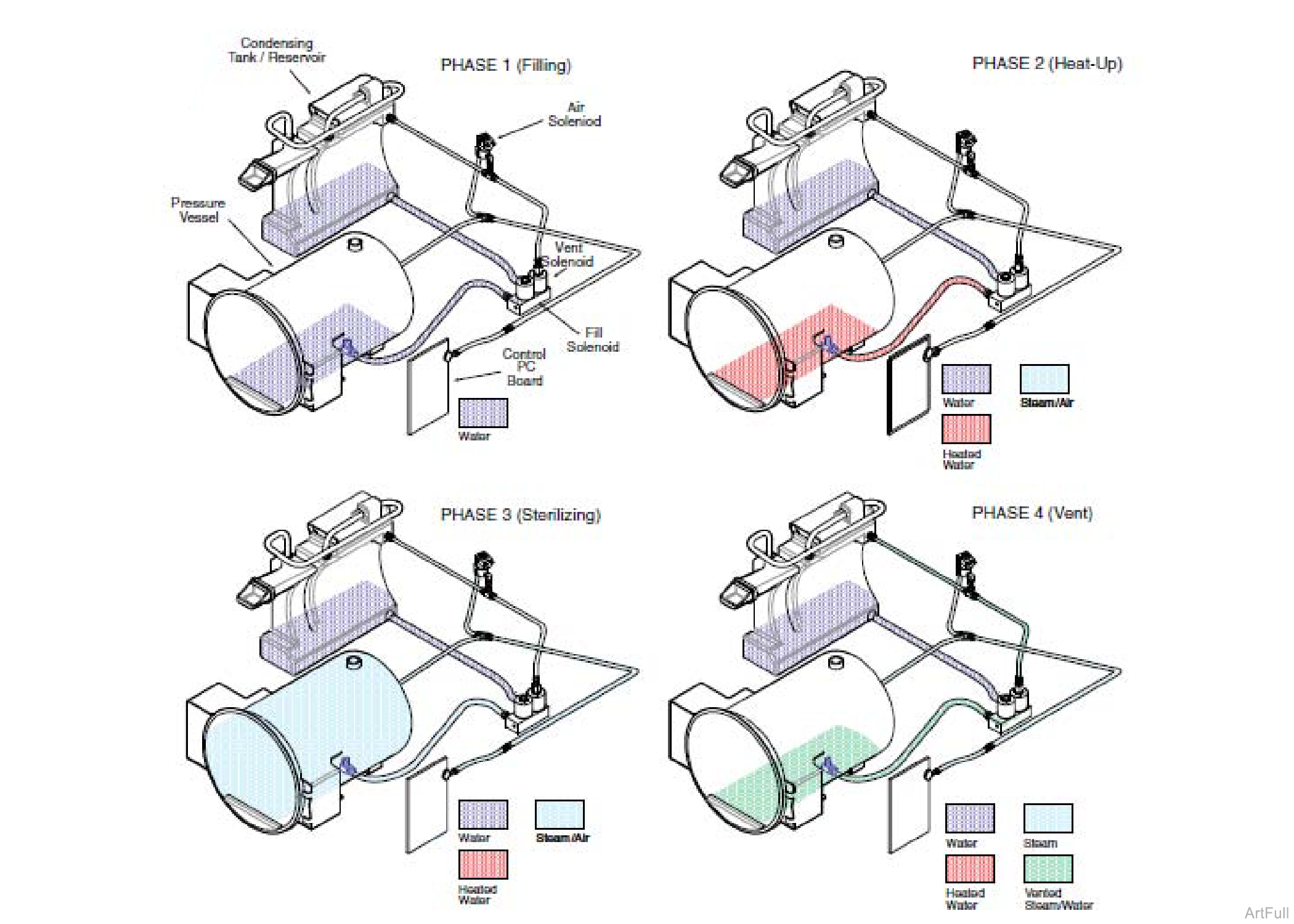
These diagrams illustrate the flow of water, heated water, steam, and vented steam thru the sterilizer during each phase of a cycle.

|
Model |
M9 -033 / -034 | M11 -033 / -034 | M9D -022 |
| Serial Number | All | All | All |
These diagrams illustrate the flow of water, heated water, steam, and vented steam thru the sterilizer during each phase of a cycle.

|
Model |
M9 -040 thru -042 | M11 -040 thru -042 | M9D -042 |
| Serial Number | All | All | All |
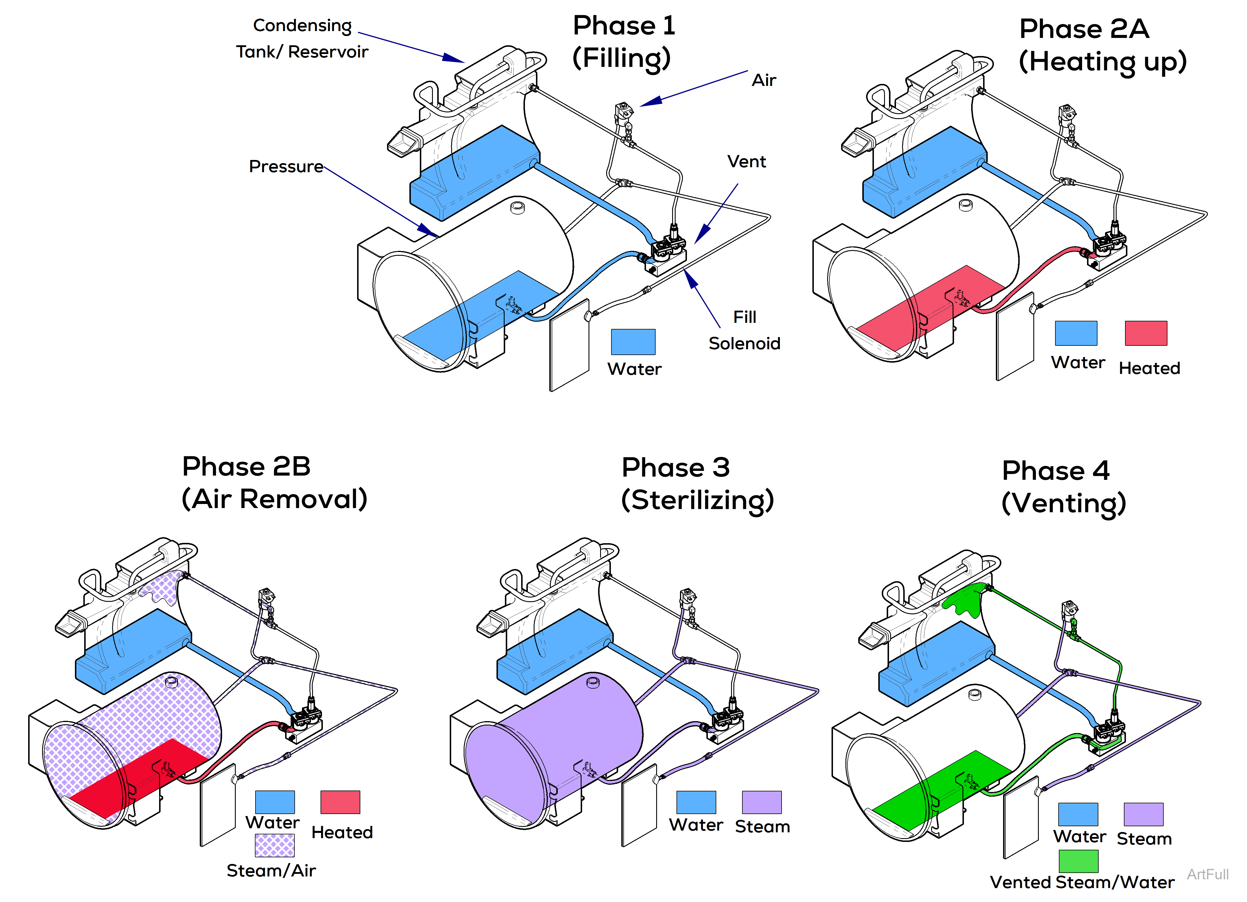
These diagrams illustrate the flow of water, heated water, steam, and vented steam thru the sterilizer during each phase of a cycle.

|
Model |
M9 -043 | M11 -043 |
| Serial Number | All | All |
These diagrams illustrate the flow of water, heated water, steam, and vented steam thru the sterilizer during each phase of a cycle.


