M9/M11 Sterilizer Main PC Board Test and Repair
|
Model |
M9M11 -020 thru -022, -033, -034 |
| Serial Number | All |
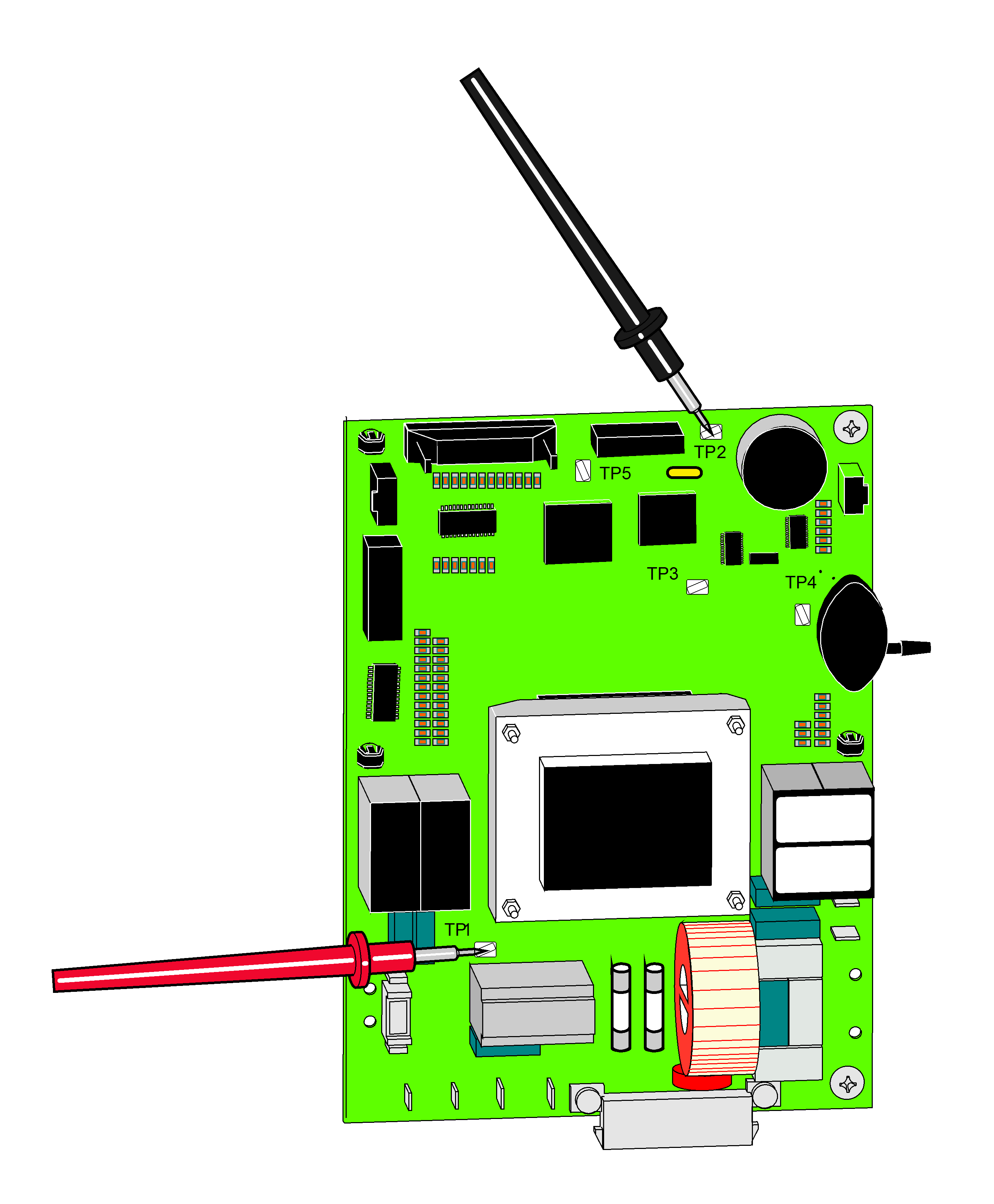
This test checks for proper supply voltage to all of the following components: Heating Element, Door Motor, Fill / Vent Valve, Air Valve.

1.Set meter to 20 VDC.
2.Place black meter probe on TP2 as shown.
3.Place red meter probe on TP1 as shown.
| Meter Reading | Required Action |
|---|---|
|
Acceptable range: 10 to 14 VDC |
Main PC board is OK |
|
Any reading out of the acceptable range |
Replace Main PC board |
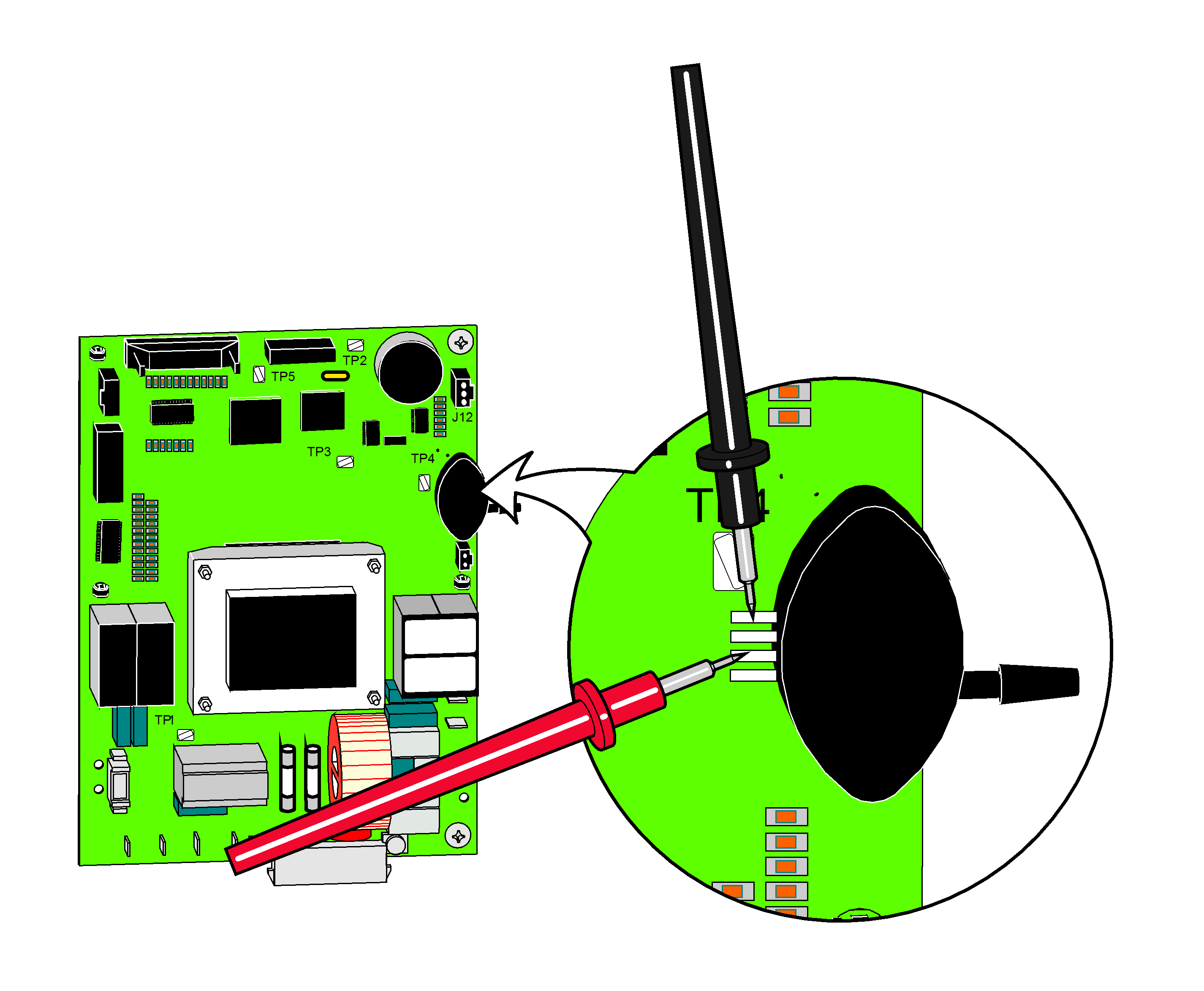
This test checks for proper supply voltage to pressure transducer.

*Pin position is referenced top to bottom. Top pin = 1, bottom pin=4
1.Set meter to 20 VDC.
2.Place meter probes on transducer pins 1 and 3* as shown.
| Meter Reading | Required Action |
|---|---|
|
Acceptable range: 4.0 to 6.0 VDC |
Main PC board is OK |
|
Any reading out of the acceptable range |
Replace Main PC board |
|
Model |
M9M11 -040 thru -043 |
| Serial Number | All |
Some procedures require power to be connected with covers removed. Line voltage is present. Use extreme caution to prevent electric shock.

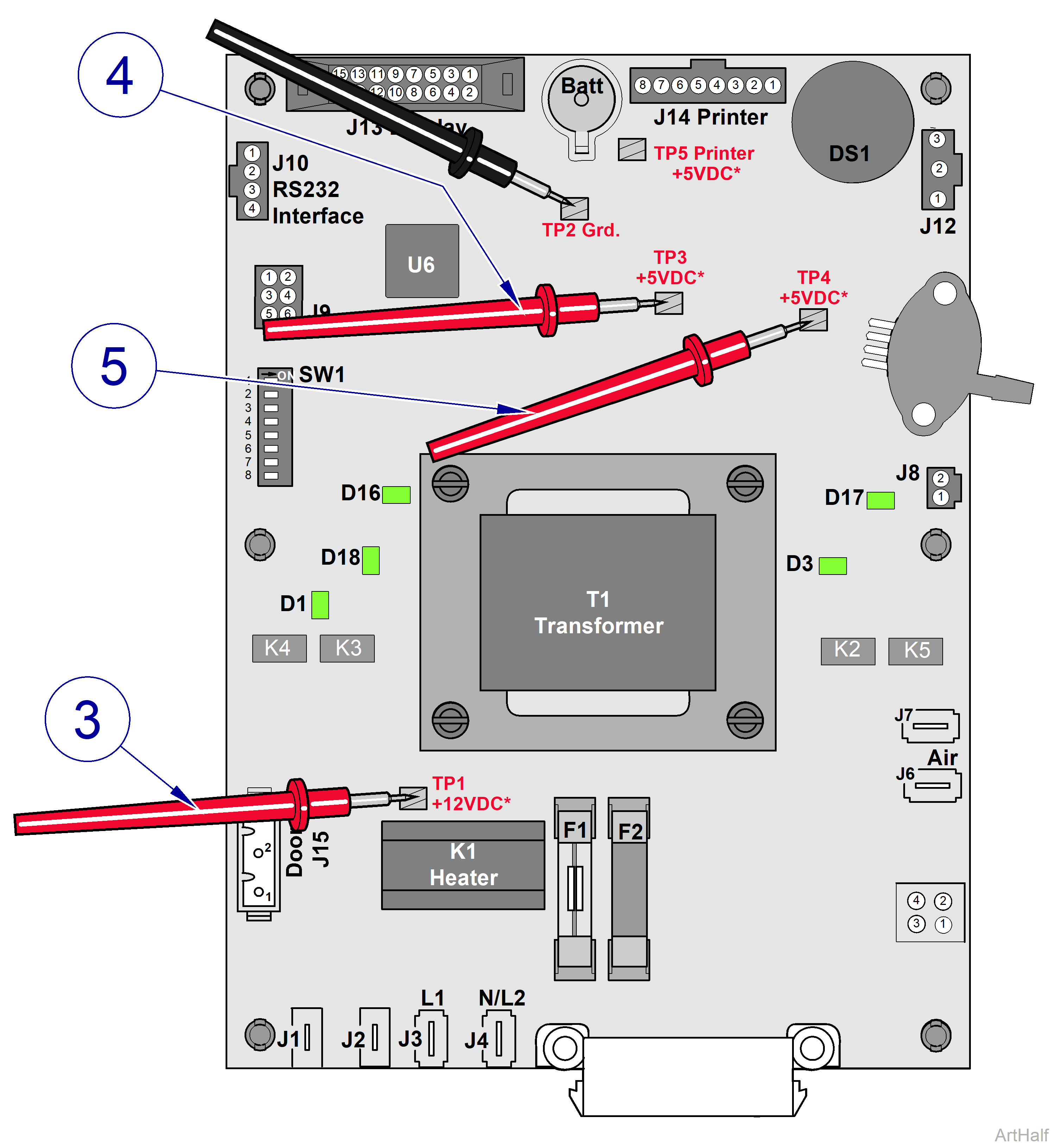
1.Set meter to 20 VDC.
2.Place black meter probe on TP2 as shown.
3.Place red meter probe on TP1 as shown. +12 VDC
4.Place red meter probe on TP3 as shown. +5 VDC
5.Place red meter probe on TP4 as shown. +5 VDC
| Meter Reading | Required Action |
|---|---|
| TP2 - TP1 acceptable range: 10 to 14 VDC | Main PC board is OK |
| TP 2 - TP3 and TP 2 - TP4 acceptable range: 4 to 6 VDC |
Main PC board is OK |
| Any reading out of the acceptable range |
Replace Main PC board |
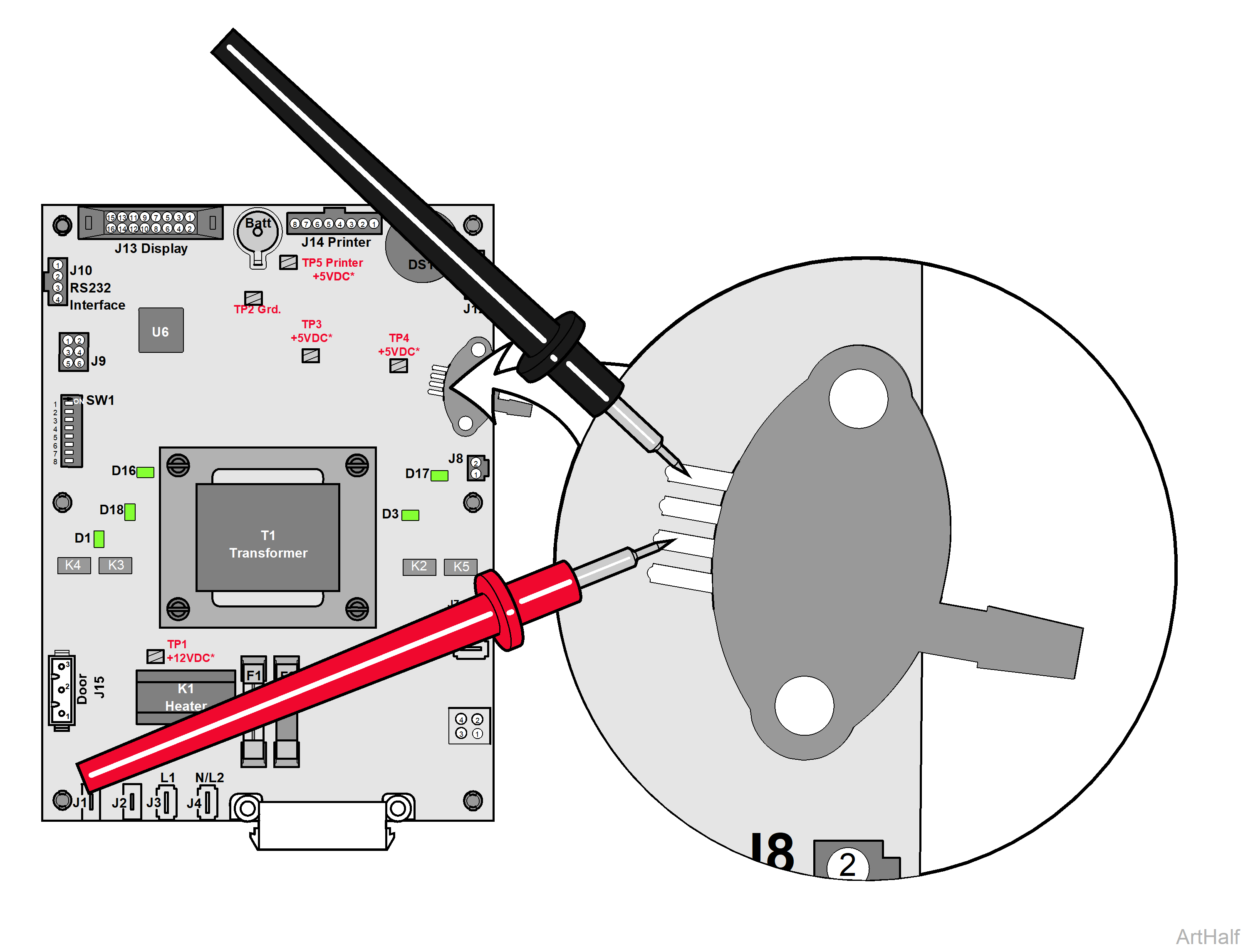
This test checks for proper supply voltage to pressure transducer.

1.Set meter to 20 VDC
2.Place meter probes on transducer pins 1 and 3* as shown.
*Pin position is referenced top to bottom. Top pin = 1, bottom pin=4
| Meter Reading | Required Action |
|---|---|
|
Acceptable range: 4 to 6 VDC |
Main PC board is OK |
|
Any reading out of the acceptable range |
Replace Main PC board |

