M9/M11 Sterilizer Power Up Mode Theory of Operation
To prevent risk of shock always disconnect power before removing covers or performing any service procedure.
Some procedures require power to be connected with covers removed. Line voltage is present. Use extreme caution to prevent electric shock.
The illustrations show the components that affect or are monitored during all cycle modes. Refer to the dropdowns for detailed descriptions of the Power Up Mode.
|
Model |
M9/9D -020 thru -022, -033, -034 |
M11/11D -020 thru -022, -033, -034 |
| Serial Number | All | All |
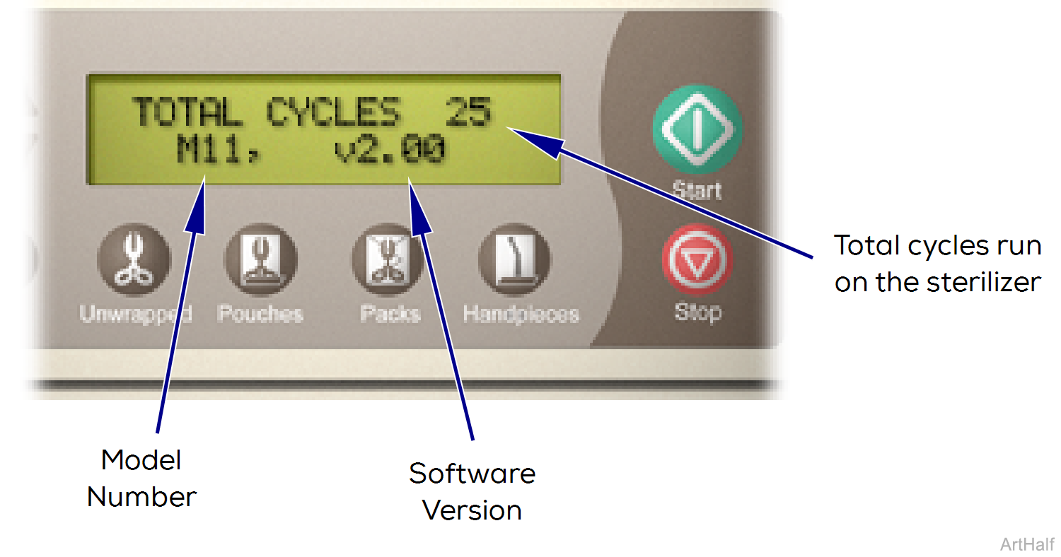
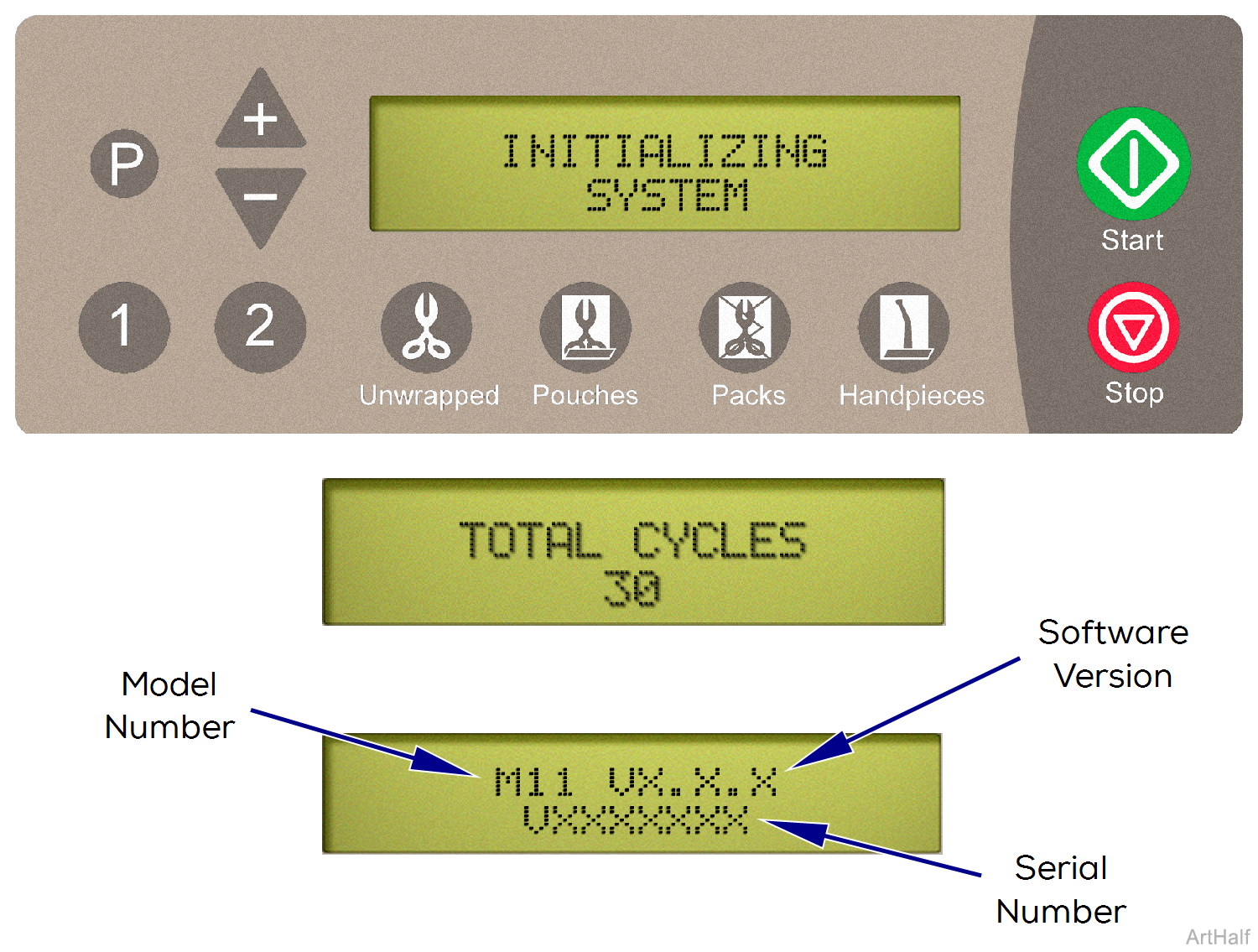
Each time power is reconnected, the display panel will show:
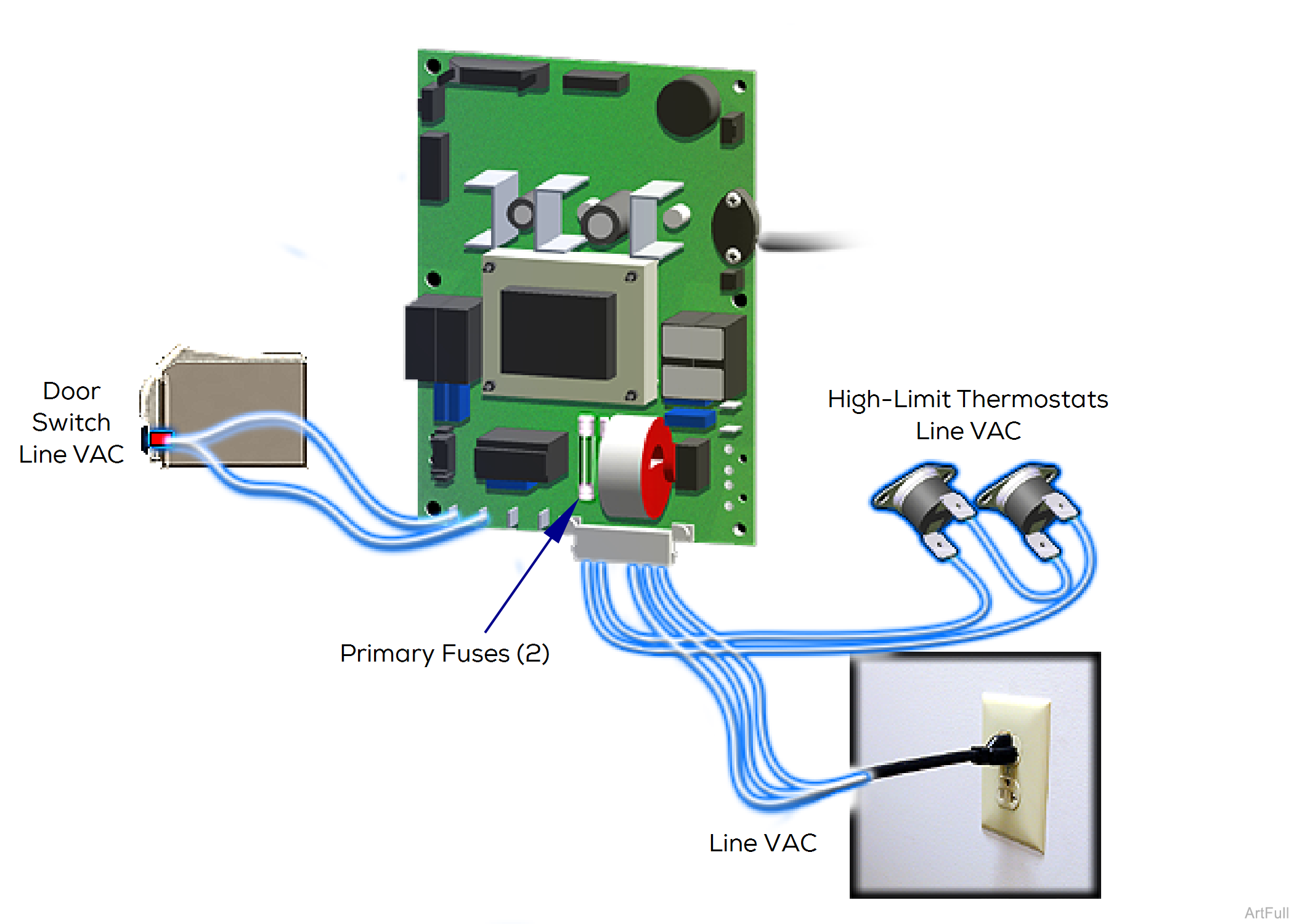
With the sterilizer's power cord properly connected, facility supply voltage is supplied to the Main PC Board thru the two primary fuses.
If either fuse is faulty, the sterilizer will have no power.
When power is supplied to the Main PC Board, current continuously flows thru the two normally closed High-Limit Thermostats. This circuit powers all line voltage components except Fan System.
If either thermostat opens for any reason (overheat or malfunction), the sterilizer will shut down until unit cools or thermostat is replaced.
Once a cycle is initiated, the Main PC Board continuously monitors the status of the Door Switch.
If an open door is detected, the cycle will not start. If the door switch opens during a cycle, the cycle will be terminated and the corresponding error code will appear in the display.
|
Model |
M9 -040 thru -043 | M9D -042 | M11 -040 thru -043 |
| Serial Number | All | All | All |
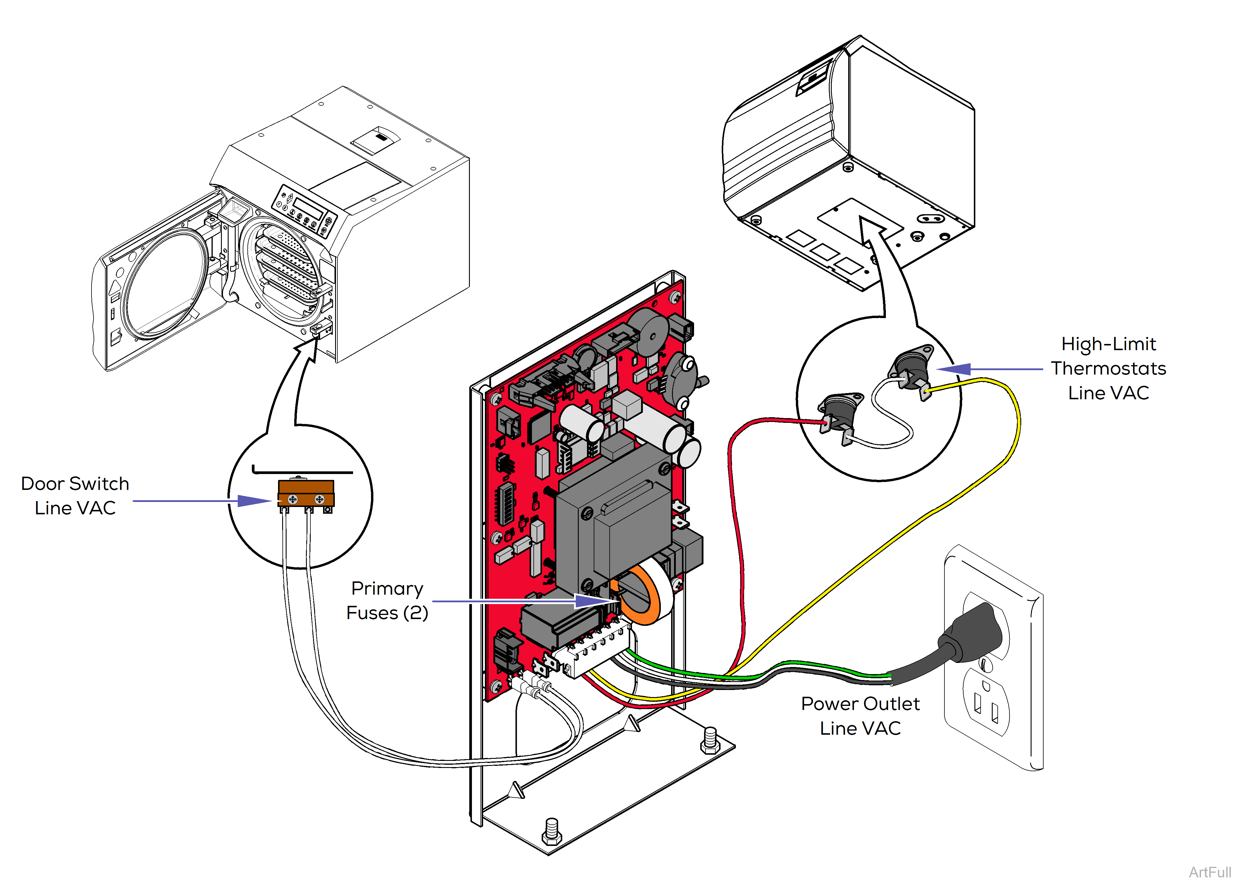
With the sterilizer’s power cord properly connected, facility supply voltage is supplied to the Main PC Board thru the two primary fuses.
If either fuse is faulty, the sterilizer will have no power.
When power is supplied to the Main PC Board, current continuously flows thru the two normally closed High-Limit Thermostats. This circuit powers all line voltage components except Fan System.
If either thermostat opens for any reason (overheat or malfunction), the sterilizer will shut down until unit cools or thermostat is replaced.
Once a cycle is initiated, the Main PC Board continuously monitors the status of the Door Switch.
If an open door is detected, the cycle will not start. If the door switch opens during a cycle, the cycle will be terminated and the corresponding error code will appear in the display.
