Midmark M9® -05x / M11® -05x Sterilizer Main PC Board Test and Repair
To prevent risk of shock always disconnect power before removing covers or performing any service procedure.
Some procedures require power to be connected with covers removed. Line voltage is present. Use extreme caution to prevent electric shock.
|
Model |
M9 -050, -053 | M11 -050, -051, -053 |
| Serial Number | All | All |
VAC Test
For proper test point readings, meter leads need to penetrate PC board conformal coating.

1.Set meter to VAC.
2.Place meter probes on desired points and check reading.
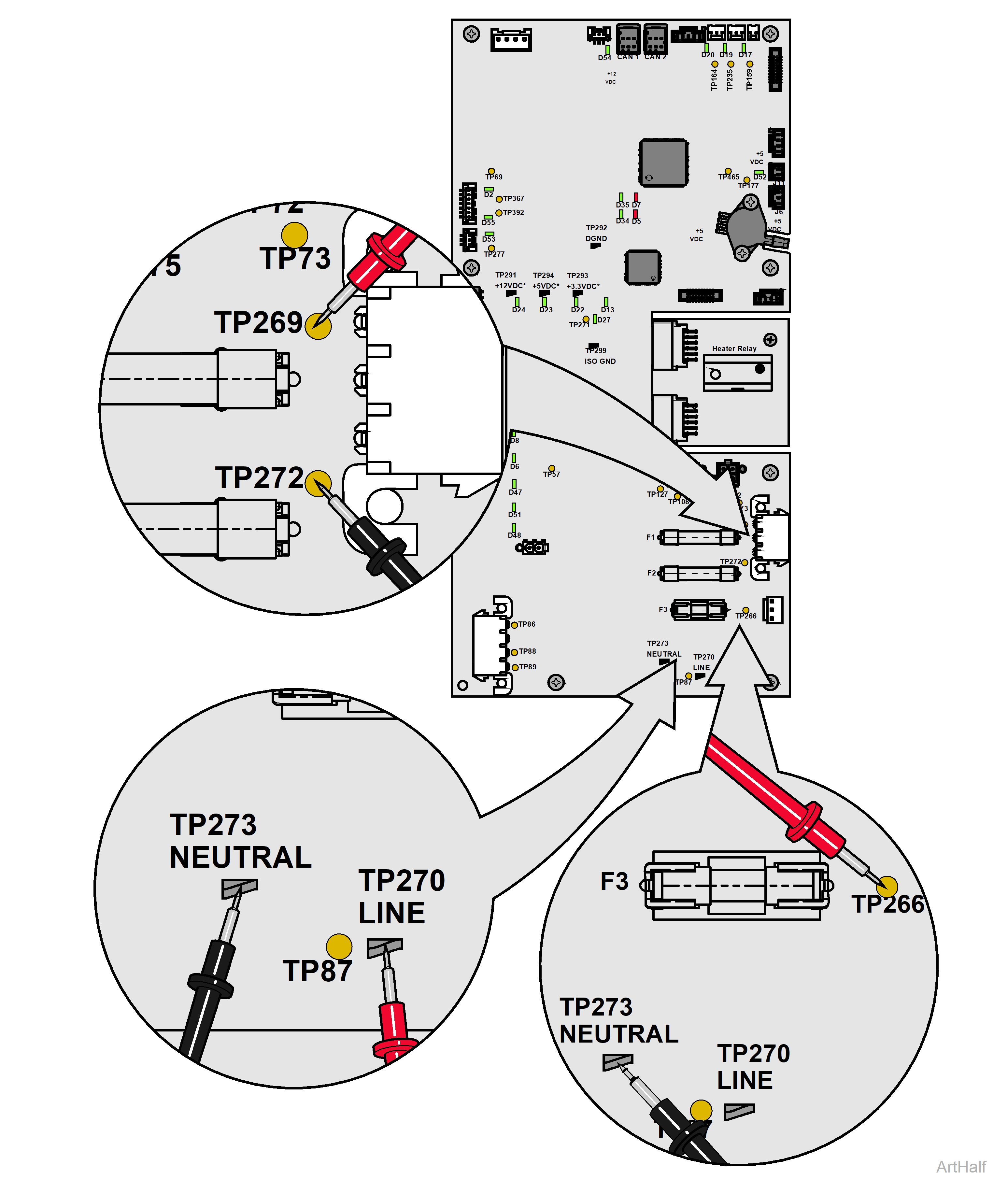
• AC line voltage in - Not Fused = TP269 and TP272
• AC line voltage in - Fused = TP270 and TP273
• AC out to power supply = TP266 and TP273
|
Meter Reading |
Required Action |
|---|---|
|
AC line voltage in - Not Fused (TP269 and TP272) = approximately 115 VAC / 230 VAC AC line voltage in - Fused (TP270 and TP273) = approximately 115 VAC / 230 VAC AC out to power supply (TP266 and TP273) = approximately 115 VAC / 230 VAC |
PC board is OK. |
|
AC line voltage in - Not Fused (TP269 and TP272) = approximately 0 VAC AC line voltage in - Fused (TP270 and TP273) = approximately 0 VAC AC out to power supply (TP266 and TP273) = approximately 0 VAC |
Check supply voltage. Check fuses. |
|
Any other reading |
Replace PC board. |
VDC Test
For proper test point readings, meter leads need to penetrate PC board conformal coating.

1.Set meter to VDC.
2.Place meter probes on desired points and check reading.
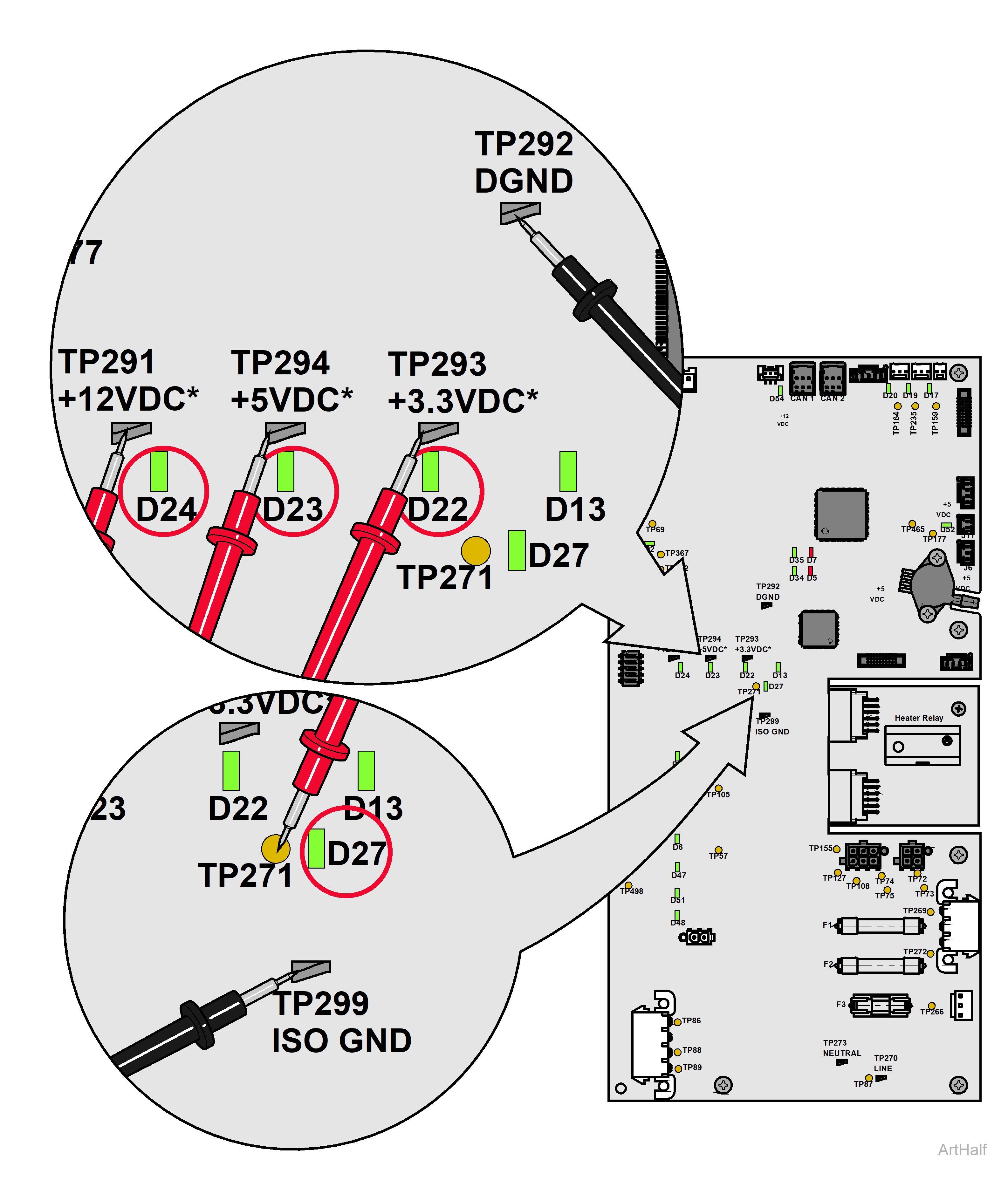
• 12V Net = TP291 and TP292
• 5V Net = TP294 and TP292
• 3.3V Net = TP293 and TP292
• 12V Isolated = TP271 and TP299
3.When voltage is present, the corresponding LED should light up.
• 12V Net = D24
• 5V Net = D23
• 3.3V Net = D22
• 12V Isolated = D27
|
Meter Reading |
Required Action |
|---|---|
|
12V Net (TP291 and TP292) = approximately 12 VDC 5V Net (TP294 and TP292) = approximately 5 VDC 3.3V Net (TP293 and TP292) = approximately 3.3VDC 12V Isolated (TP271 and TP299) = approximately 12 VDC |
PC board is OK. |
|
If VDC reading is low, investigate these items to determine if functioning properly prior to replacing PC board: Door Motor, Hall Effect Sensor, Door Dry Position Switch, CAN to Display, Fans, Water Level Sensor, Steam Temp Sensor, Auto Fill Accessory. |
Replace component. |
|
Any other reading |
Replace PC board. |

1.Set meter to VDC.
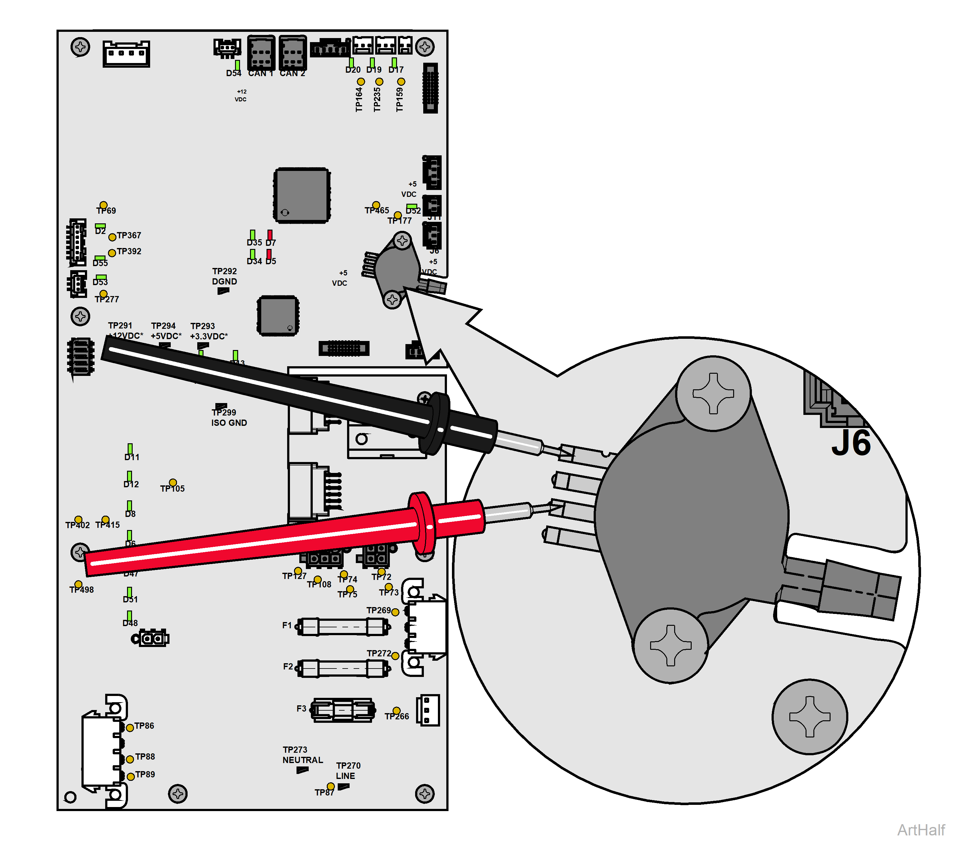
2.Place meter probes on transducer pins 1 and 3* (as shown in the figure above).
Pin position is referenced top to bottom (top pin = 1, bottom pin = 4).
|
Meter Reading |
Required Action |
|---|---|
|
Approximately 5 VDC |
PC board is OK. |
|
Any other reading |
Replace PC board. |

