Midmark M9® -05x / M11® -05x Sterilizer Water Level Sensor Test and Repair
To prevent risk of shock always disconnect power before removing covers or performing any service procedure.
|
Model |
M9 -050, -053 | M11 -050, -051, -053 |
| Serial Number | All | All |
Some procedures require power to be connected with covers removed. Line voltage is present. Use extreme caution to prevent electric shock.

1.Set meter to VDC.
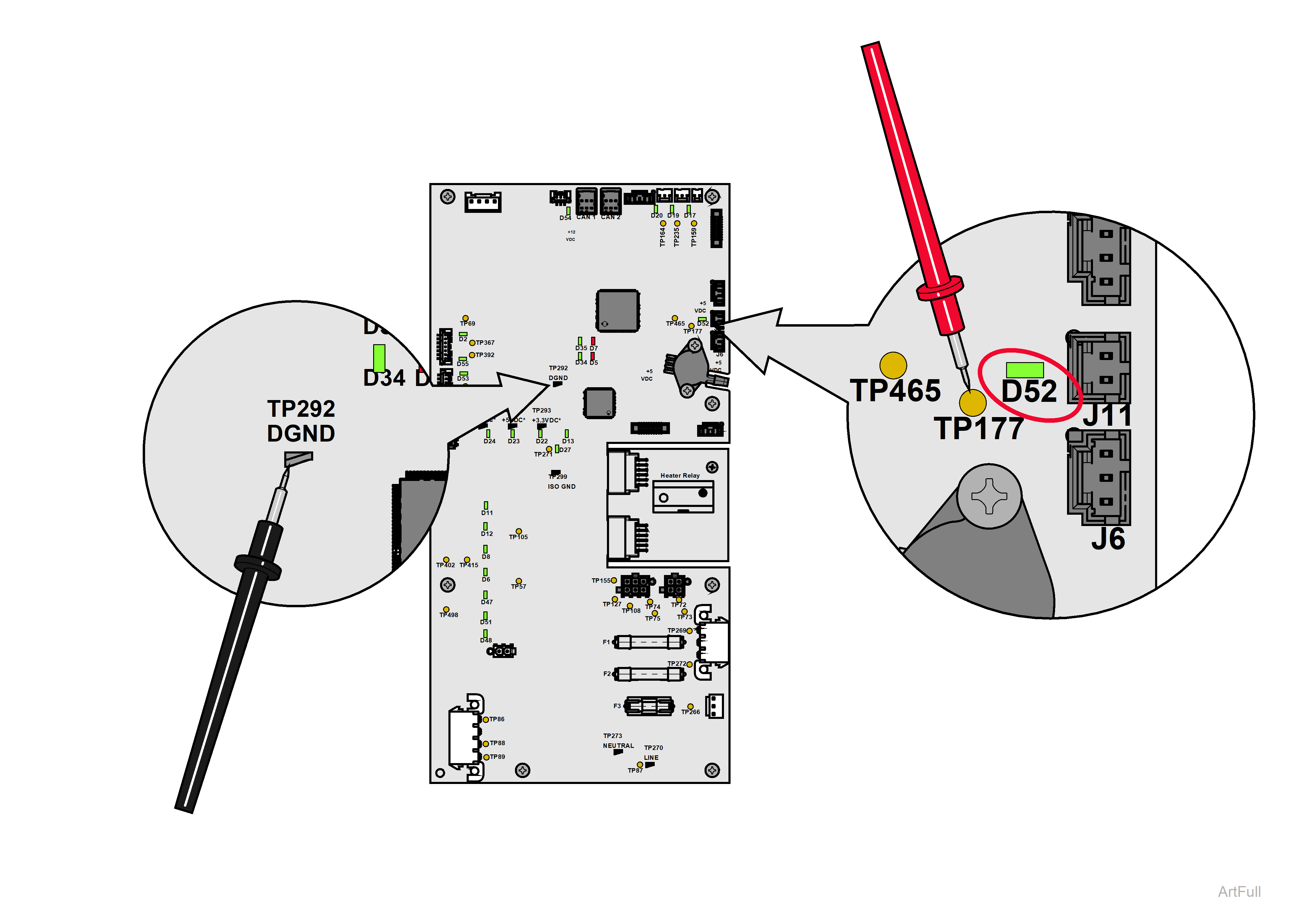
2.Place meter probes on points TP177 and TP292 (as shown in the figure above).
3.Activate the water level sensor by filling chamber with water up to the sensor and check reading.
LED D52 should light up.
|
Meter Reading |
Required Action |
|---|---|
|
No water touching sensor = approximately 3.3 VDC Water touching sensor = approximately 0 VDC |
PC board is OK. Sensor is OK. System functioning as expected, no further action required. |
|
No water touching sensor = approximately 3.3VDC Water touching sensor = approximately 3.3VDC |
Perform Ground Connection Test. |
|
Any other reading |
Replace PC board. |
Some procedures require power to be connected with covers removed. Line voltage is present. Use extreme caution to prevent electric shock.

1.Disconnect power from product.
2.Set meter to measure resistance.
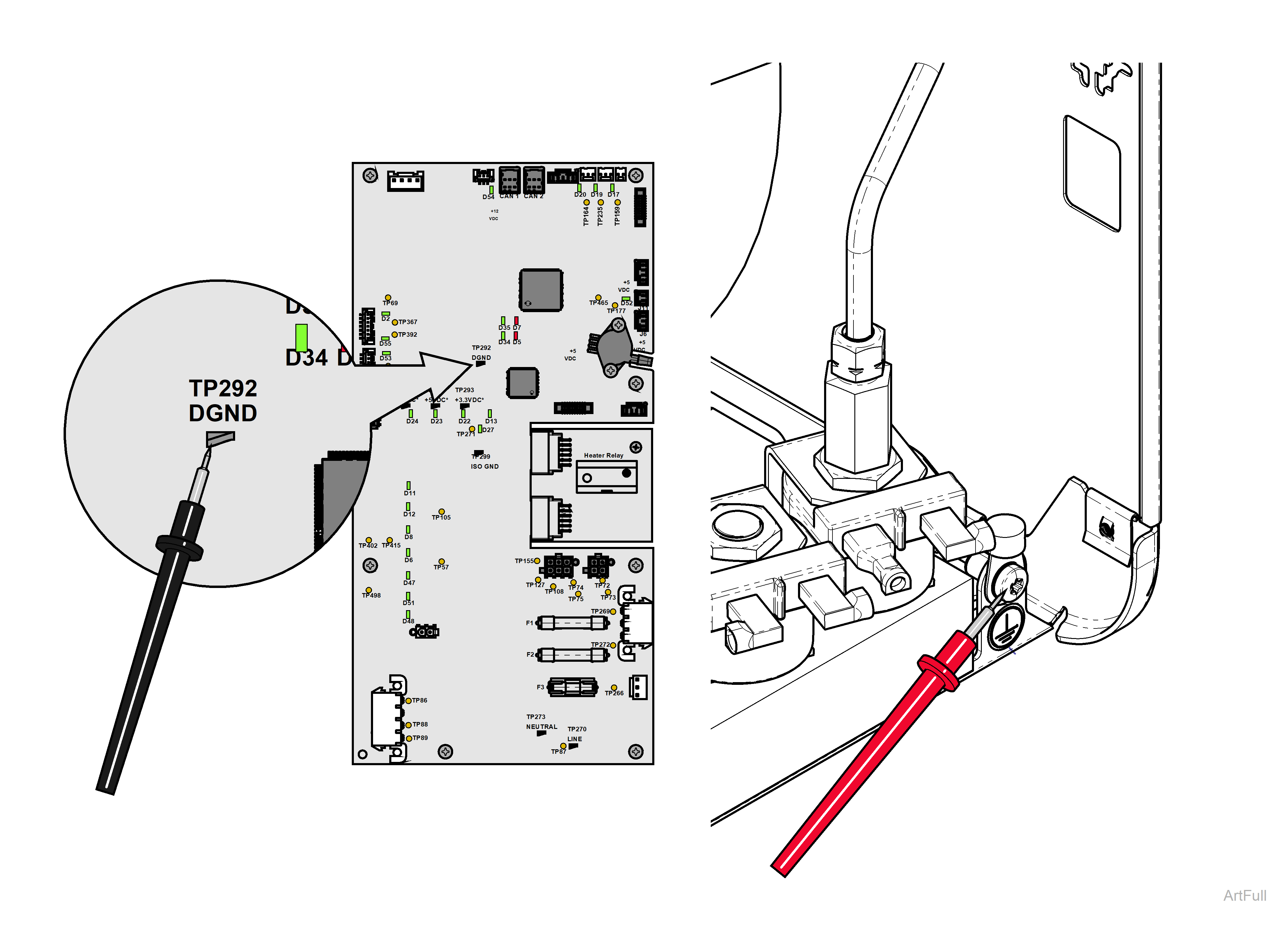
3.Place one meter probe on TP292 and one meter probe on the chassis ground connection on the base (as shown in figure above).
|
Meter Reading |
Required Action |
|---|---|
|
Resistance measures less than 10 ohms. |
PC board is OK. Perform Continuity Test. |
|
Resistance measures greater than 10 ohms. |
PC Board is damaged Proceed to Pinched /Cut Wires test Do not replace PC Board until after performing Pinched /Cut Wires test. |
Some procedures require power to be connected with covers removed. Line voltage is present. Use extreme caution to prevent electric shock.

1.Apply power to product.
2.Set meter to measure VDC.
3.Place red meter probe on the chassis ground connection on the base and black meter probe on TP292 on the PC board (as shown in figure above).
|
Meter Reading |
Required Action |
|---|---|
|
Voltage reading is approximately 12VDC. |
Checked for pinched or cut wires in the following locations: -Door motor wires. -Door motor supply wire harness. -12VDC power supply wire harness. -Fan wires. If a pinched or cut wire is found to be contacting the metal surface of the product, replace the affected component. After fixing pinched/cut wire, replace PC Board. |
|
Voltage reading is approximately 0VDC. |
No pinched/cut wires identified. Replace PC Board. |
Sterilizer or components may be hot or become hot. Wait until the sterilizer or components are cool to the touch before continuing service.

Resistance Test
1.Empty any water from chamber and dry sensor.
2.Disconnect wire from sensor terminal.
3.Set meter to Ohms (Ω).
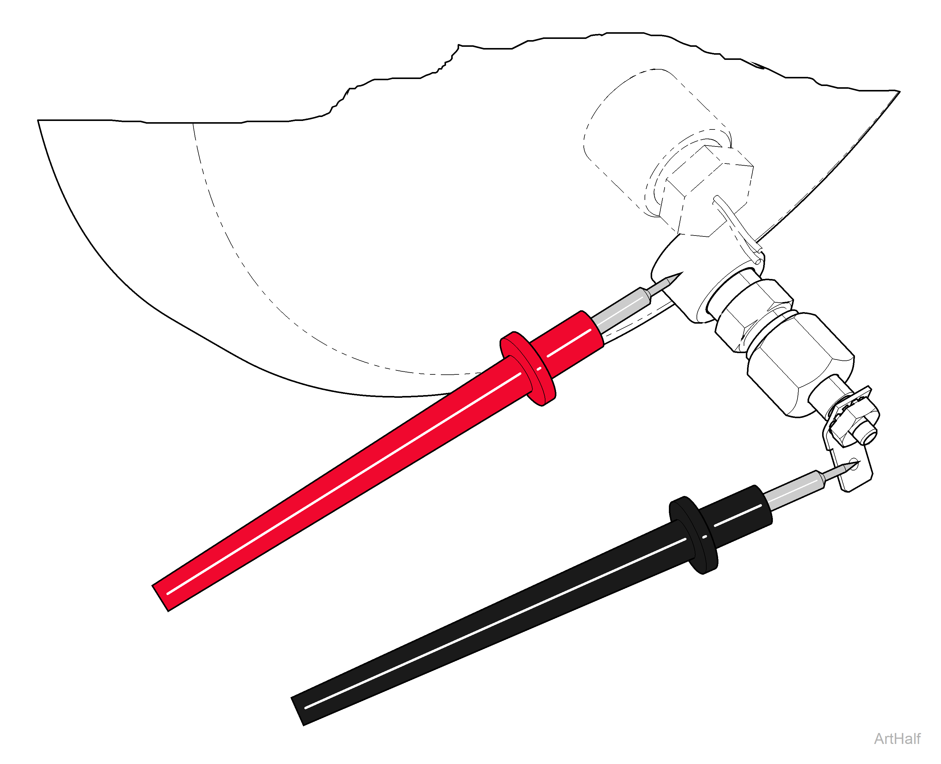
4.Place one meter probe on sensor terminal and the other probe on the chamber wall (as shown in the figure above).
Residue buildup on the sensor disk can cause malfunctions during the Filling mode. Clean the sensor disk with Speed-Clean and an abrasive pad; then dry disk thoroughly.
|
Meter Reading |
Required Action |
|---|---|
|
OL |
Water level sensor is good. |
|
Any reading other than OL |
Replace water level sensor. |

