244 Table Power To The Table Troubleshooting
Facility Supply Voltage
With the table's power cord properly connected, facility supply voltage 115 VAC is supplied thru the cord to the power inlet.
Power Inlet (Power Switch and Fuses)
Current flows thru two fuses in the power inlet to the power switch. When the power switch is turned ON (I), current flows to the control box.
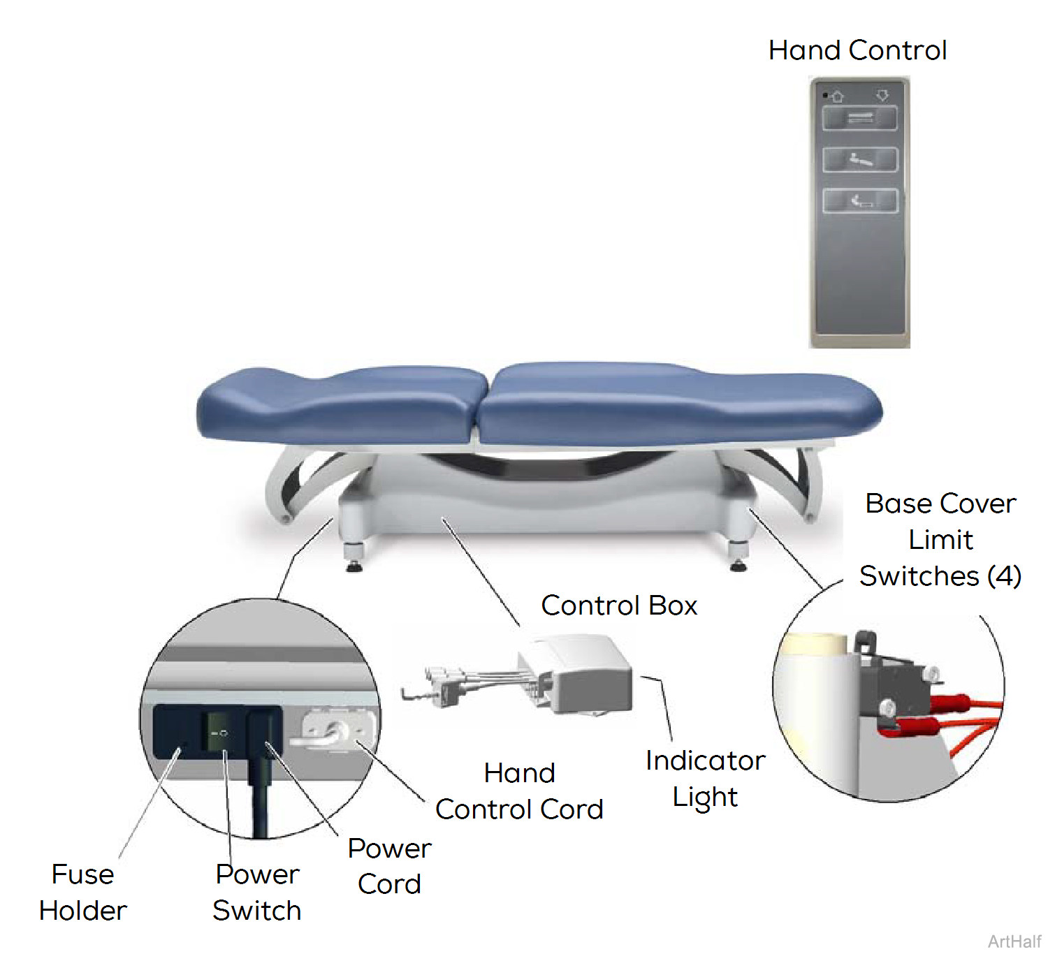
Control Box
115 VAC Line voltage is supplied to the control box thru the power inlet. An indicator light on the control box illuminates when power is present. The control box reduces the voltage and supplies approximately 5 VDC to the base cover limit switch circuit.
Base Cover Limit Switch Circuit
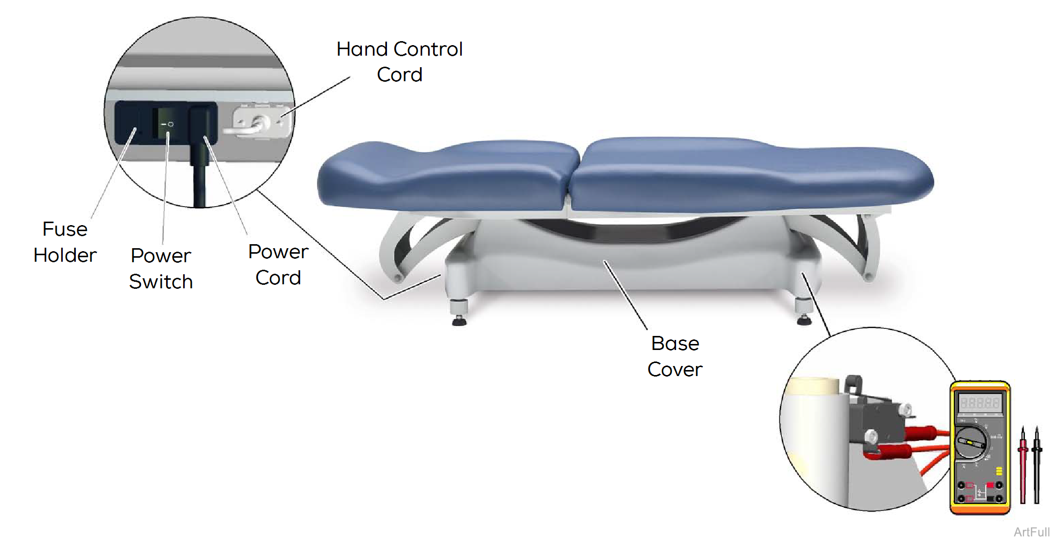
The base cover limit switches prevent injury and/or equipment damage by disabling all table functions if any pressure is applied to the base cover.
The control box supplies approximately 5 VDC to the four base cover limit switches. During normal operating conditions, current flows thru all four normally-closed switches, then to the hand control.
If pressure is applied to the spring-loaded base cover, one or more of the limit switches will be tripped. When any of the limit switches are tripped, there is no current supplied to the hand control.
Hand Control
With the hand control cord properly connected, 5 VDC is supplied to the hand control thru the four base cover limit switches. This current continuously flows back to the control box thru separate wires for each table function. When a function is selected from the hand control, this "signal voltage" is removed from the wire corresponding to the selected function. When the signal voltage is removed, the control box activates the selected function.
1.Is there power to the table? Power switch must be turned ON (I). Check facility circuit breaker.
2.Is there pressure / weight on the base cover? Any pressure on the base cover will disable all table functions.
3.Fuses (2)
4.Loose / Damaged Wire Connections. Check power cord and hand control cord.
5.Perform Limit Switch Circuit Test.
The power cord must be plugged in, and the power switch must be ON (I) during these tests.
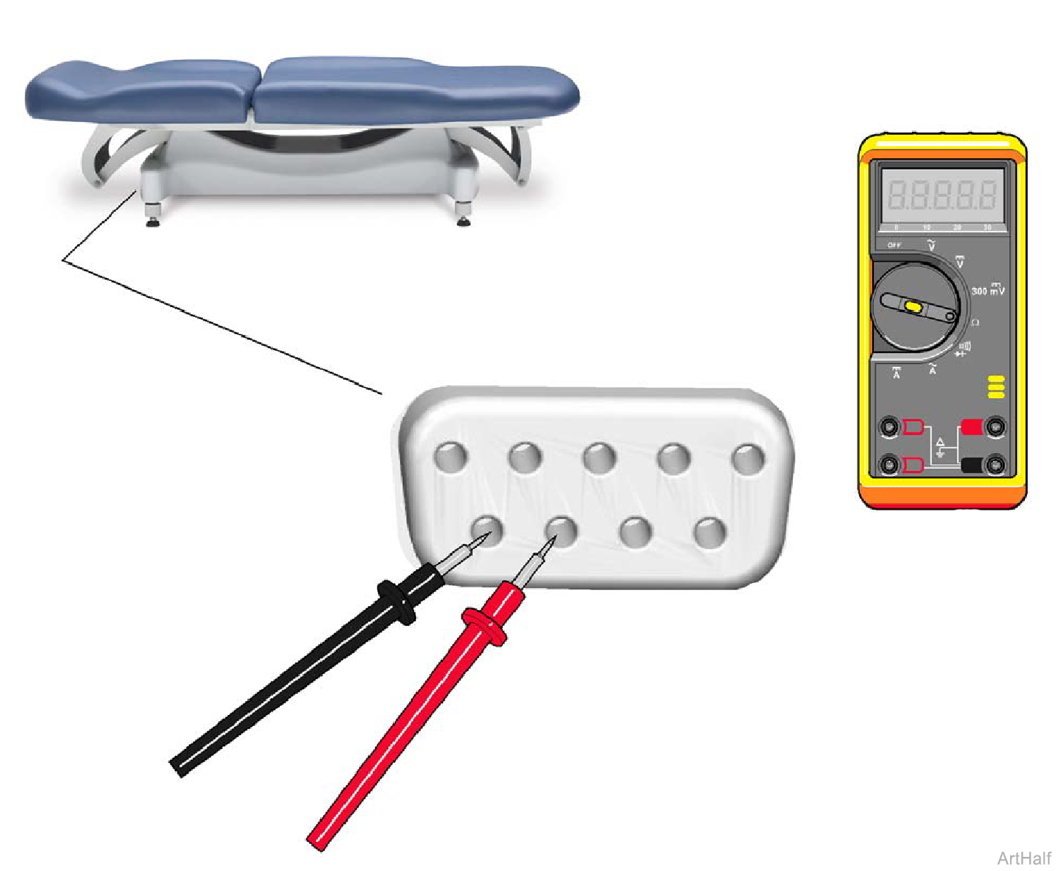
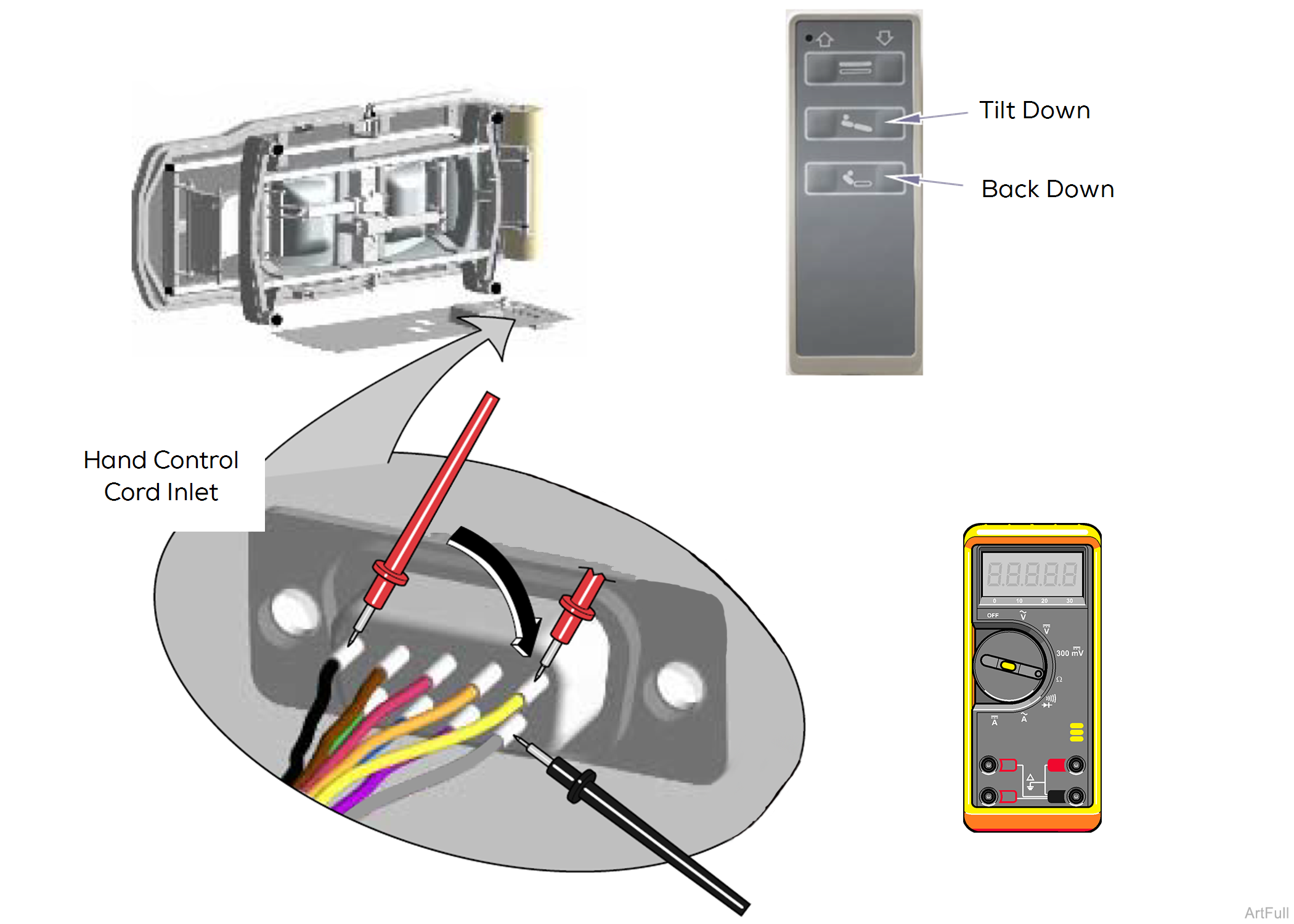
1.Unplug hand control cord from table.
2.Set meter to read DC voltage.
3.Insert meter probes exactly as shown into hand control inlet on table.
| Meter Reading | Required Action |
|---|---|
| Approximately 5 VDC | Limit Switch Circuit OK - includes fuses and power switch. Perform Signal Voltage Test #1. |
| 0 VDC | Limit Switch Circuit is malfunctioning. Perform Supply Voltage Test. |
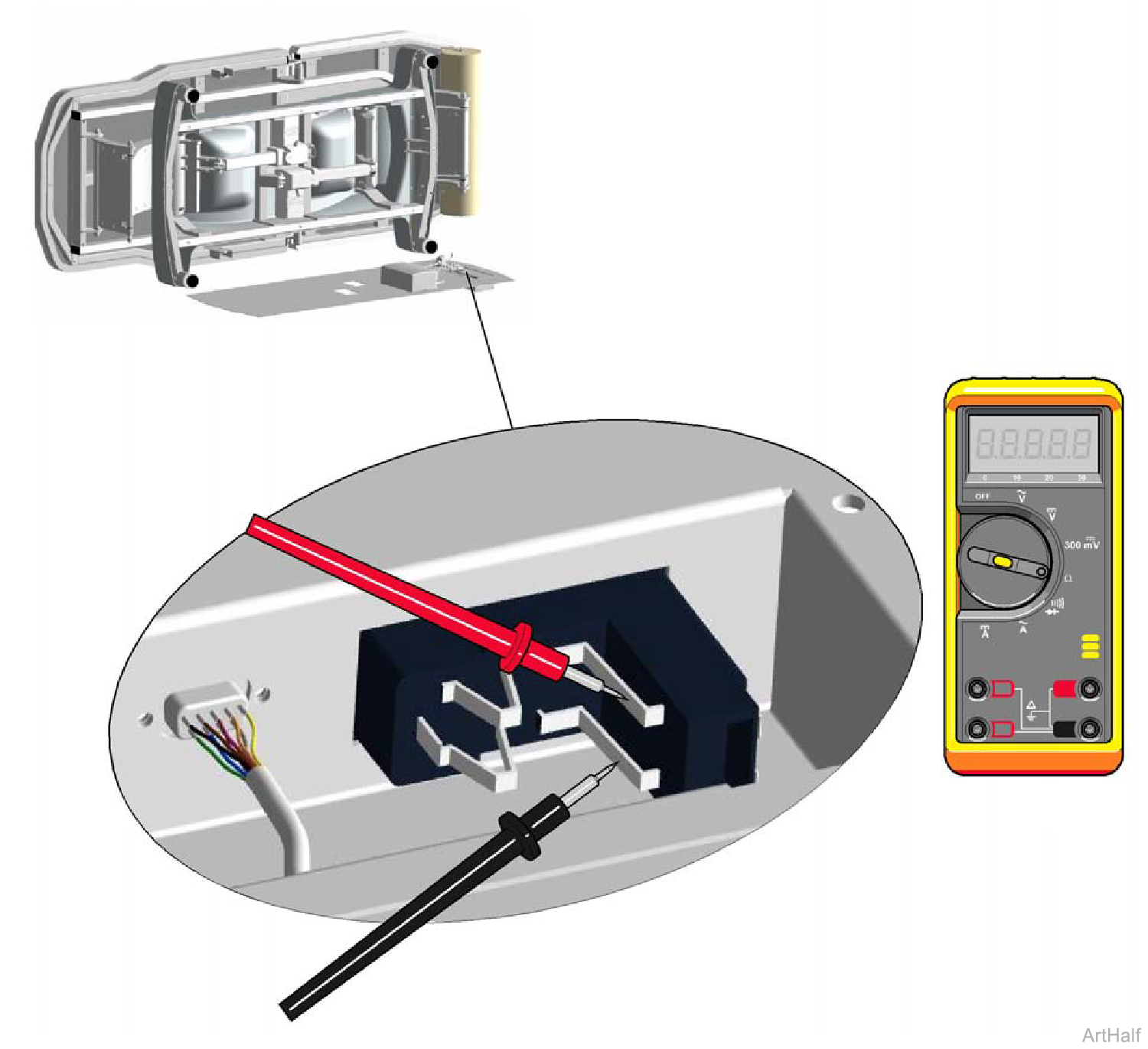
1.Remove bottom cover. Remove power inlet housing cover.
2.Set meter to read AC voltage.
3.Place meter probes on power switch terminals exactly as shown.
| Meter Reading | Required Action |
|---|---|
| Approximately 120 VAC |
Fuses and Power Inlet OK. Test all four Base Cover Limit Switches. Replace any faulty limit switch(es). If all limit switches are OK Inspect hand control port harness. Replace if damaged. If hand control harness is OK, replace control box. |
| 0 VAC |
Power supply problem. Check and replace faulty fuse(s). If fuses are OK, replace power inlet. |
Meter should indicate approximately 5 VDC, when hand control button is released. If not, perform Limit Switch Circuit Test.
1.Remove bottom cover and power inlet housing cover.
2.Set meter to read DC voltage.
3.Place black probe on GREY wire (common).
When specified hand control button is pressed, does voltage drop to approx. 0.7 VDC? If Yes, replace control box. If No, replace hand control.
4.Place red probe on Black wire. Press Tilt Down button on hand control. Check meter as button is pressed and released.
5.Move red probe to Yellow wire. Press Back Down button on hand control. Check meter as button is pressed and released.
