244 Table Lower Actuators Test and Repair
Under normal operating conditions, the hand control continuously supplies 5 VDC to the control box thru separate wires for each table function. When a function is selected from the hand control, this "signal voltage" is removed from the wire corresponding to the selected function.
When the signal voltage is removed, the control box activates the selected function and supplies 24 VDC to the appropriate actuator(s).
Both actuator motors run until
1.Hand control button is released.
2.Actuators reach their max./min. limits. Internal limit switches are not serviceable.
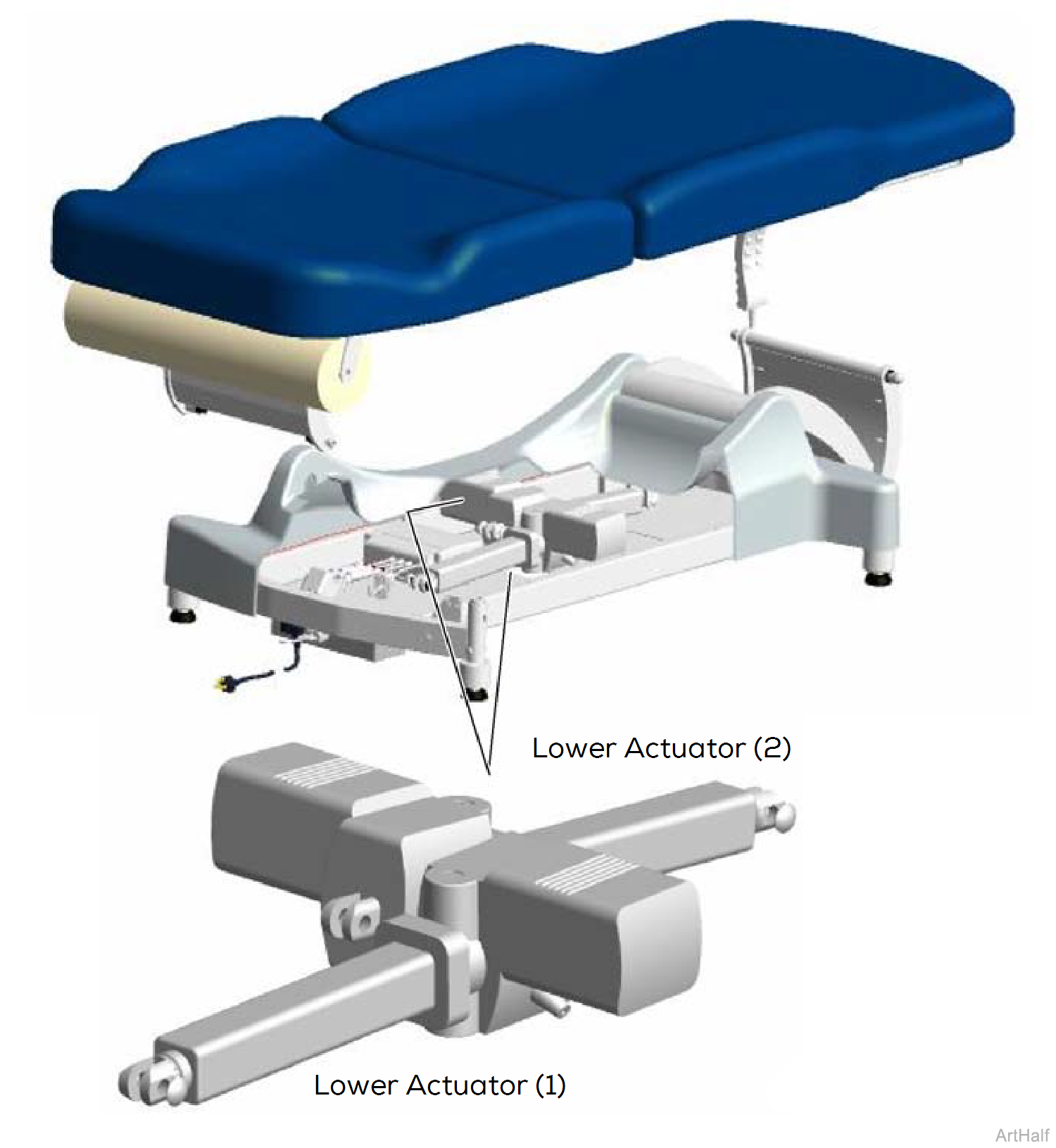
The lower actuators work in conjunction with each other to achieve the selected function.
| Function | Action |
|---|---|
| Base Up | Both lower actuators extend |
| Base Down | Both lower actuators retract |
| Tilt Up |
Lower actuator (1) retracts Lower actuator (2) extends |
| Tilt Down: |
Lower actuator (1) extends Lower actuator (2) retracts |
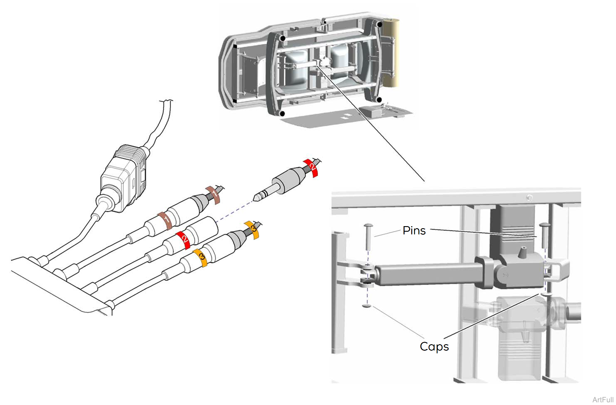
Removal
1.Disconnect power to table.
2.Remove bottom cover.
3.Disconnect actuator wire from control box wire.
4.Pry off two caps.
5.Remove two pins and actuator.
Installation
1.Position actuator.
2.Install two pins and caps.
3.Connect actuator wire to control box wire.
