244 Table Cover Access Procedures
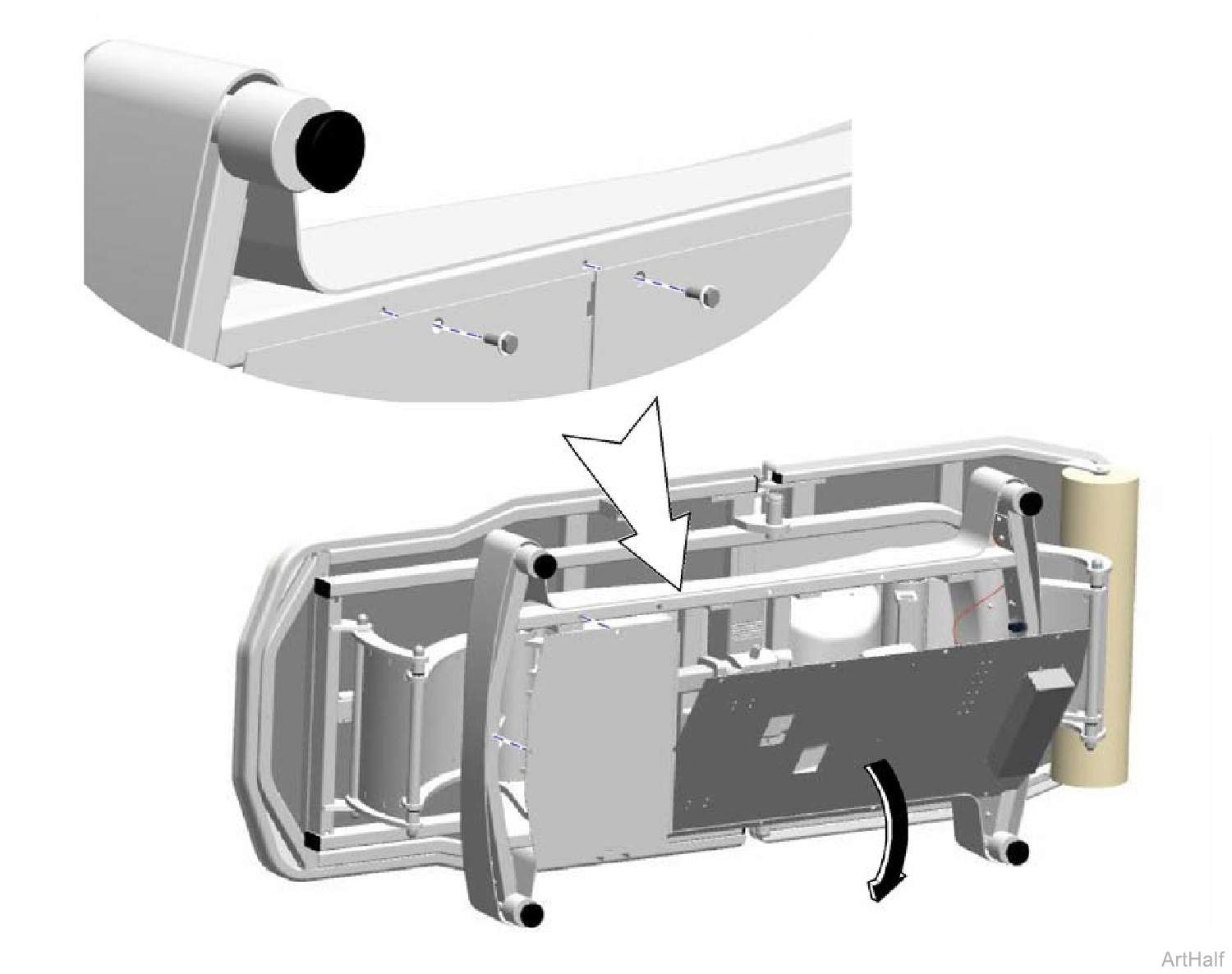
The table weighs 340 lbs (154 kg). Work with an assistant to move the table.
Removal
1.Remove seat and back upholstery.
2.Disconnect table power cord.
3.Work with an assistant to carefully lay the table onto its side.
Be careful not to damage wire connections when laying large cover down. Cut cable ties as necessary.
4.Remove screws from large cover and carefully lay cover down.
5.Remove screws and small cover.
Installation
1.Replace any cable ties cut during cover removal.
2.Hold cover(s) in position and secure with screws.
3.With the help of an assistant, stand table upright.
This procedure should only be performed when replacing the base cover. All components can be accessed by simply removing the bottom cover.
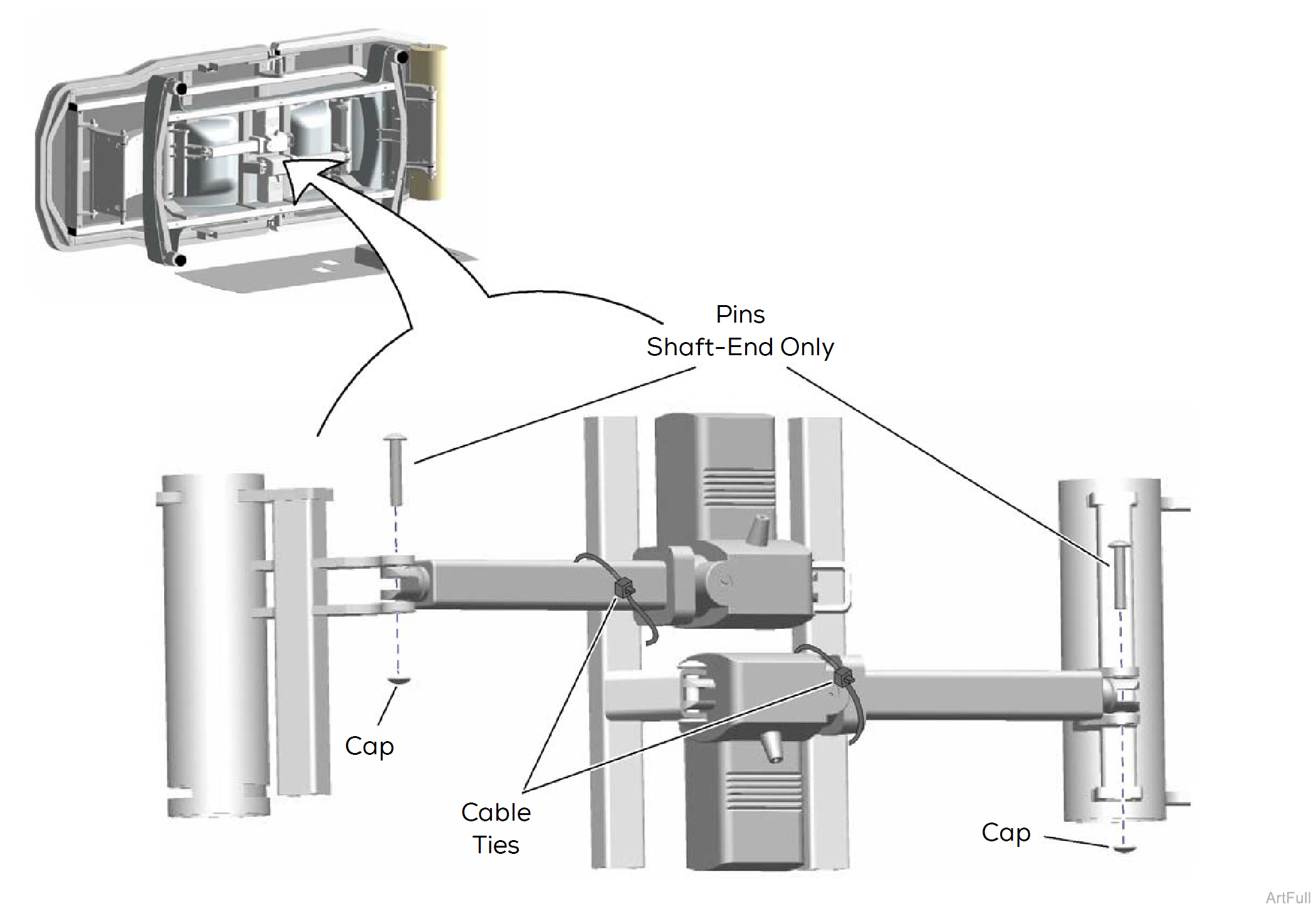
1.Remove bottom cover.
2.Secure both lower actuators to frame with cable ties.
3.Remove caps and pins from shaft end of both lower actuators.
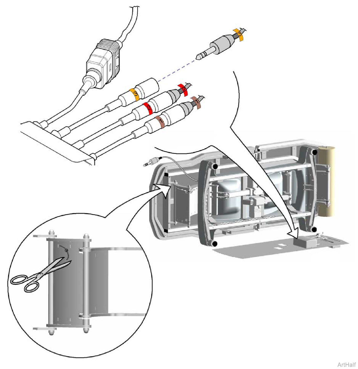
4.Disconnect wire harness extension (3) from control box wire (3).
5.Cut all wire ties securing the wire harness extension.
6.Pull harness extension up thru base cover.
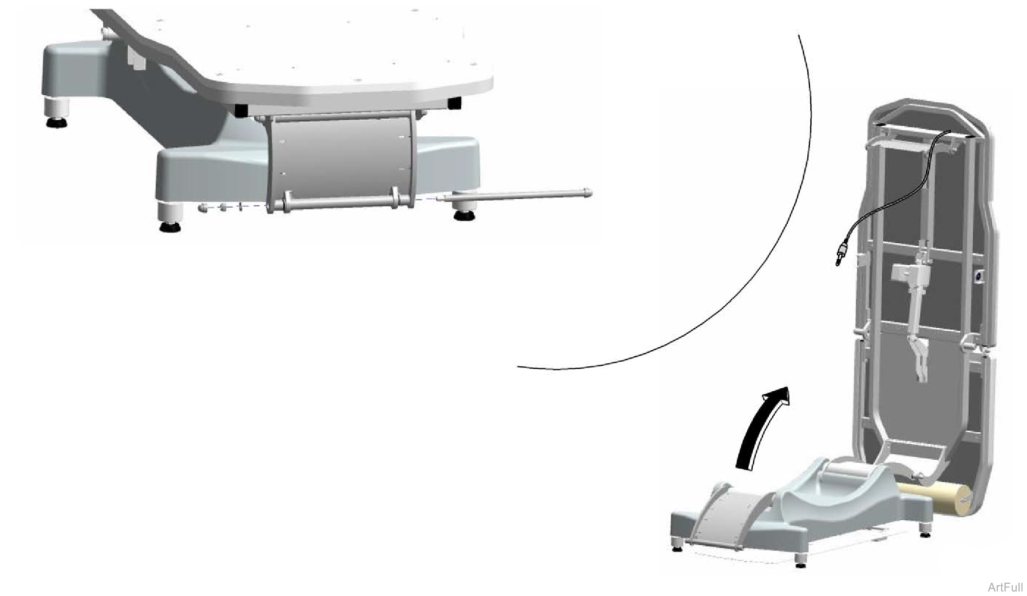
7.Carefully stand table upright.
8.Remove cap, nut, and washer.
9.Using a rubber mallet and/or a wooden dowel, drive pivot bar out of weldment.
Work with an assistant to help secure table top when performing Steps 10 thru 13.
10.Carefully pivot table top toward head-end.
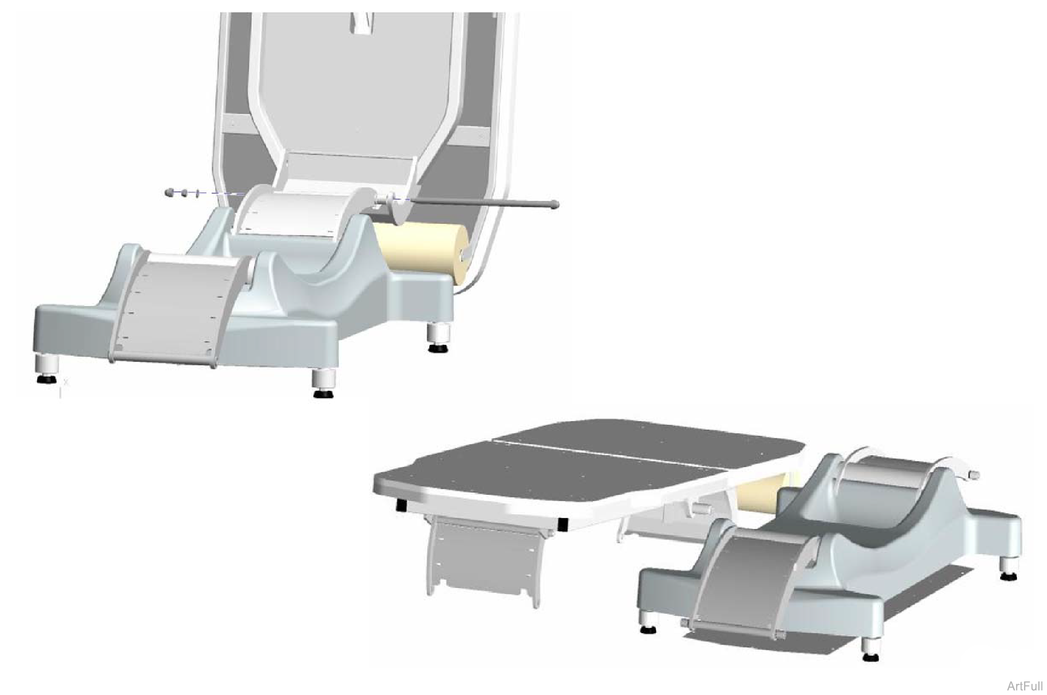
11.Remove cap, nut, and washer.
12.Using a rubber mallet and/or a wooden dowel, drive pivot bar out of weldment.
13.Carefully set table top aside.
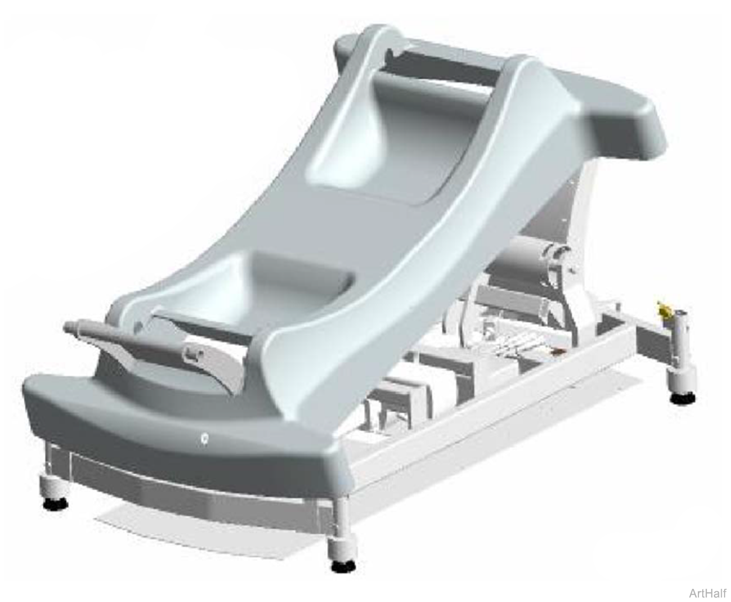
14.Lift cover over pivot weldments, one side at a time.

1.Install cover over pivot weldments, one side at a time.
Work with an assistant when performing Steps 2 thru 5.

2.Carefully stand table top upright and align frame with holes in pivot weldment.
3.Install pivot bar.
4.Install washer, nut, and cap.

5.Carefully lay table top down and align frame with holes in pivot weldment.
6.Install pivot bar.
7.Install washer, nut, and cap.

8.Carefully lay table onto its side.
9.Route wire harness extension to the control box. Replace all wire ties cut during Removal procedure.
10.Connect wire harness extension (3) to control box wire (3).

11.Cut cable ties securing lower actuators.
12.Secure both lower actuators with pins and caps.
13.Replace bottom cover.
|
Model |
244 |
| Serial Number | 045102845 thru 045102866 |
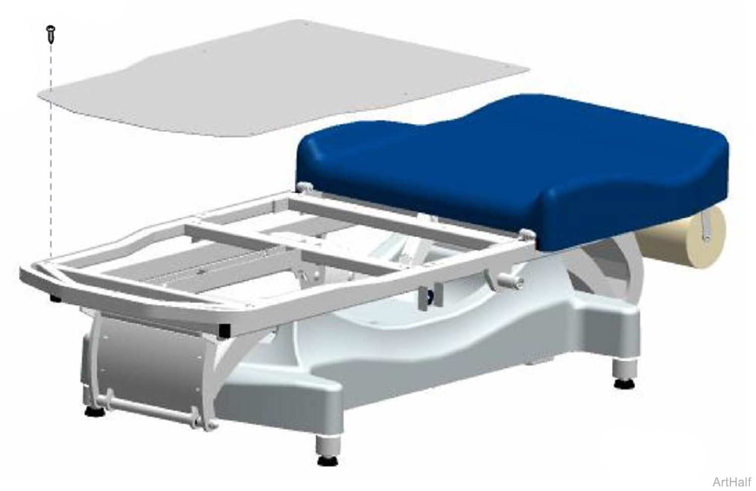
Removal
1.Remove seven screws.
2.Remove seat section cover.
Installation
1.Position seat section cover.
2.Install seven screws.

