625 Table Base Function Components Test and Repair
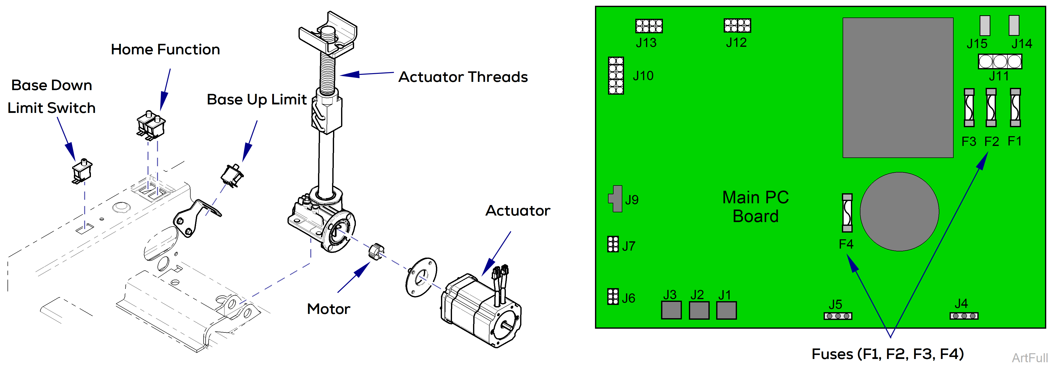
This illustration shows the base limit switches, the serviceable components of the base actuator, and the fuses on the main PC board. Use the table below to isolate the malfunction.
|
Problem |
Required Action |
|---|---|
|
Motor does not run. |
Check main PC board fuses (F1, F2, F3, and F4) |
|
Perform Limit Switch Test below. |
|
|
Base function operates, but makes grinding / squeaking noises |
Clean / lube actuator threads. Remove any debris from base slides. Do not lubricate base slides. Replace actuator if necessary* |
|
Motor runs, but table does not move. |
Inspect / replace motor coupler. |
*Replacement instructions are provided with the part. They are also available on midmark.com.
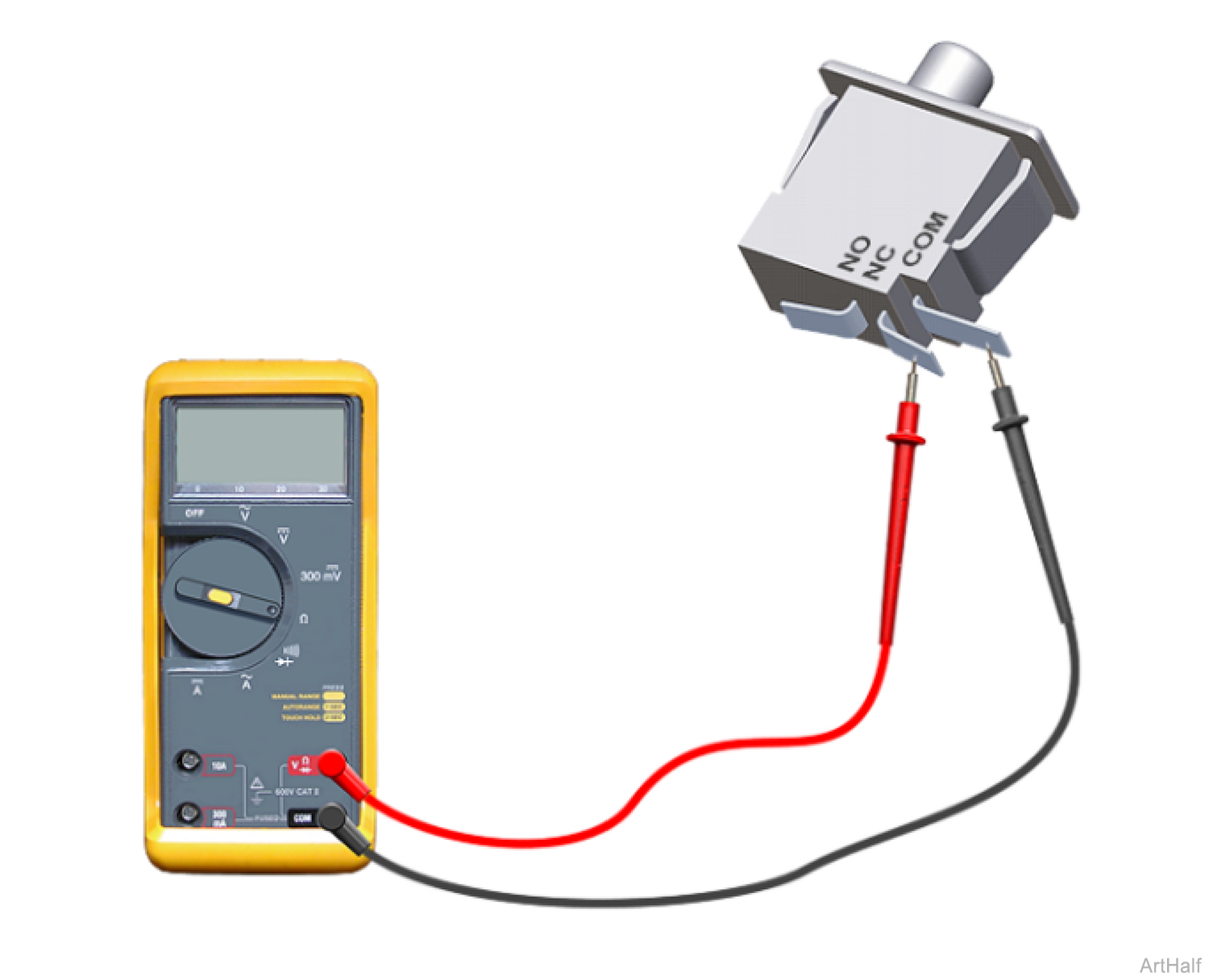
1.Disconnect wires from switch.
2.Place meter probes on COM and NC terminals.
Check switch Tripped and Untripped.
| With Switch Untripped | |
|---|---|
|
Meter Reading |
Required Action |
|
OL |
Replace limit switch |
|
less than 5 ohms |
Limit switch - OK Perform PC Board Test below. |
| With Switch Tripped | |
|---|---|
|
Meter Reading |
Required Action |
|
OL |
Limit switch - OK Perform PC Board Test below. |
|
less than 5 ohms |
Replace limit switch |
The back limit switches will not stop movement during this test. Do not run past max. / min. positions.
1.Move Back section so that it is approximately half way between its maximum and minimum positions.
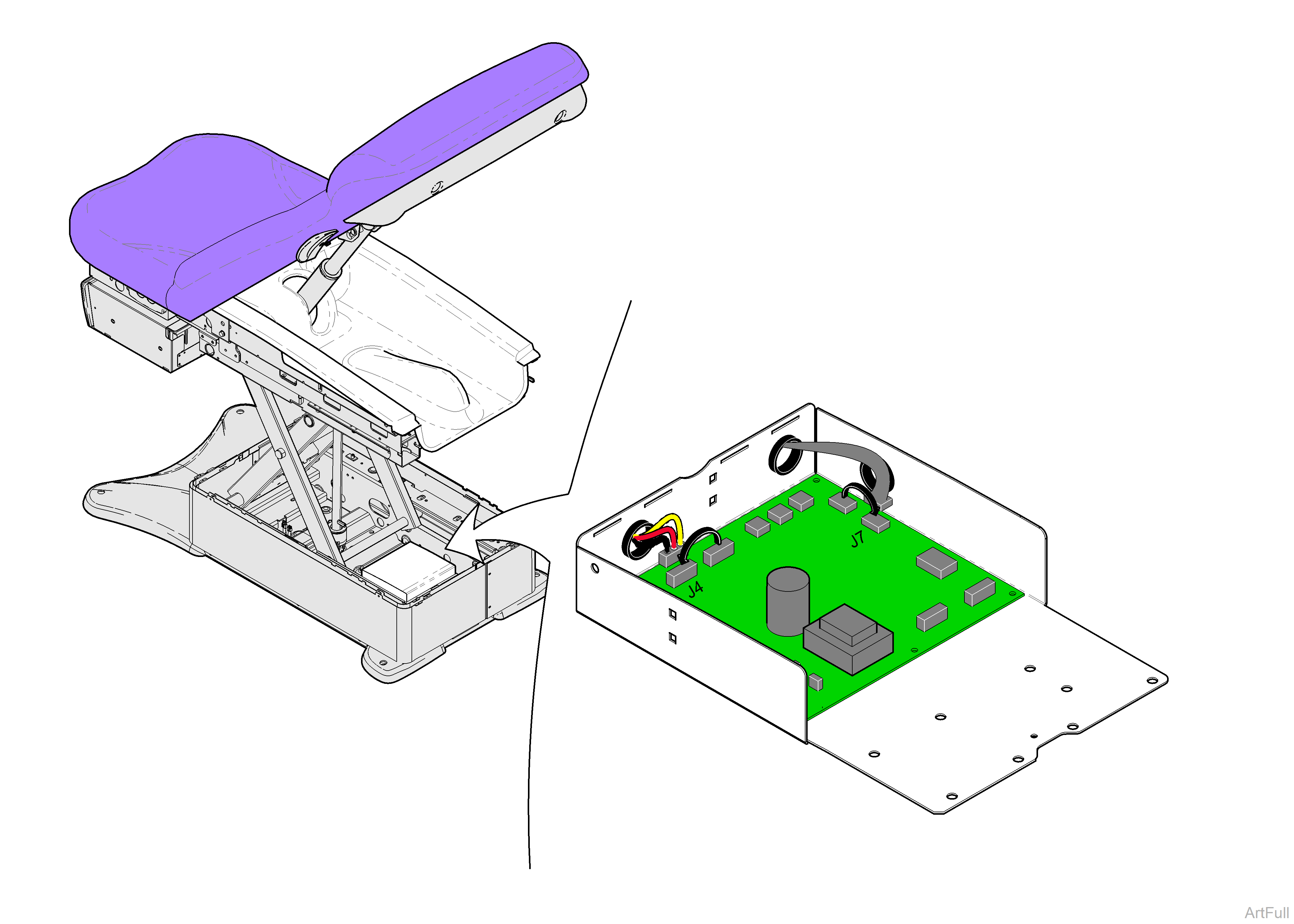
2.Tag, then disconnect back and base actuator wire connections at J4 and J5. Tag then disconnect back and base sensor wire connections at J6 and J7.
Failure to move both connections may result in damage to PC Board.
3.Move base actuator connection to J4 and base sensor connection to J7.
4.Using the hand / foot control, Press and hold BACK up briefly, then, press and hold BACK down briefly.
5.Calibrate PC Board.
|
Did Base move up and Down in Step 4? |
Required Action |
|---|---|
|
Yes |
Replace main PC board* |
|
No |
Refer to: Base Actuator Motor Resistance Test |
*Replacement instructions are provided with the part. They are also available on midmark.com.
