Canis Major Theory of Operation
|
Model |
CMDT-45 | CMDT-WS-45 | CMDT-60 | CMDT-WS-60 | CMDT-GC-60 |
| Serial Number | All | All | All | All | All |
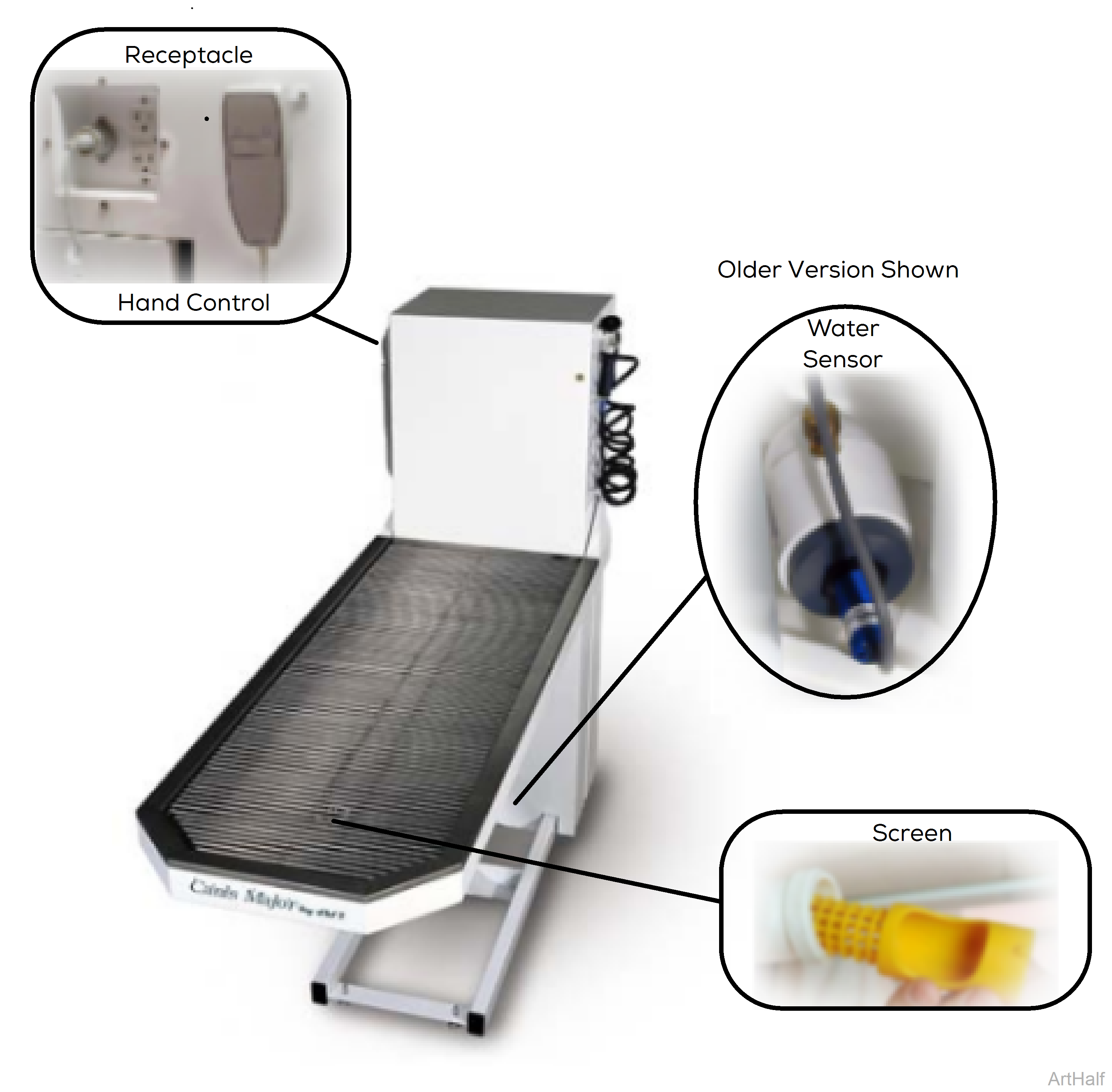
With the table's power cord properly connected, facility supply voltage (115 VAC) is supplied thru the cord to the GFI (Ground Fault Interruption) receptacle and into the electrical box. Current flows to the water sensor, pump, timer, power supply for scale (if applicable) and control box.
The control box reduces the voltage and supplies 24 VDC to the limit switch, hand control, actuator, and the timer in the electrical box.
The current in the hand control continuously flows back to the control box thru separate wires for table function. When a direction is selected from the hand control, this "signal voltage" is removed from the wire corresponding to the selected function. When the signal voltage is removed, the control box activates the actuator lifting the table up or down.
When the sprayer hand control is activated for water, it flows in through a hot and cold water intake connection. Hot and cold water flow together though a mixing valve which is factory set at 70° F (21°C) but can be adjusted up to 120° F (49°C). Mixed water then flows through to a shut-off valve and then on to the sprayer.
Water is collected in a stainless steel pan and drains through a screen and out the drain hose. Water flows down thru the drain hose and activates the water sensor which starts the pump. The water then travels through the pump and out into the drain. Whenever the water sensor senses water running past it the pump will be activated.
When the sensor no longer senses water, the timer is activated which keeps the pump running for 3 seconds and empties the table plumbing of water.
|
Model |
CMWO | CMWS |
| Serial Number | All | All |
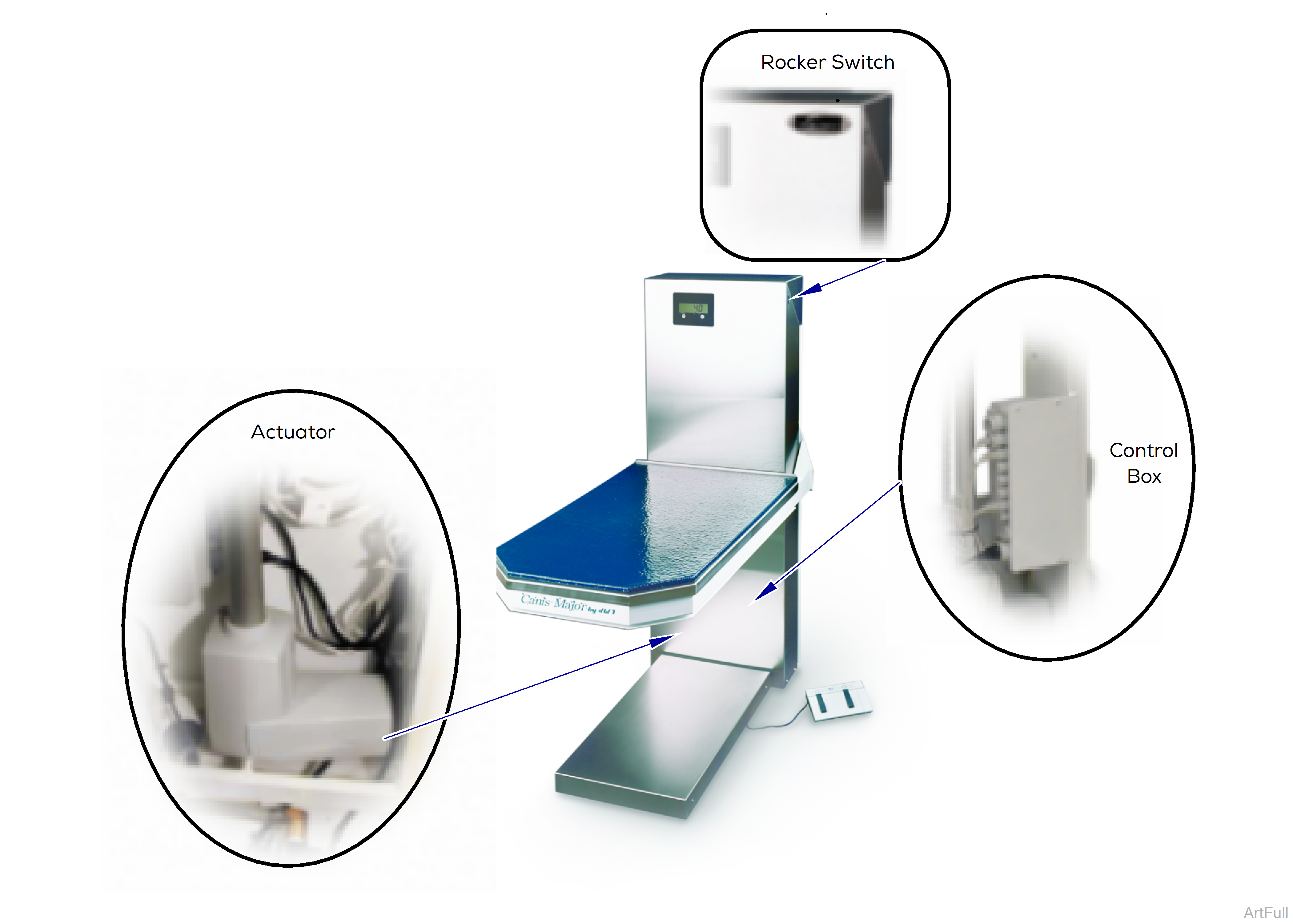
With the table's power cord properly connected, facility supply voltage (115 VAC) is supplied thru the cord to the receptacle for scale power supply (if applicable) and control box.
The control box reduces the voltage and supplies 24 VDC to the lift actuator and energizes the safety and rocker (up/down) switches.
The current in the rocker switches and foot control continuously flows back to the control box through separate wires for table raise and lower function. When a direction is selected and the rocker switch is activated, the "signal voltage" is interrupted from the wire corresponding to the selected function. When the signal voltage is interrupted, the control box activates the actuator moving the table either up or down.
The table has a safety pan directly beneath the table top. If an obstruction is encountered as the table top is descending the safety switches will activate and the table will stop. In this instance, the table will always rise when the up switch is activated, unless the table is in the full up position.
