646 Chair Tilt Actuator / Limit Switch / Sensor PC Board Test and Repair
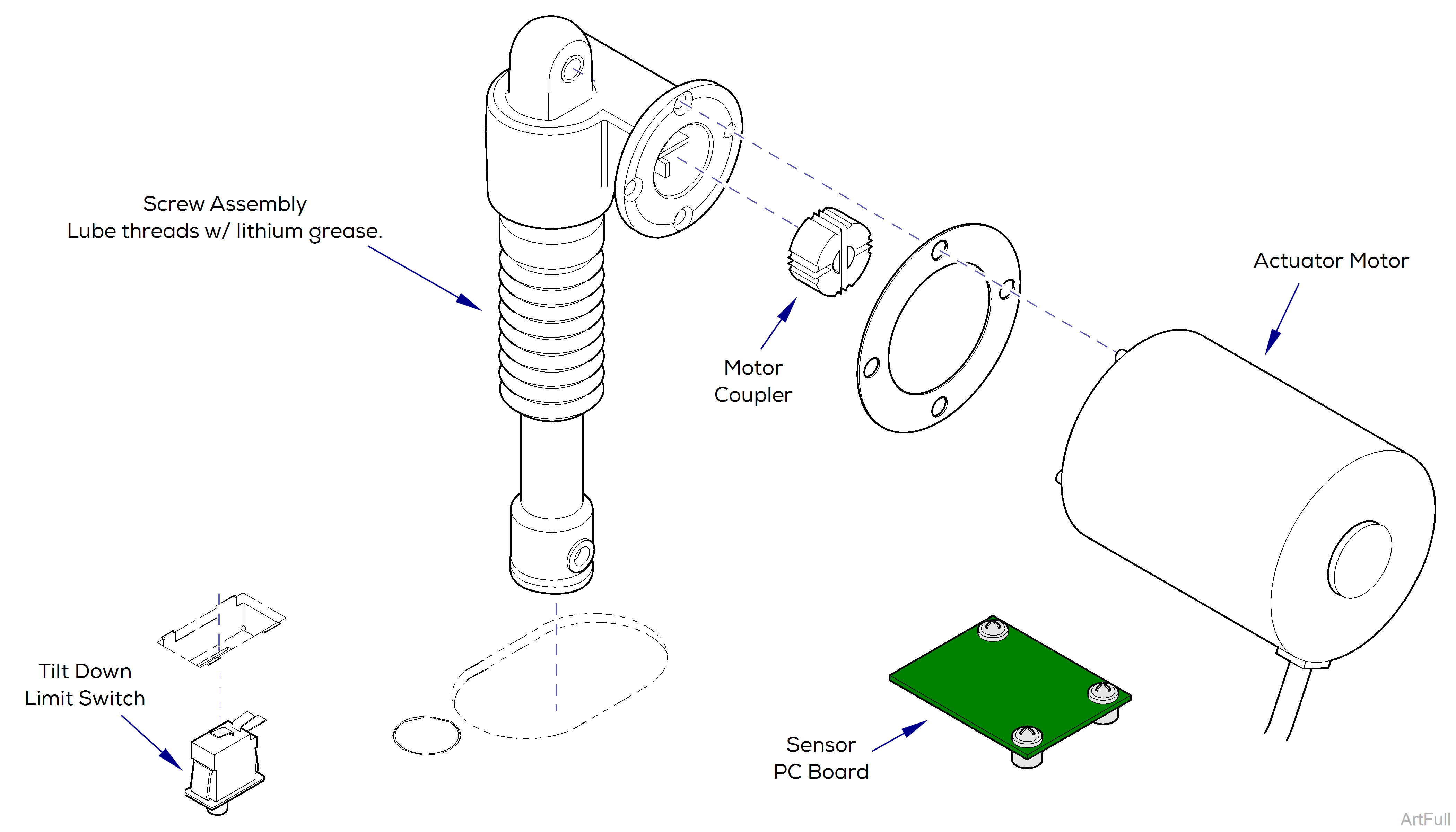
There is only one limit switch for the Tilt function.The upper limit is controlled by the Sensor PC Board.
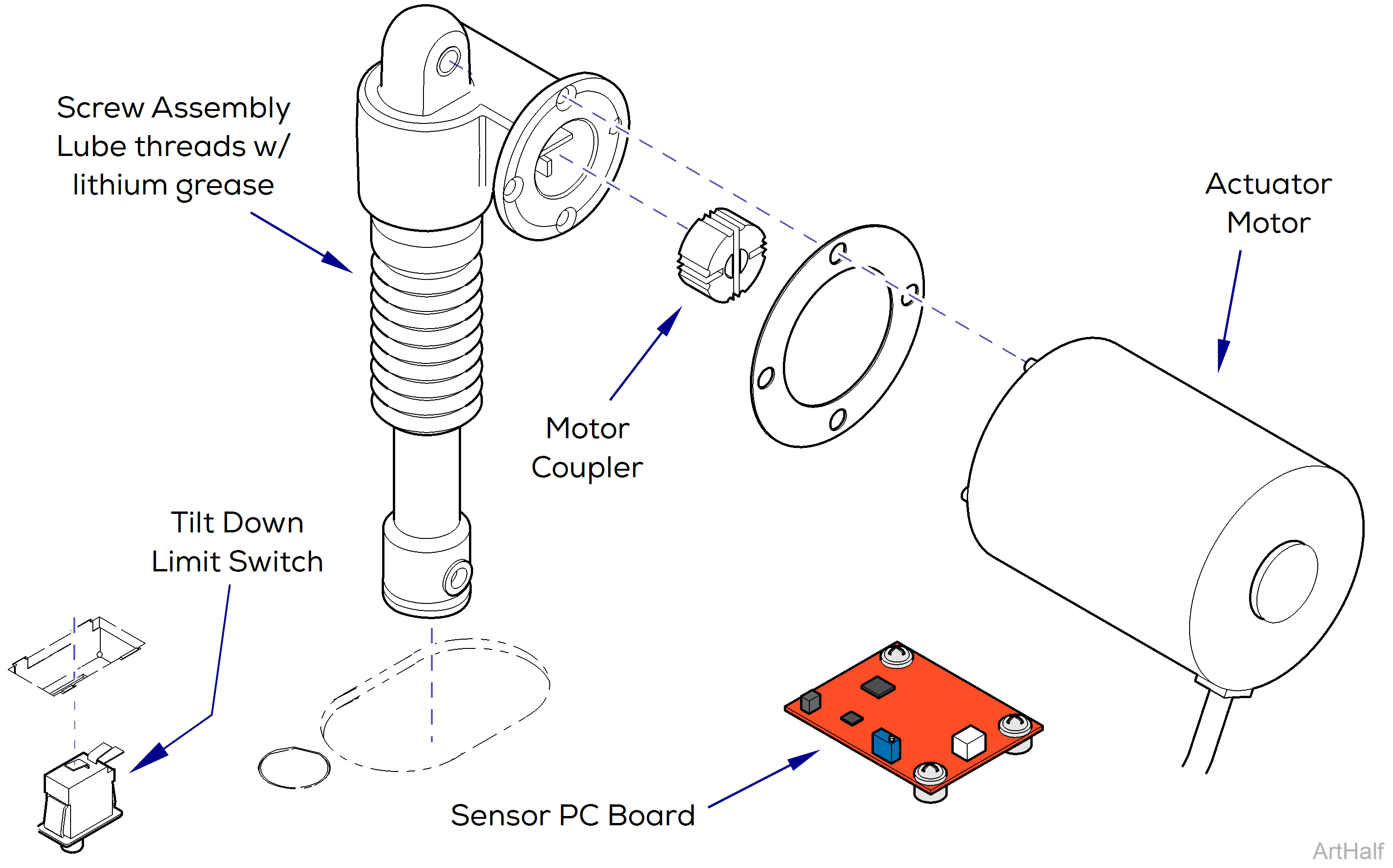
This illustration shows the tilt down limit switch, the sensor PC board, and the three serviceable components of the tilt actuator. Use the table below to isolate the malfunction.
|
Problem |
Required Action |
|---|---|
|
Tilt Up / Down OK, but beeps in full Up position. |
Perform Sensor PC board check |
|
Motor runs, but makes grinding noise. |
Clean / lube actuator threads. Replace actuator if necessary. |
|
Motor runs, but table does not move. |
Inspect / replace motor coupler. |
|
Motor does not run. |
Down only - Perform Limit Switch / PCB Harness Test |
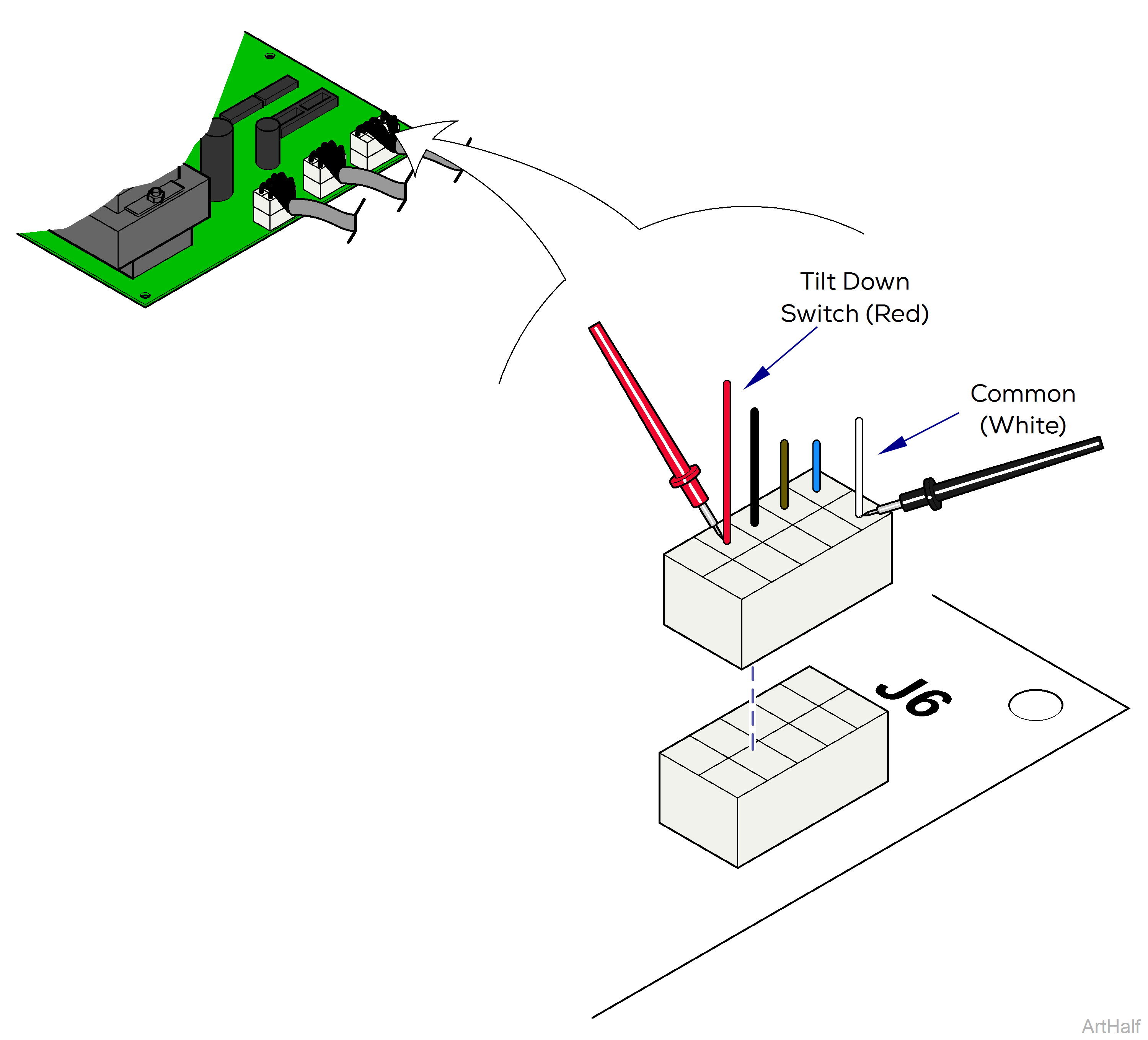
1.Disconnect harness from J6 on main PC board.
2.Place one meter probe on the common (white).
3.Place other probe on the red wire (see illustration).
Check switch tripped and untripped.
| With Tilt Down Switch Tripped | |
|---|---|
|
Meter Reading |
Required Action |
|
OL |
Limit switch / harness OK Perform Actuator Motor Test |
|
Less than 10 ohms |
Perform Limit Switch Harness Test |
| With Tilt Down Switch Untripped | |
|---|---|
|
Meter Reading |
Required Action |
|
OL |
Perform Limit Switch Harness Test |
|
Less than 10 ohms |
Limit switch / harness OK Perform Actuator Motor Test |
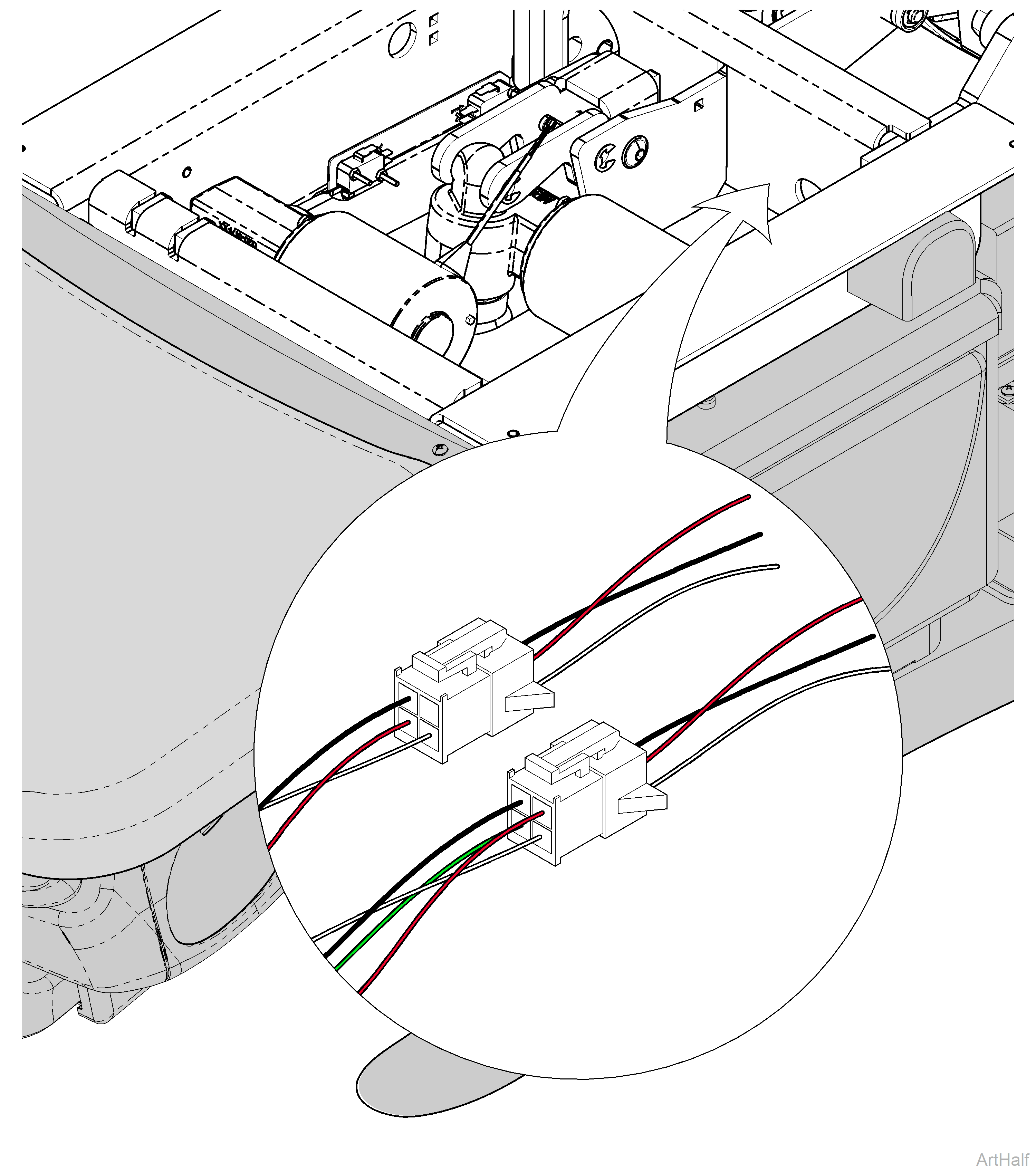
1.Unplug the appropriate limit switch harness.
2.Measure continuity.
|
Actuator Position |
Meter Reading Should Be |
|---|---|
|
Actuator Full Up |
White to Black - Open |
|
Actuator Full Down |
White to Black - Closed |
|
Actuator Midway Point |
White to Black - Closed |
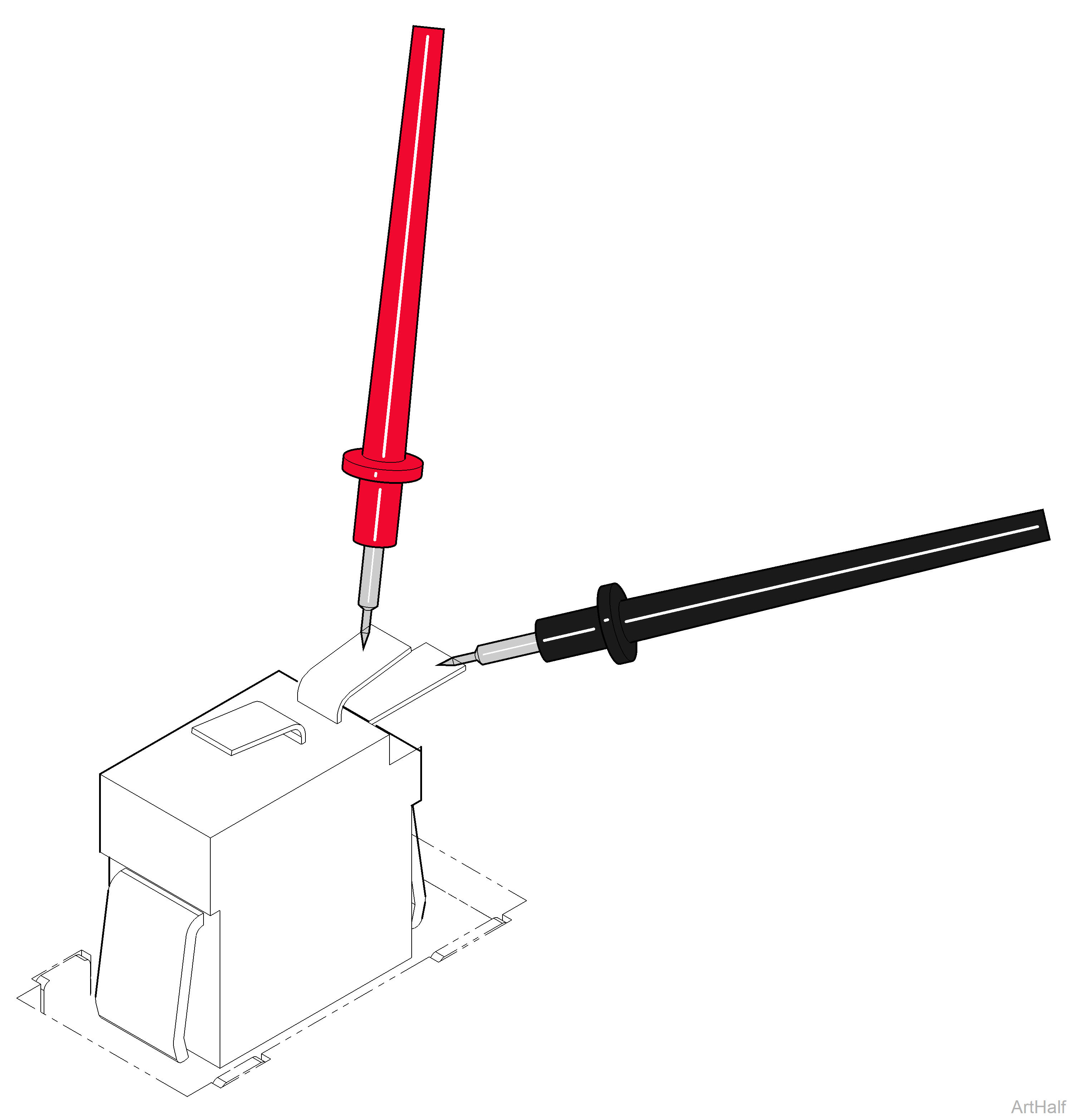
1.Tag and disconnect wires from switch.
2.Place meter probes on COM and NC terminals.
Check switch tripped and untripped.
| With Switch Tripped | |
|---|---|
|
Meter Reading |
Required Action |
|
OL |
Limit switch OK |
|
Less than 5 ohms |
Replace limit switch |
| With Switch Untripped | |
|---|---|
|
Meter Reading |
Required Action |
|
OL |
Replace limit switch |
|
Less than 5 ohms |
Limit switch OK Perform Actuator Motor Test |
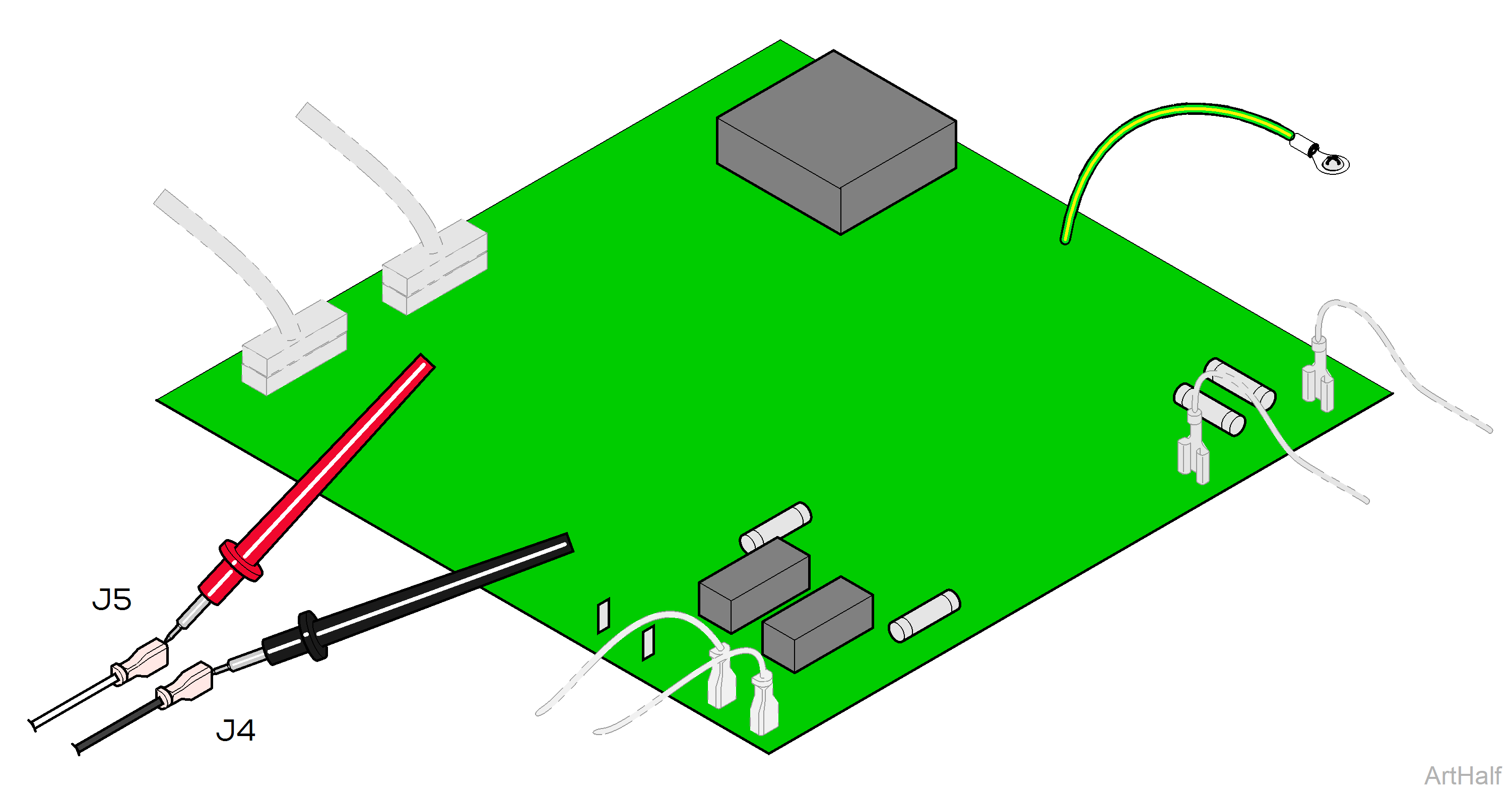
1.Tag and disconnect tilt actuator wires (J4 and J5).
2.Place meter probes on actuator wires. Check meter reading.
|
Meter Reading |
Required Action |
|---|---|
|
1 to 10 ohms |
Actuator motor OK Perform Motor Ground Test |
|
OL or less than 1 ohms |
Replace actuator motor.* |
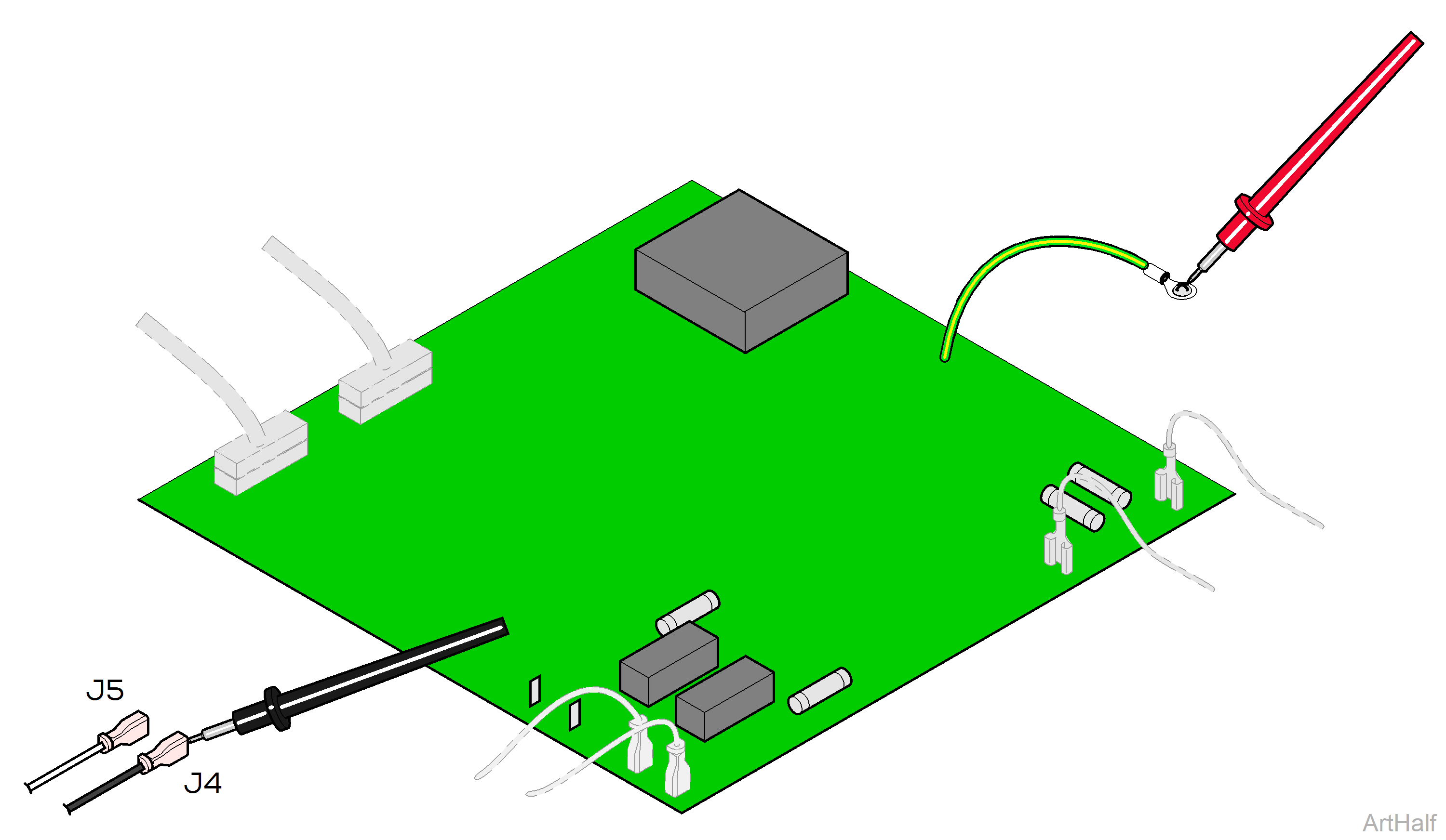
1.Place one meter probe on actuator wire (J4).
2.Place other meter probe on PC board ground wire.
3.Check meter reading. Repeat for J5.
|
Meter Reading |
Required Action |
|---|---|
|
OL or more than 1 mega-ohm |
Motor harness OK Perform PC Board Test |
|
Less than 1 ohm |
Replace actuator motor. |
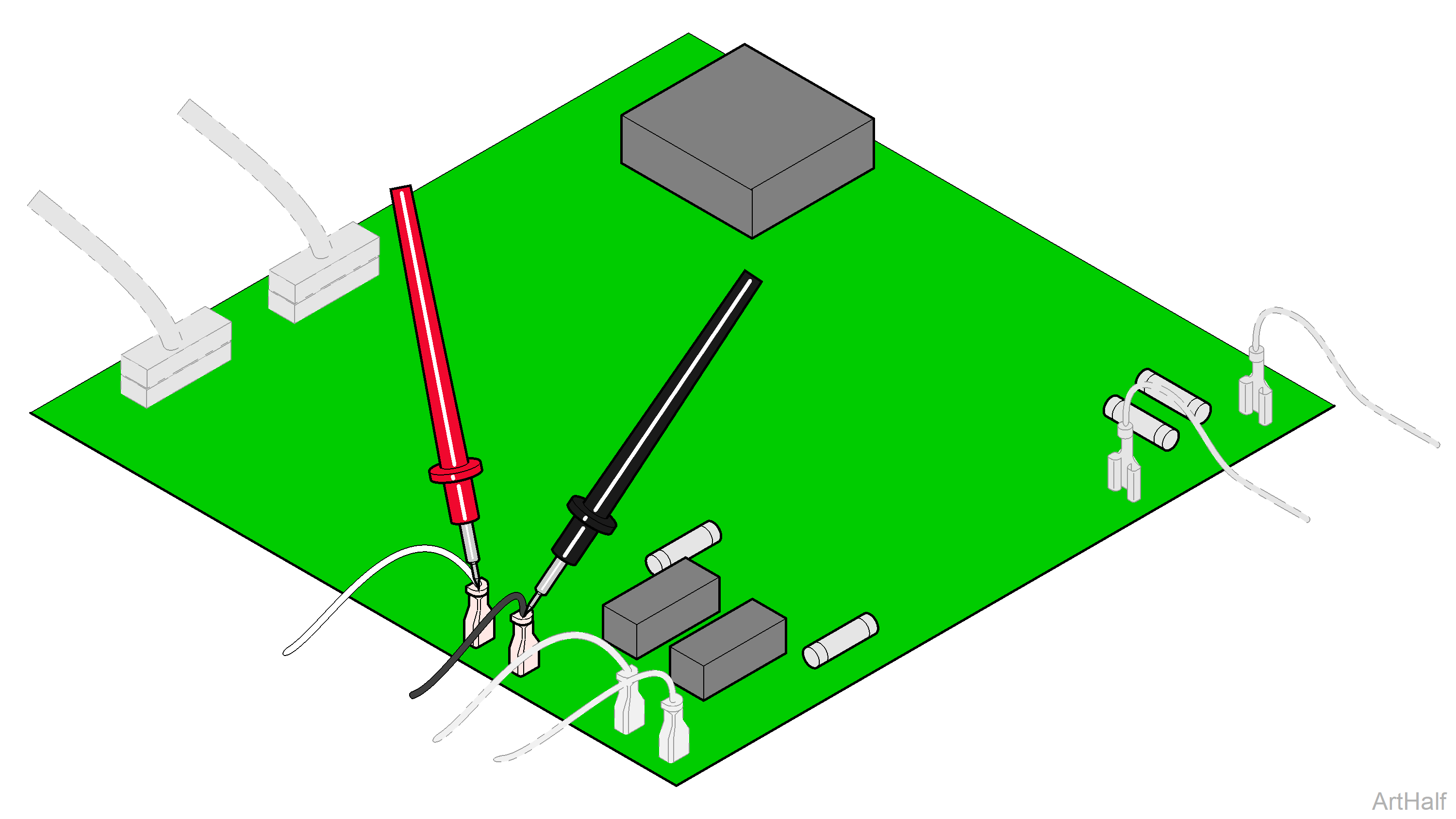
1.Place meter probes on wires at J4 and J5 terminals.
2.Check meter reading while activating Tilt Up / Tilt Down function with foot control.
|
Meter Reading |
Required Action |
|---|---|
|
Approximately 48 VDC |
PC board OK |
|
0 VDC |
Replace PC board |
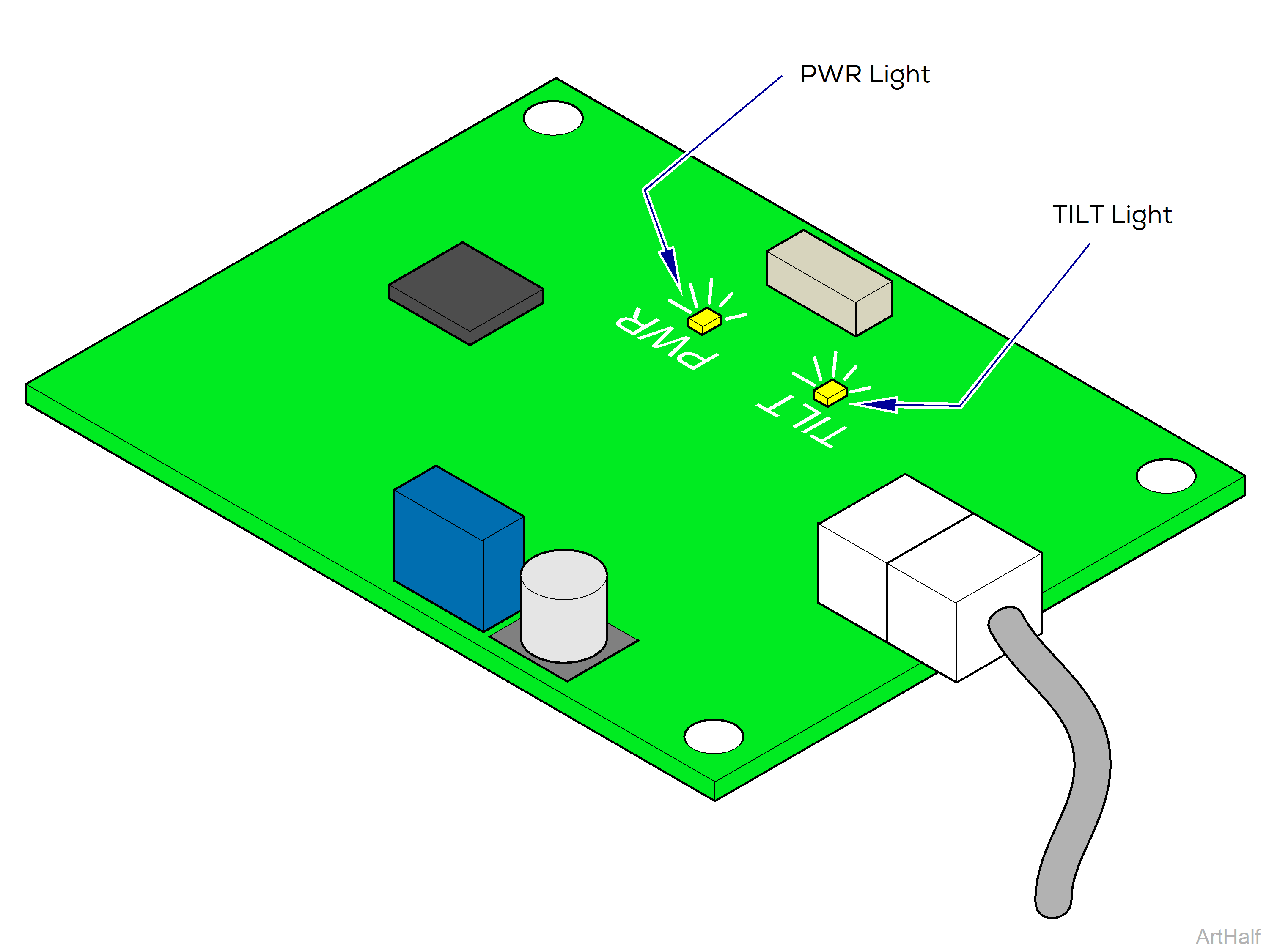
The sensor PC board functions like a normally closed, Tilt Up limit switch. When circuitry on the board detects that the tilt actuator has reached its upper limit, it interrupts current to the tilt actuator.
There are two indicator lights that can be used to determine proper operation of the sensor board. Replace board if Tilt light indicates a malfunction.
The PWR light is illuminated whenever voltage is supplied to the sensor board.
If this light is not illuminated, check all connections between the sensor board and the main PC board.
The TILT light indicates the status of the sensor board circuit.
If the light is On: Circuit is closed. Tilt Up function is operable.
If the light is Off: Circuit is open. Tilt Up function is inoperable.
This light should be On unless the Tilt function is in the full-up position.
There is only one limit switch for the Tilt function. The upper limit is controlled by the Sensor PC Board.
This illustration shows the tilt down limit switch, the sensor PC board, and the three serviceable components of the tilt actuator. Use the table below to isolate the malfunction.
|
Problem |
Required Action |
|---|---|
|
Tilt Up / Down OK, but beeps in full Up position. |
Perform Sensor PC board check |
|
Motor runs, but makes grinding noise. |
Clean / lube actuator threads. Replace actuator if necessary. |
|
Motor runs, but table does not move. |
Inspect / replace motor coupler. |
|
Motor does not run. |
Down only - Perform Limit Switch / PCB Harness Test |
There is only one limit switch for the Tilt function. The upper limit is controlled by the Sensor PC Board.
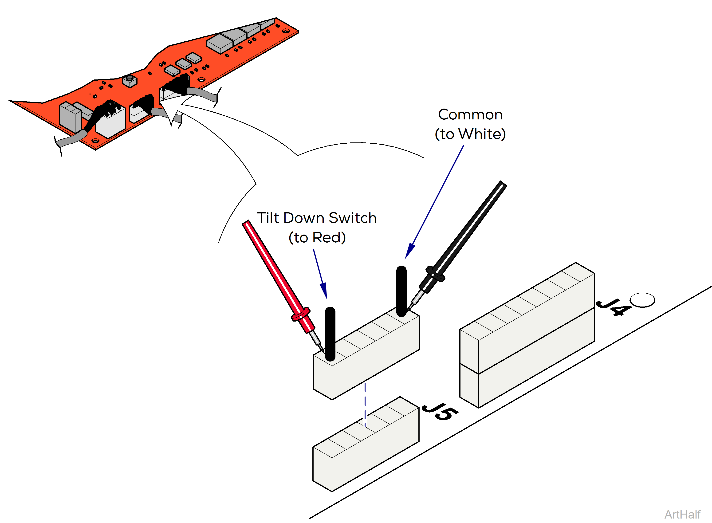
1.Disconnect harness from J5 on Motor Control PC board.
2.Place one meter probe on the common (white).
3.Place other probe on the Tilt Down Switch wire (see illustration).
Check switch tripped and untripped.
| With Tilt Down Switch Tripped | |
|---|---|
|
Meter Reading |
Required Action |
|
OL |
Limit switch / harness OK Perform Actuator Motor Test |
|
Less than 10 ohms |
Perform Limit Switch Harness Test |
| With Tilt Down Switch Untripped | |
|---|---|
|
Meter Reading |
Required Action |
|
OL |
Perform Limit Switch Harness Test |
|
Less than 10 ohms |
Limit switch / harness OK Perform Actuator Motor Test |
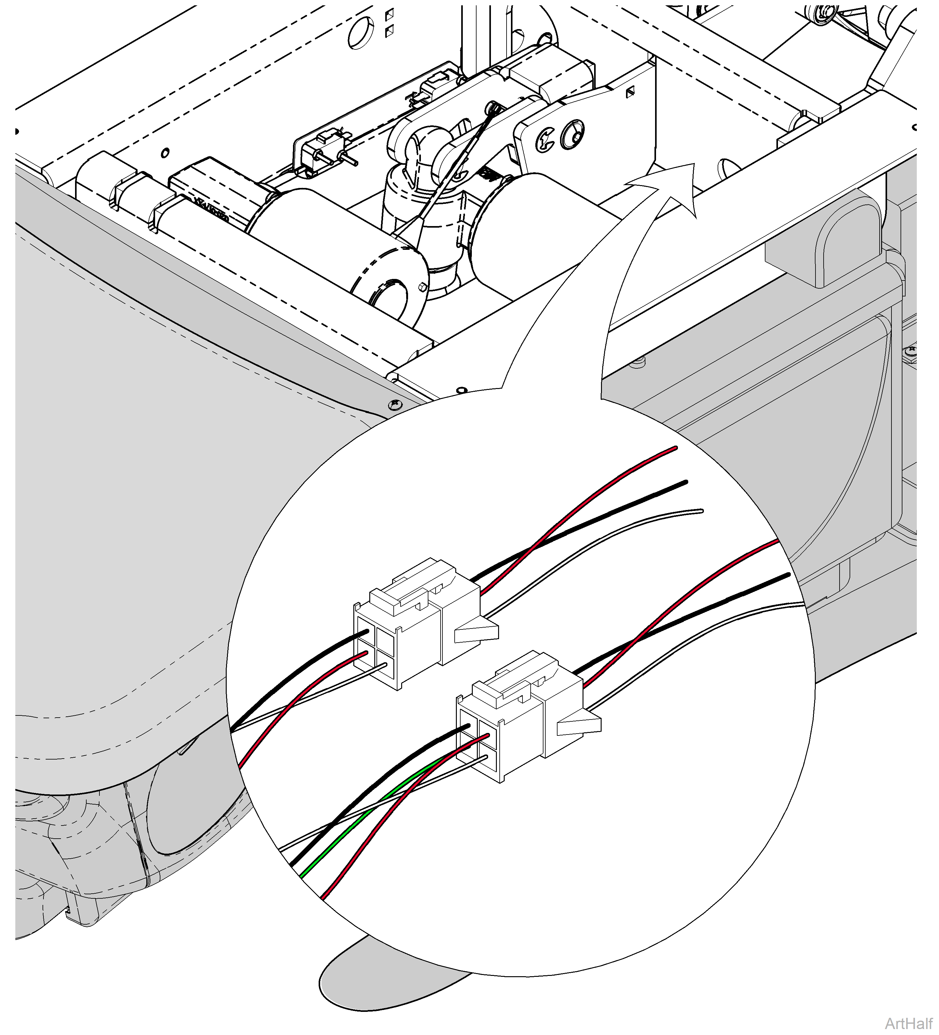
1.Unplug the appropriate limit switch harness.
2.Measure continuity.
|
Actuator Position |
Meter Reading Should Be |
|---|---|
|
Actuator Full Up |
White to Black - 3.3 VDC |
|
Actuator Full Down |
White to Black - 0 VDC |
|
Actuator Midway Point |
White to Black - 0 VDC |
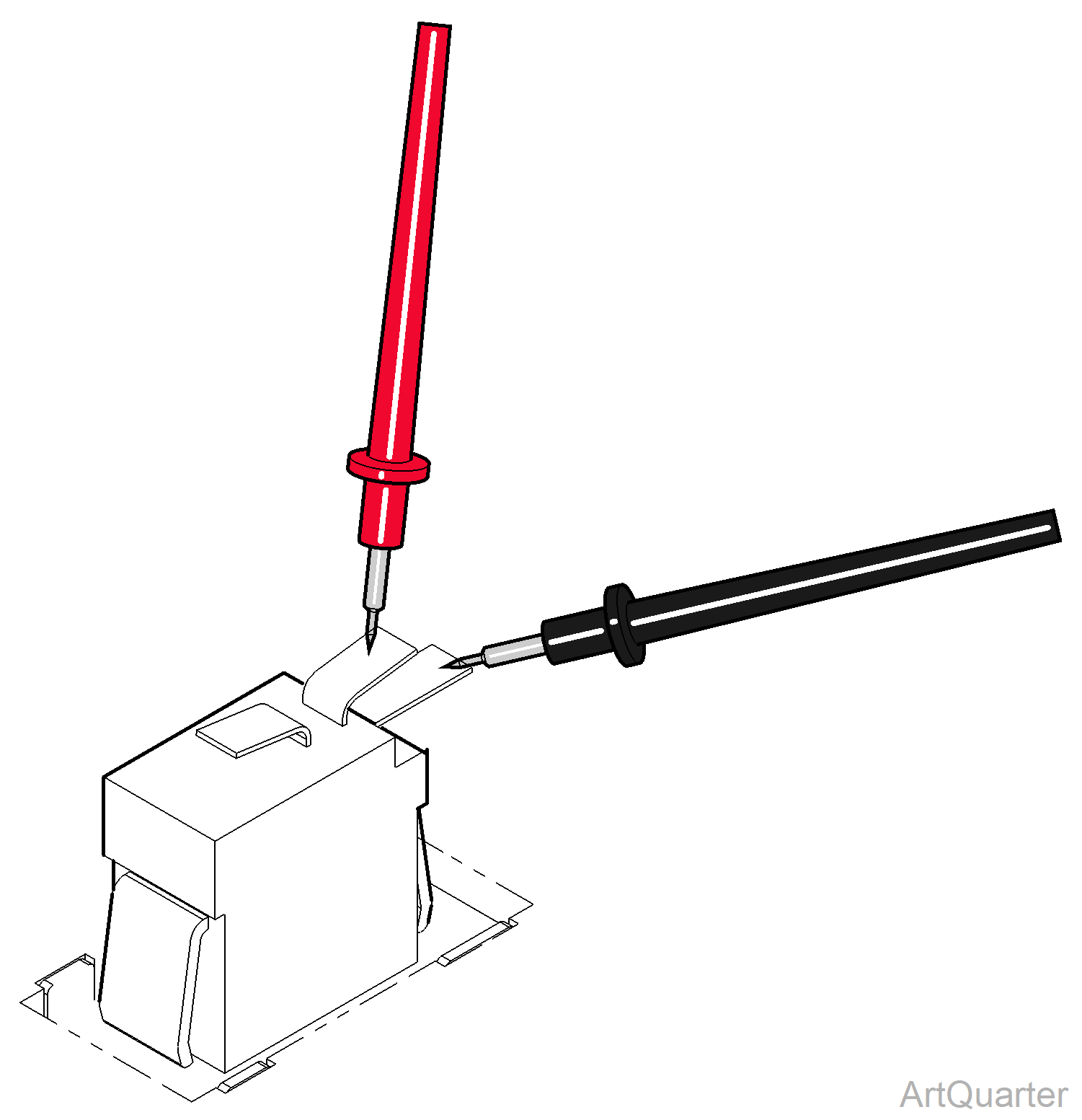
1.Tag and disconnect wires from switch.
2.Place meter probes on COM and NC terminals.
Check switch tripped and untripped.
| With Switch Tripped | |
|---|---|
|
Meter Reading |
Required Action |
|
OL |
Limit switch / harness OK |
|
Less than 5 ohms |
Replace limit switch |
| With Switch Untripped | |
|---|---|
|
Meter Reading |
Required Action |
|
OL |
Replace limit switch |
|
Less than 5 ohms |
Limit switch OK Perform Actuator Motor Test |
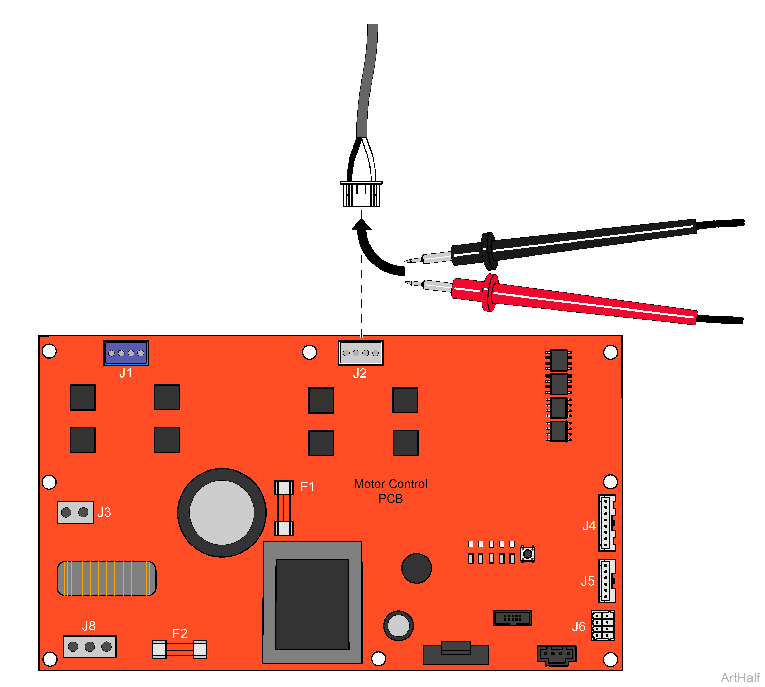
1.Disconnect power to the chair.
2.Disconnect Tilt actuator from J2 on PC Board.
3.Set multimeter to Ohms to check resistance.
4.Using a multimeter, place meter probes on actuator wires.
|
Meter Reading |
Required Action |
|---|---|
|
1 to 10 ohms |
Actuator motor OK Perform Motor Ground Test |
|
OL or less than 1 ohms |
Replace actuator motor |
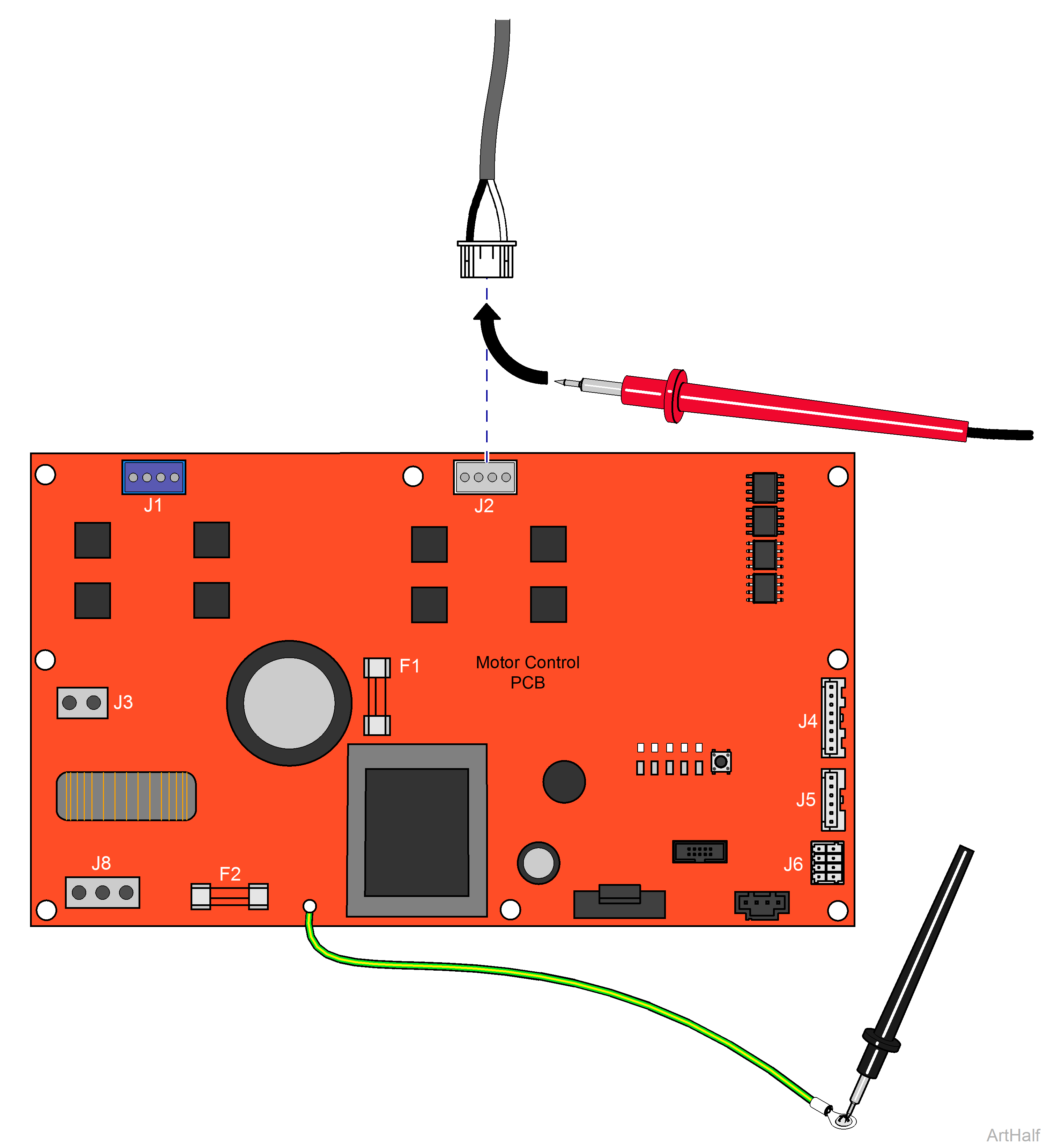
1.Place one meter probe on actuator Black wire (J2).
2.Place other meter probe on PC board ground wire.
3.Check meter reading.
4.Repeat steps for White wire.
|
Meter Reading |
Required Action |
|---|---|
|
OL or more than 1 mega-ohm |
Motor harness OK Perform PC Board Test |
|
Less than 1 ohm |
Replace actuator motor |
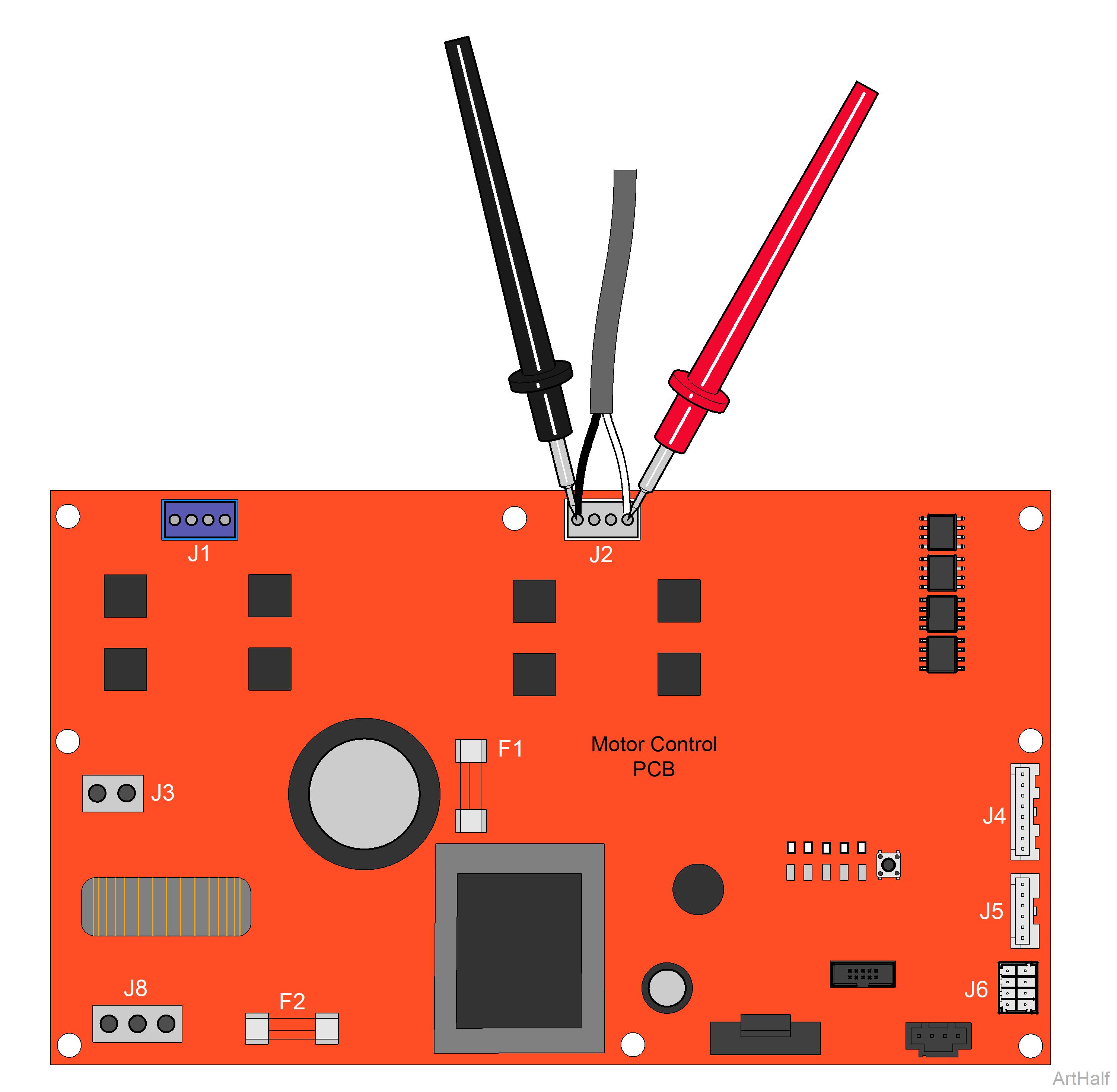
1.Place meter probes on Black and White wires at J2 on Motor Control PC board.
2.Check meter reading while activating Tilt Up / Tilt Down function with foot control.
|
Direction |
Meter Reading |
Required Action |
|---|---|---|
|
Tilt Up |
Approximately 48 VDC |
PC board OK |
|
Any Direction |
0 VDC |
Replace PC board |
|
Tilt Down |
Approximately 16 VDC |
PC board OK |
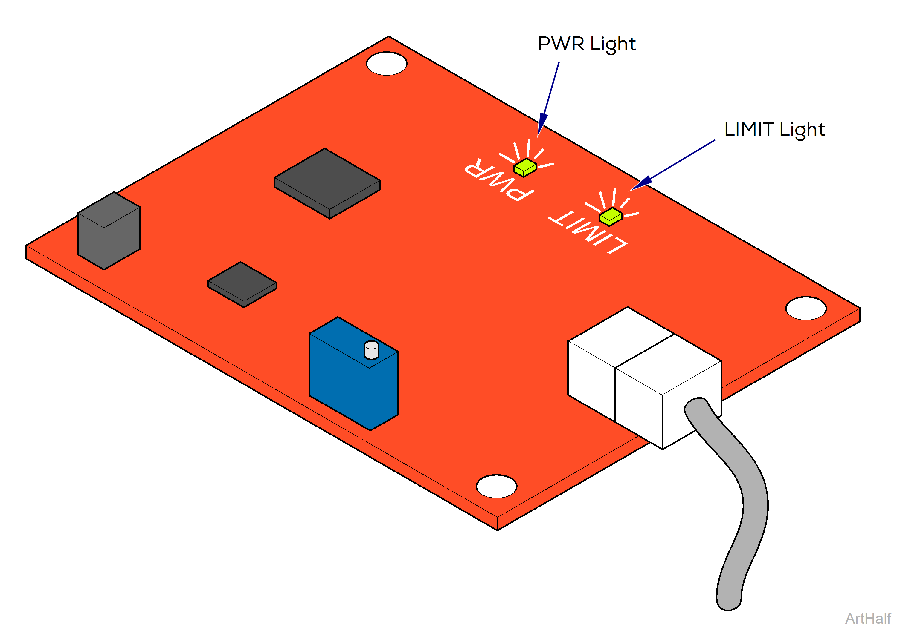
The Sensor PC board functions like a normally closed, Tilt UP limit switch. When circuitry on the board detects that the tilt actuator has reached its upper limit, it interrupts current to the tilt actuator.
There are two indicator lights that can be used to determine proper operation of the Sensor PC board. Replace PC board if Limit light indicates a malfunction.
The PWR light is illuminated whenever voltage is supplied to the Sensor PC board.
If this light is not illuminated, check all connections between the Sensor PC board and the Motor Control PC board.
The LIMIT light indicates the status of the Sensor PC board circuit.
If the light is On: Circuit is closed. Tilt Up function is operable.
If the light is Off: Circuit is open. Tilt Up function is inoperable.
This light should be On unless the Tilt function is in the full-up position.

