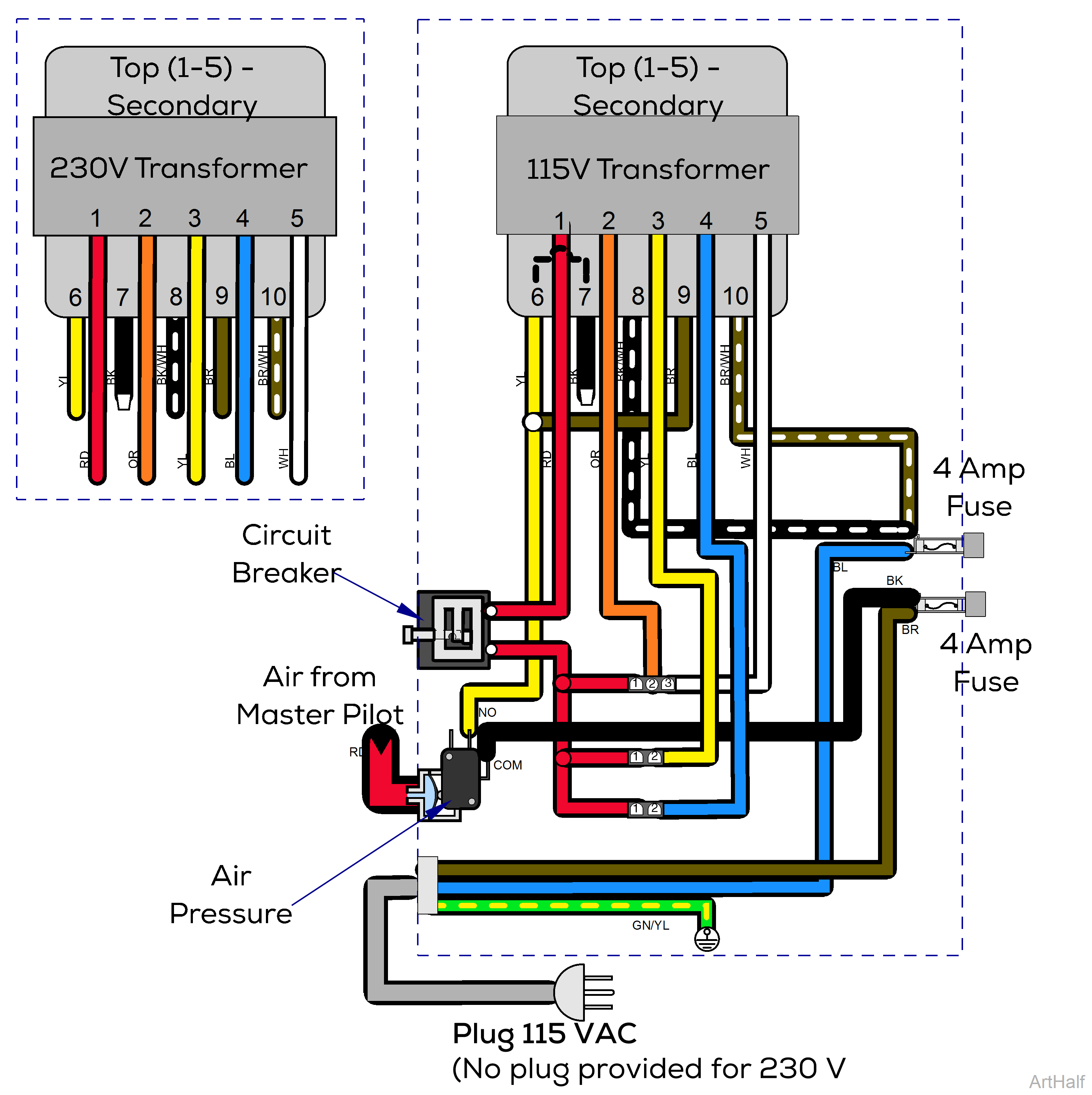
Power Supply 153606 and 153642 Wiring Diagram
Required Testing Conditions:
•Air Pressure Switch must be operated. Contacts COM and NO connected to BK and YL wires respectively.
•All fuses must be good.
•Circuit Breaker must be closed - button is extended, press to reset.
| Secondary Voltages (115 and 230 V) under NO Load |
||
|---|---|---|
|
Wire Colors |
Terminals |
Voltage |
|
RD - OR |
1 and 2 | 13.5 V |
| RD - YL | 1 and 3 | 15.0 V |
| RD - BL | 1 and 4 | 19.5 V |
| RD - WH | 1 and 5 | 25.0 V |
|
Voltage Check Test Points |
|
|---|---|
|
Voltage Reading |
Test Points |
| Line voltage at fuses | BL to BR wires at fuse holder |
| Line voltage to transformer | BK to BK/WT wires at fuse holders |
| BK to BR/WT wires at fuse holders | |
| YL wire at Air Switch to BK/WT at fuse holder | |
| YL wire at Air Switch to BR/WT at fuse holder | |
| 25.0 VAC supply to unit | Terminals 1 to 3 at Delivery Unit connector (RD to WH) |
| 13.5 VAC supply to unit | Terminals 1 to 2 at Delivery Unit connector (RD to OR) |
| 15.0 VAC supply to unit | Terminals 1 to 2 at Curing Light connector (RD to YL) |
| 19.5 VAC supply to light | Terminals 1 to 2 at Light connector (RD to BL) |
|
Continuity Check: Thermal Overload (O/L) |
Terminals 6 and 7 on the transformer should have transformer should have continuity (YL to BK) |
