222 Exam Table, 223 and 623 Table Foot / Hand Control Test and Repair
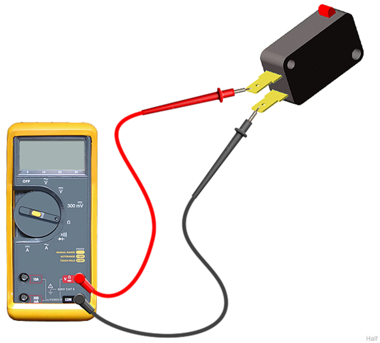
1.Remove foot control switch.
2.Set meter to 200 Ω.
3.Place meter probes on COM and NC terminals.
Check switch tripped and untripped.
| With Switch Untripped | ||
|---|---|---|
| Meter Reading | Status | Required Action |
|
Any resistance reading |
|
Replace switch |
|
OL |
|
Switch is good. Perform next check. |
| With Switch Tripped | ||
|---|---|---|
| Meter Reading | Status | Required Action |
|
Less than or = to 5 ohms |
|
Switch is good. Perform next check. |
|
OL |
|
Replace switch |
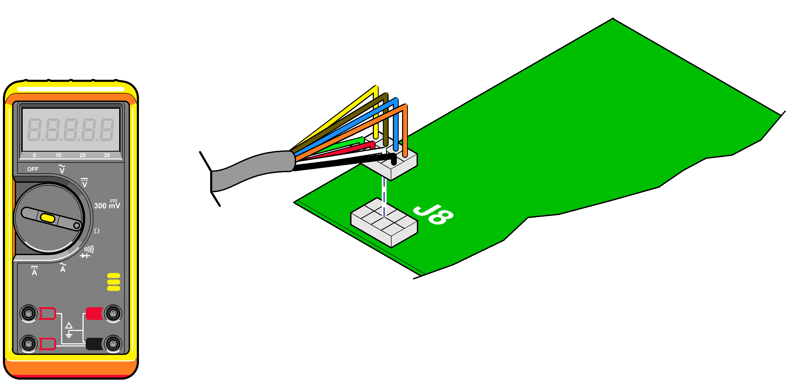
1.Disconnect wire harness from J8* on main PC board.
2.Set meter to 200 Ω.
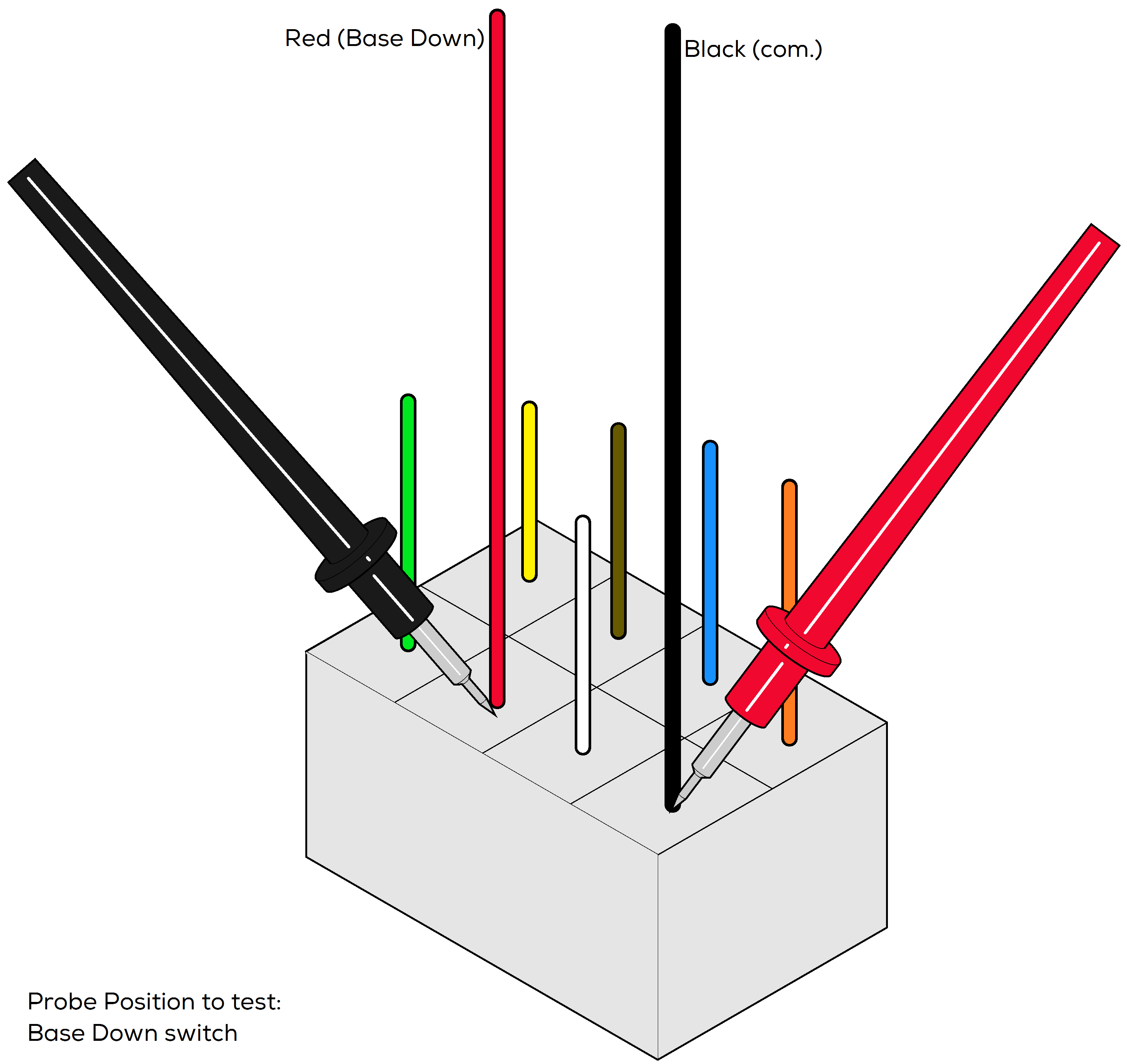
3.Place one meter probe on black wire (common)of foot / hand control harness. Place other meter probe on the wire that corresponds to the switch to be tested:
| Switch | Wire Color |
|---|---|
|
Base Up |
White |
|
Base Down |
Red |
|
Back Up |
Green |
|
Back Down |
Orange |
|
Auto Return |
Blue |
|
Stop |
Brown |
| With Switch Untripped | ||
|---|---|---|
| Meter Reading | Status | Required Action |
|
Any resistance reading |
|
Replace switch/switch membrane |
|
OL |
|
Switch is good. Perform next check. |
| With Switch Tripped | ||
|---|---|---|
| Meter Reading | Status | Required Action |
|
Less than or = to 5 ohms |
|
Switch is good. Perform next check. |
|
OL |
|
Replace switch/switch membrane |
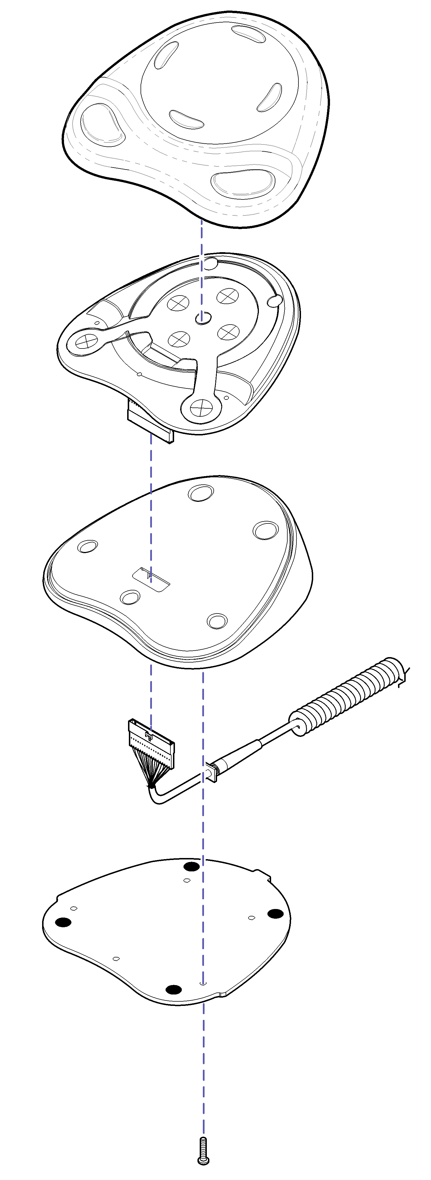
Removal
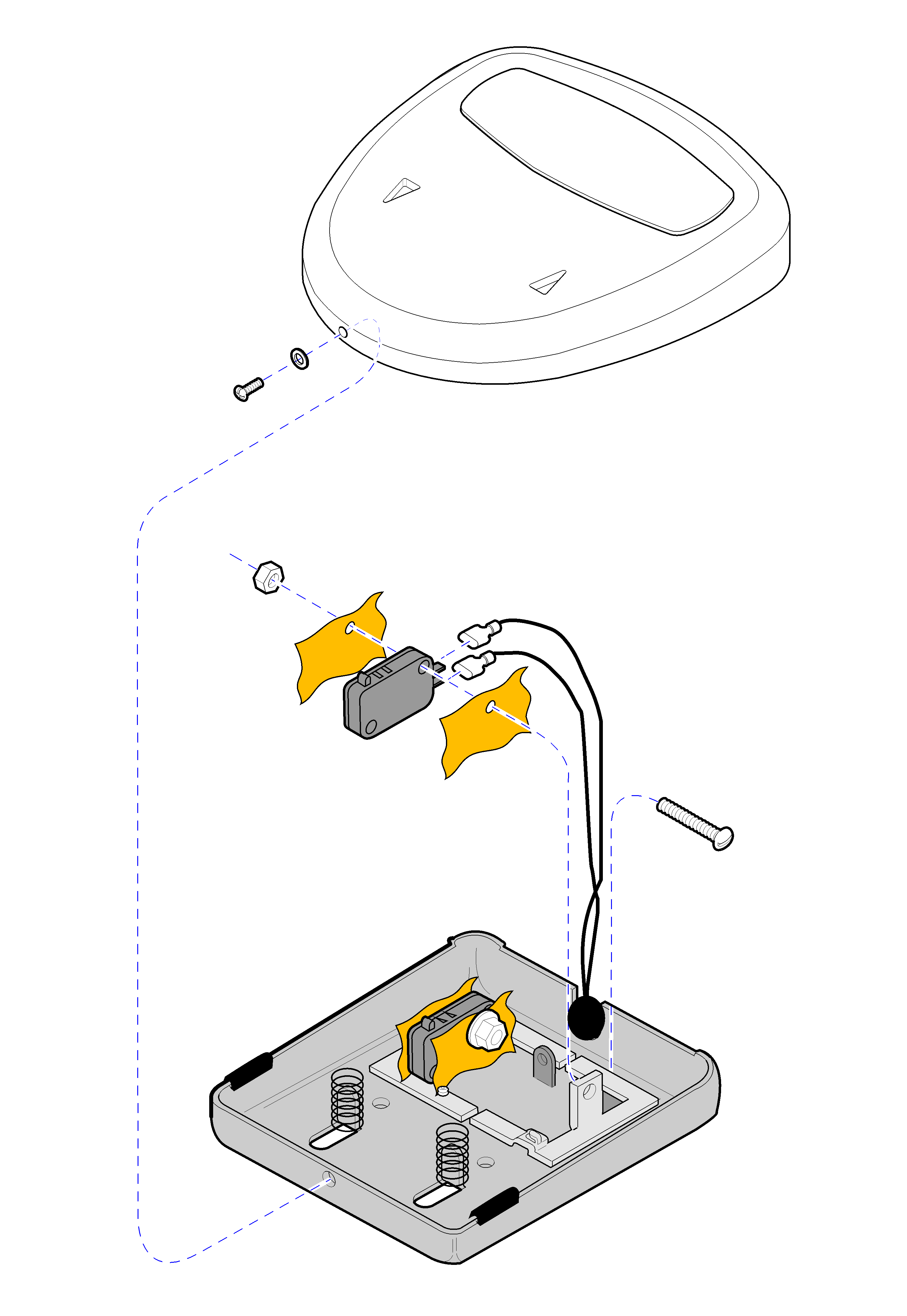
1.Remove Cover
2.Remove Switch. Disconnect wires.
Installation
1.Install switch. Connect wires.
2.Install cover.
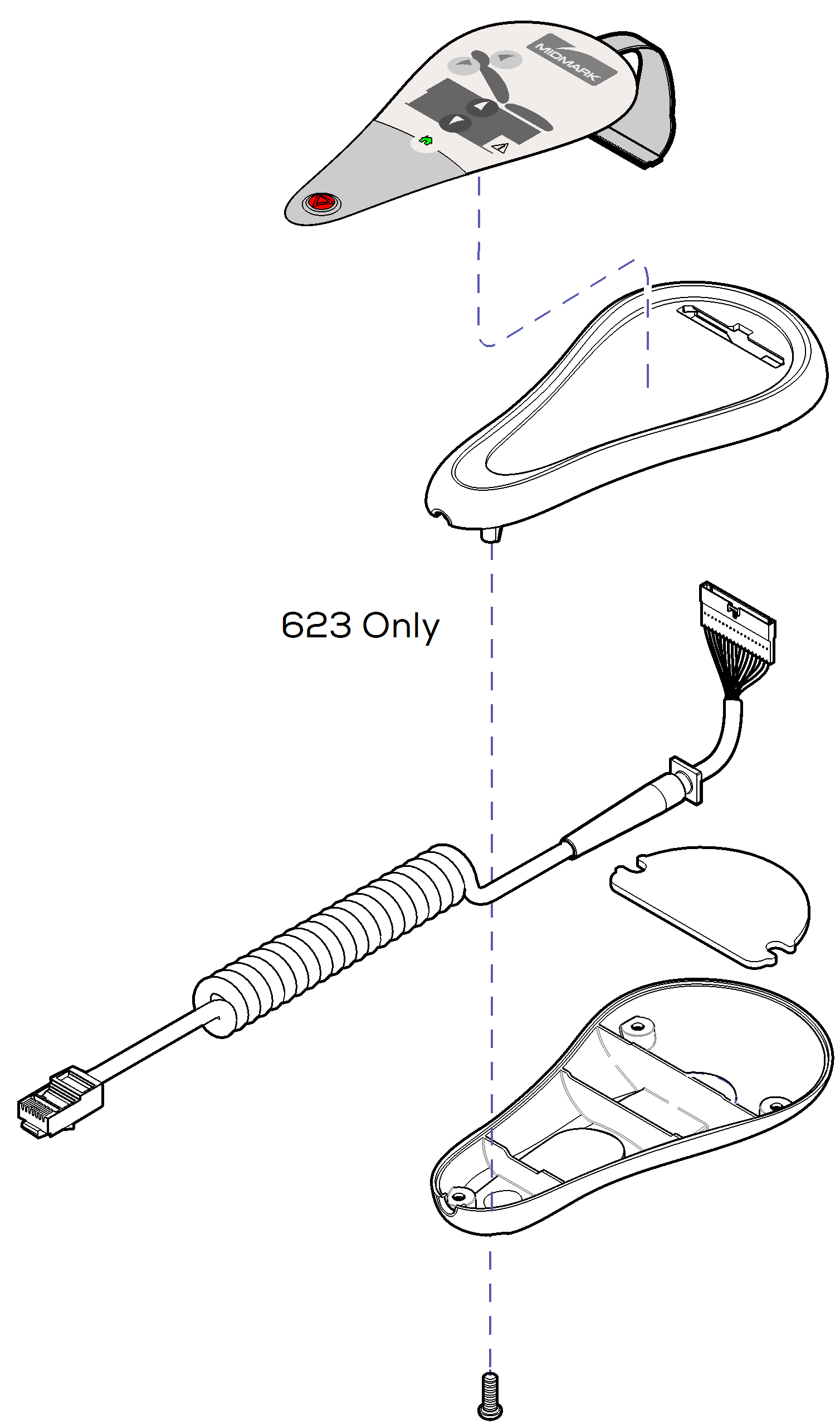
Installation
1.Install touch pad onto switch panel.
2.Insert control cord thru hole in base. Connect to membrane connector. Slide strain relief block (on cord) into slot on base.
3.Install base plate.
Removal
1.Remove base plate.
2.Disconnect control cord from membrane connector.
3.Peel touch pad off of switch panel.
