222 Exam Table, 223 and 623 Table Main PC Board Test and Repair
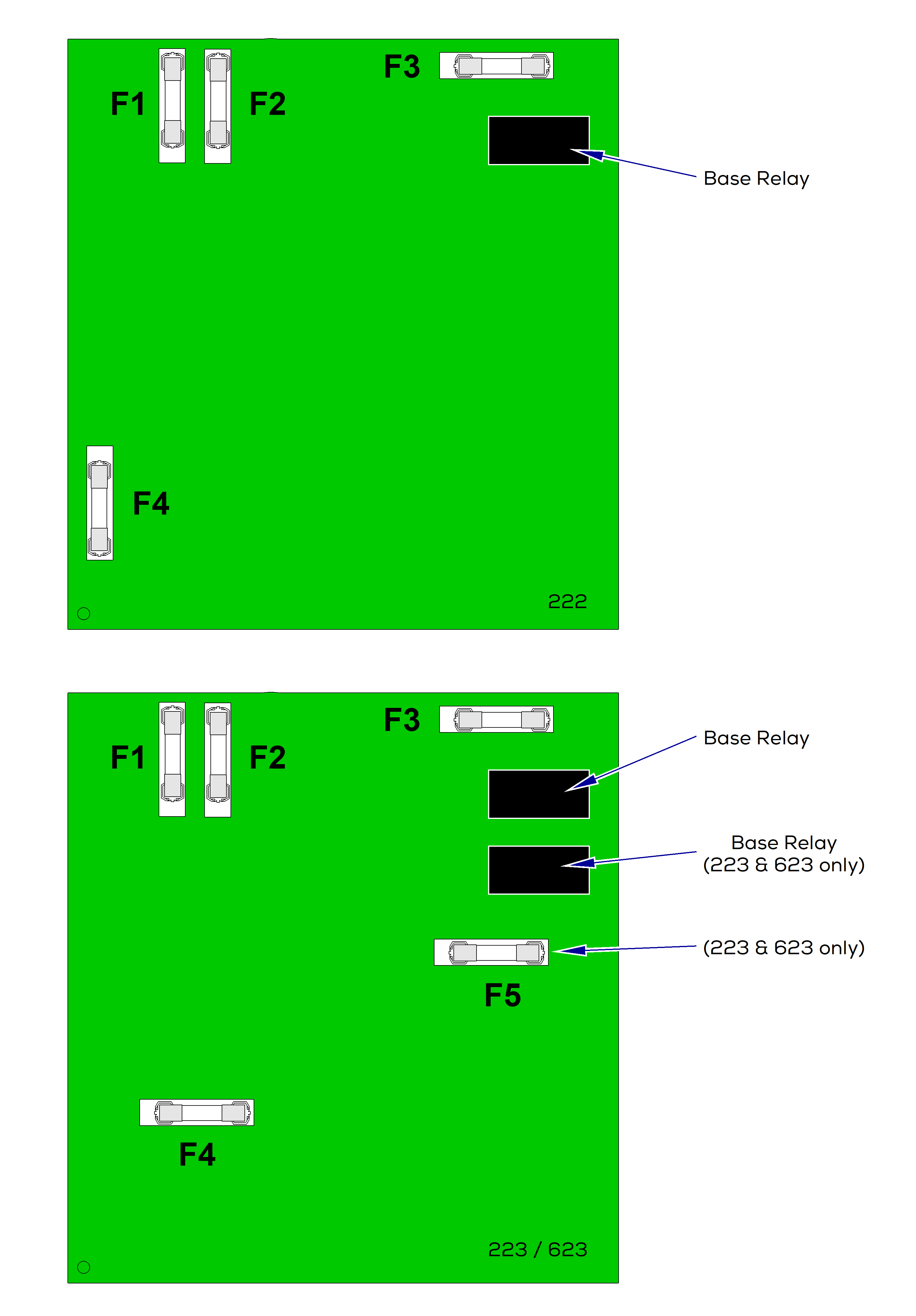
This illustration shows the location of the fuses on the Main PC Board. Use the table below to determine the required action.
| Problem | Required Action |
|---|---|
|
Base actuator motor does not run. |
Check fuses F1and F2, F3, F4. Perform Base Relay Test |
|
Back actuator motor does not run. |
Check fuses F1and F2, F3, F5. Perform Back Relay Test |
| 222 | |
|---|---|
| Single function / One Relay Fuses - Base Relay | |
|
F1 and F2 |
Primary Fuses - affect all functions |
|
F3 |
Base Motor Fuse - affects Base Up / Down |
|
F4 |
Transformer Fuse - affects all functions |
| 223 / 623 | |
|---|---|
| Dual function / Two relay Fuses - Base Relay and Back Relay | |
|
F1 and F2 |
Primary Fuses - affect all functions |
|
F3 |
Base Motor Fuse - affects Base Up / Down |
|
F4 |
Transformer Fuse - affects all functions |
|
F5 |
Back Motor Fuse - affects Back Up / Down |
Main PC Board Base / Back Relay test
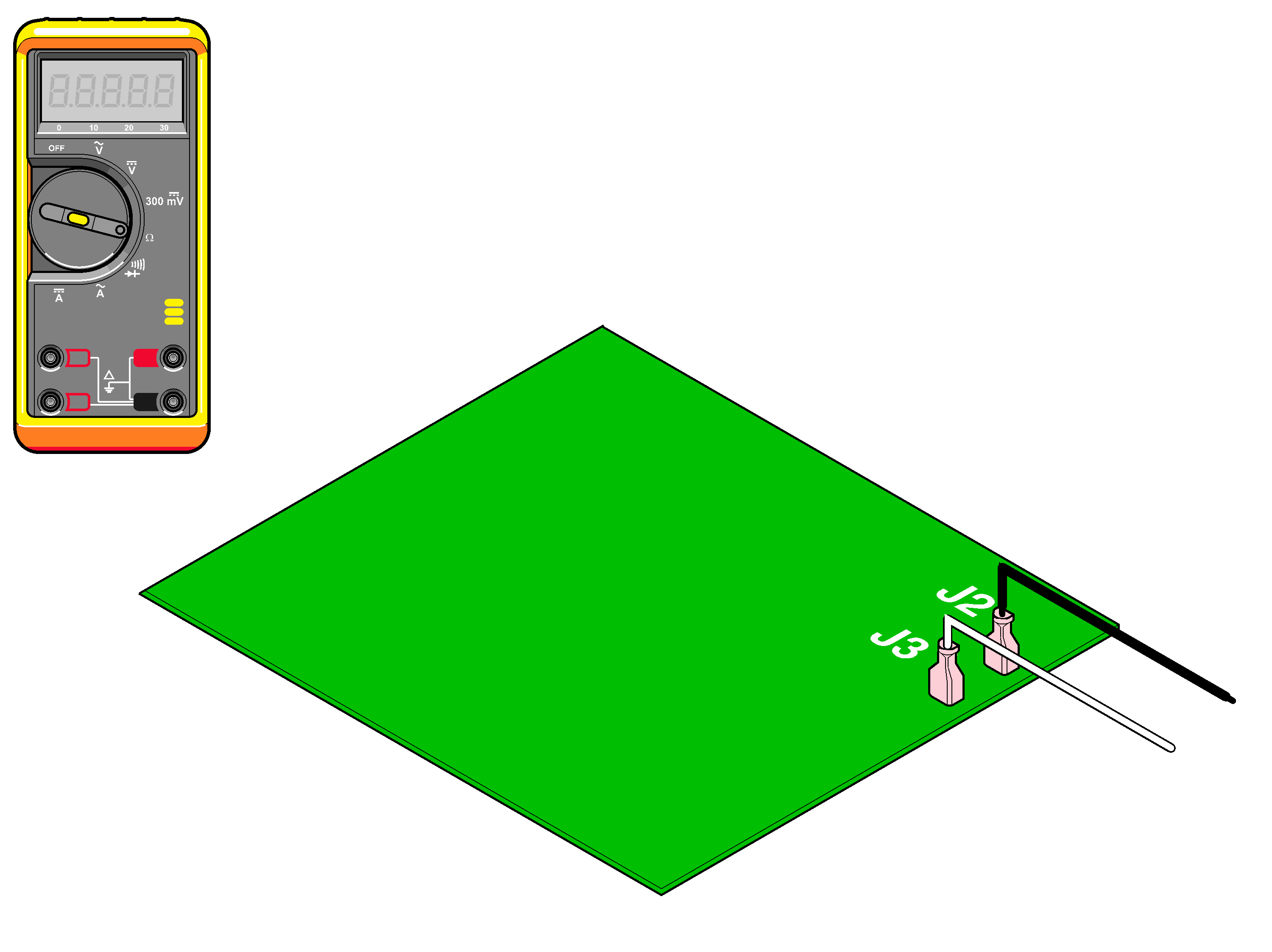
1.Set meter to VDC.
2.Clip meter test hooks terminals at J2 and J3.
3.Activate Base Up / Down function using the foot or hand control.
| Meter Reading | Status | Required Action |
|---|---|---|
|
Approximately 48 VDC |
|
PC Board is good. Perform next check. |
|
0 VDC |
|
Replace PC Board. |
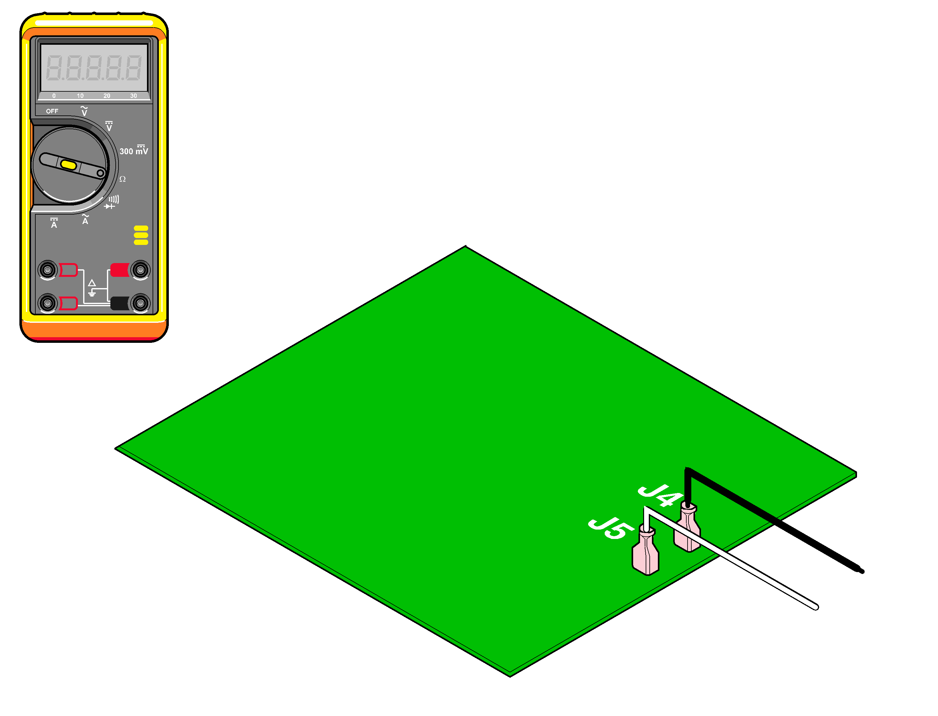
1.Set meter to VDC.
2.Clip meter test hooks terminals at J4 and J5.
3.Activate Back Up / Down function using the foot or hand control.
| Meter Reading | Status | Required Action |
|---|---|---|
|
Approximately 48 VDC |
|
PC Board is good. Perform next check. |
|
0VDC |
|
Replace PC Board. |
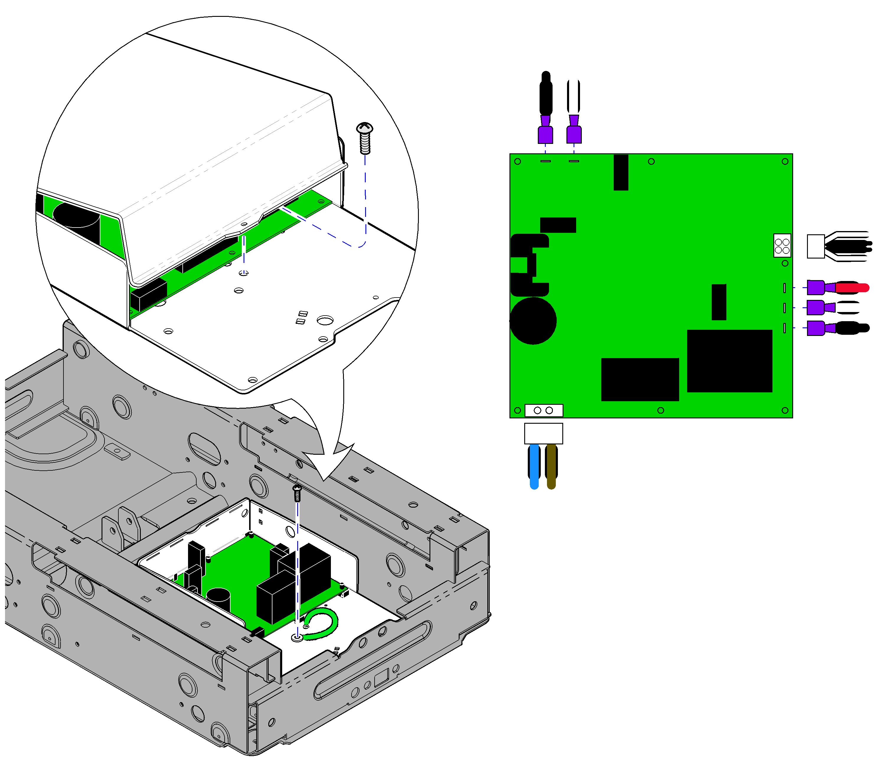
1.Remove outer shrouds. Refer to:Table Shroud Removal
Unplug power cord before removing PC Board cover.
2.Unplug power cord and remove PC Board cover.
3.Disconnect ground wire. Tag and disconnect wiring from PC Board.
4.Remove PC Board.
1.Install PC Board.
2.Connect ground wire. Connect all wiring.
3.Replace PC Board cover.
4.Replace outer shrouds. Refer to:Table Shroud Removal

