PowerVac G PC Board and Daughter Card Test and Repair
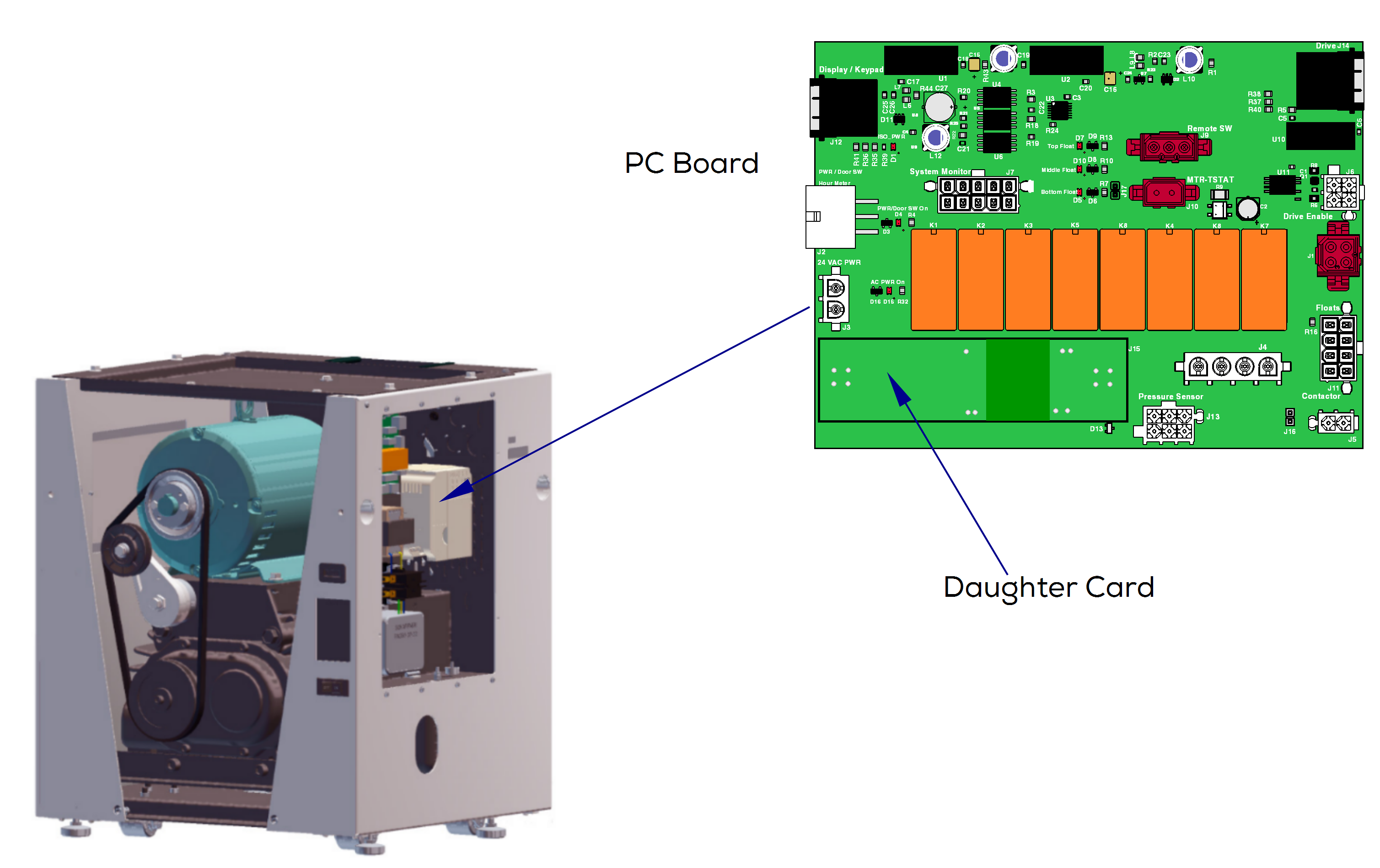
The PC Board is located in the electrical box and performs a number of various functions. These include: isolating circuits, main control for the unit, and provides a 24 Volt DC power supply to power the pressure sensor. There are no fuses or other serviceable parts on the PC Board, however there are six LED indicator lights for troubleshooting. The lights and connectors are all labeled on the board.
| LED Light | Label | Indicates |
|---|---|---|
| D5 | AC PWR ON | Indicates that the unit is getting power. |
| D4 | PWR / DOOR ON | Indicates the door limit switch, the power switch, and the Master Control switch is closed. Does this when the front cover is on. |
| D1 | ISO PWR | Indicates that 5 Volts DC provided by the drive is present at the keypad. |
| D5 | Bottom Float | Indicates the bottom float switch is closed. |
| D10 | Middle Float | Indicates the middle float switch is closed. |
| D7 | Top Float | Indicates the top float switch is closed. |
When testing components with power on, use care to prevent electrical shock.
When working on Twin units, unplug parallel harness.
1.Turn power off at on/off switch and main power supply box. The separator tank should have drained when unit was turned off. Verify it is not full.
2.Remove electrical cover. Refer to: Electrical Cover
3.Make sure the front cover is installed and the safety switch is engaged.
4.Turn main power supply and on/off switch on.
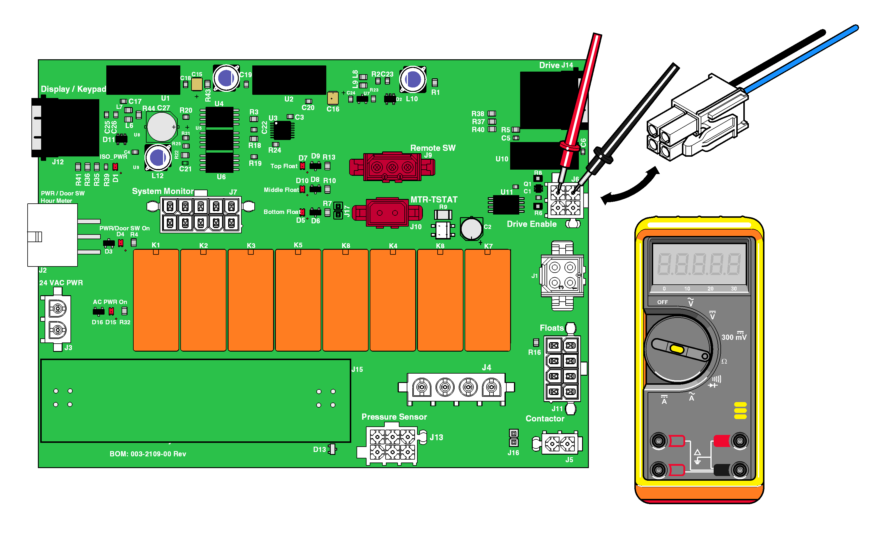
5.With the vacuum running, unplug wire harness from J6 on PC board. Set meter to Ω. Test resistance at J6 as shown.
Ensure the cable going to J14 is connected securely to avoid a false reading.
|
Meter Reading |
Required Action |
|---|---|
|
< 5 ohms |
PC Board Ok |
|
> 5 ohms |
Replace PC Board |
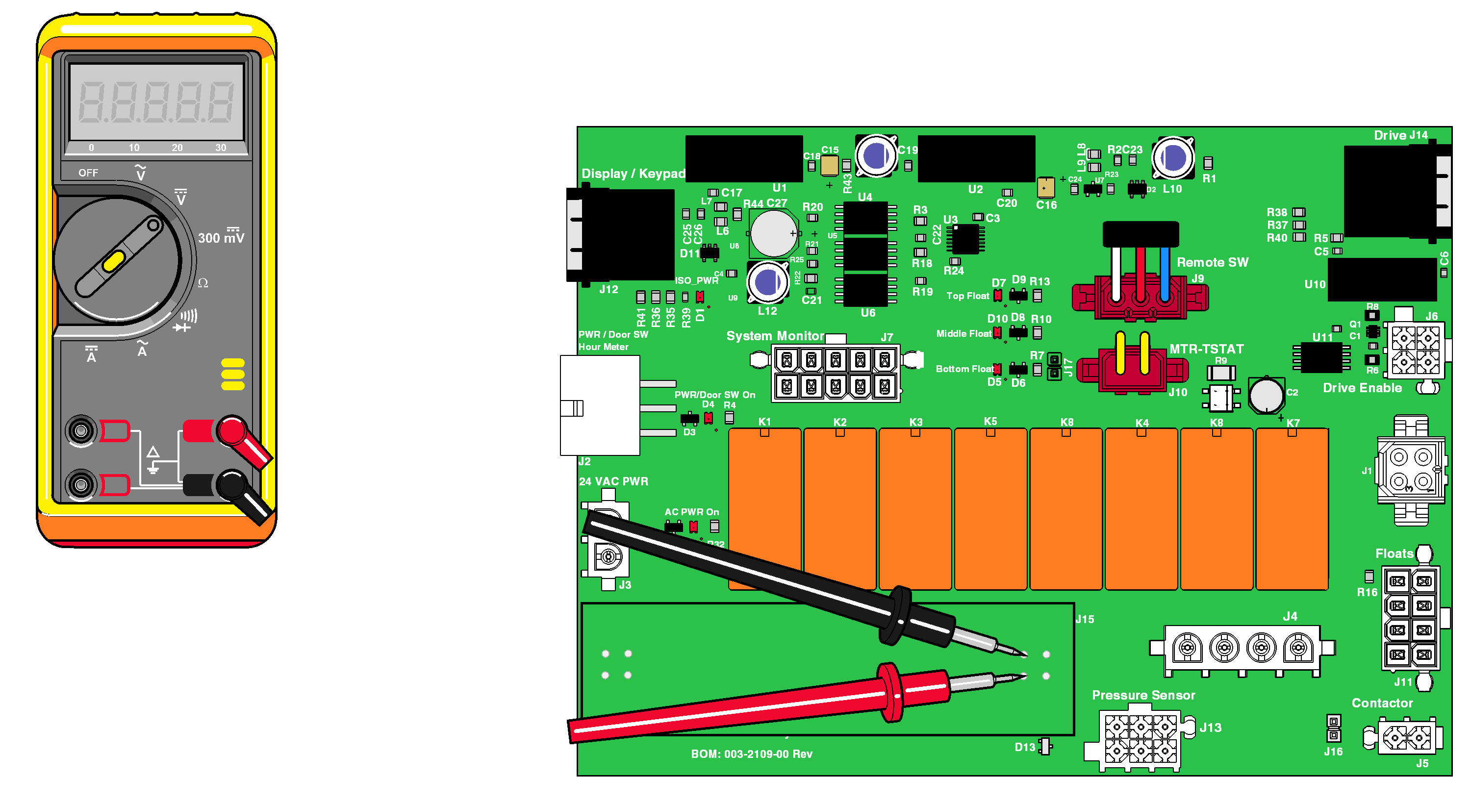
1.Set meter to VDC. Place probes at J2 Daughter Card connection as shown.
|
Meter Reading |
Required Action |
|---|---|
|
< 24 VDC |
Replace Daughter Card |
|
24 VDC -2 / +4 |
Daughter Card OK |
